Electric lines of the future
In 2003, a large Desertec project emerged in the European Union, representing the then vision of switching Europe to renewable energy. The basis of the “green energy” of the EU was to become thermal power plants with a concentration of solar energy, located in the Sahara desert, capable of storing energy for at least the evening peak of consumption, when conventional photovoltaics no longer work. A feature of the project should have been the most powerful power lines (LEP) for dozens of gigawatts, with a range from 2 to 5 thousand km.
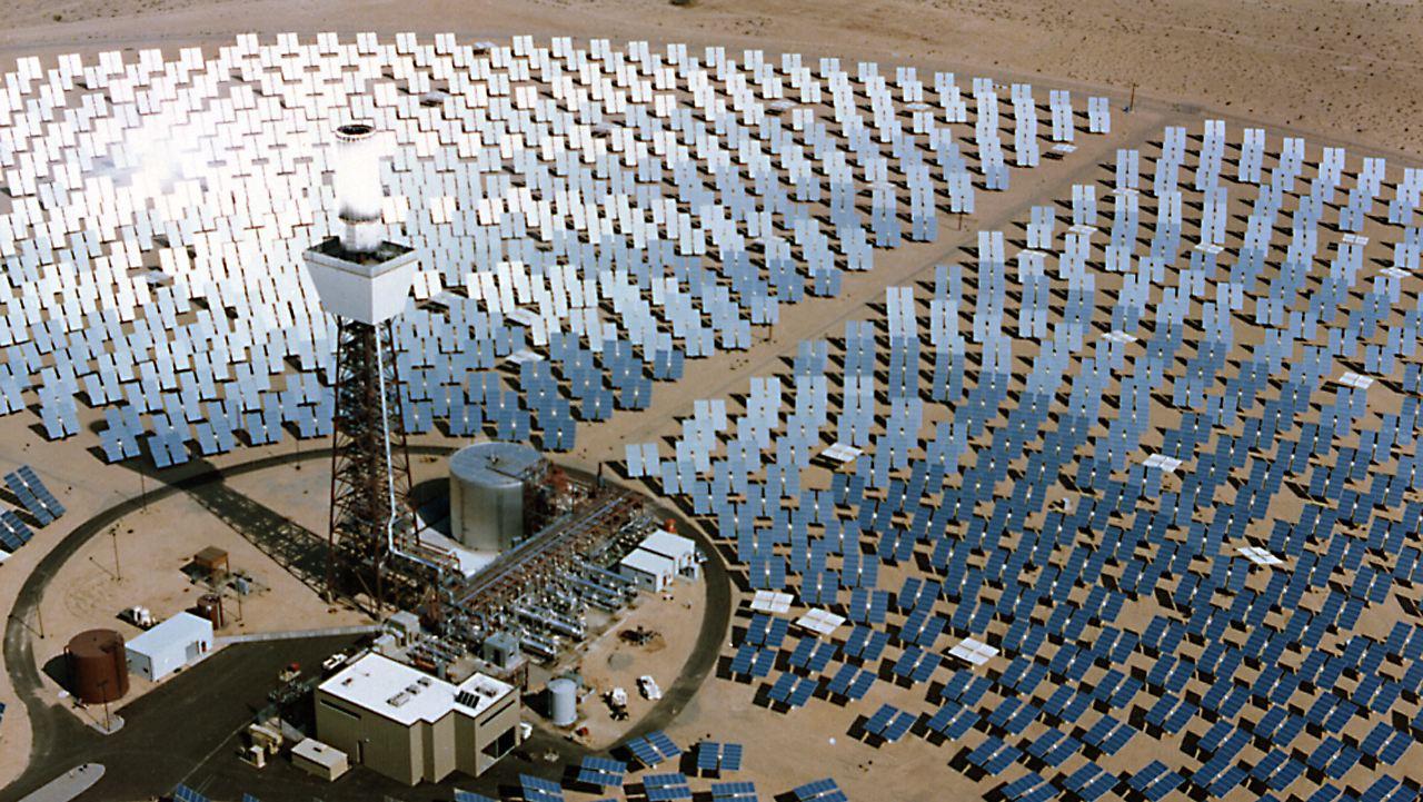
SES of this kind were to become the main European renewable energy.
The project existed for about 10 years, and then was abandoned by the founding concerns, since the reality of European green energy turned out to be completely different and more prosaic - Chinese photovoltaics and ground-based wind generation in Europe itself, and the idea of drawing energy lines through Libya and Syria is too optimistic .
')
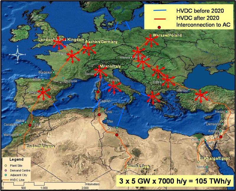
Planned as part of desertec power lines: three main areas with a capacity of 3x10 gigawatts (in the picture one of the weaker versions with 3x5) and several submarine cables.
However, powerful power lines appeared in the desertec project not accidentally (funny, by the way, the land area under power lines in the project produced more land under SES) - this is one of the key technologies that can allow RES generation to grow to an overwhelming proportion, and vice versa: in the absence of energy transfer technology over long distances, renewable energy sources may well be doomed to no more than a share of 30-40% in the European power industry.
Mutual synergy of transcontinental power lines and renewable energy is quite clearly visible on models (for example, in the giant LUT model , as well as in the Vyacheslav Laktushin model ): the unification of many wind-generation regions that are 1-2-3 thousand kilometers apart destroy each other. generation (dangerous total failures) and evens the amount of energy entering the system. The only question is, at what price and with what losses is it possible to transfer energy over such distances. The answer depends on different technologies, which today are essentially three: transmission by alternating current, direct current and superconducting wire. Although such a division is a bit wrong (a superconductor can be with alternating and direct current), but from a system point of view it is legitimate.

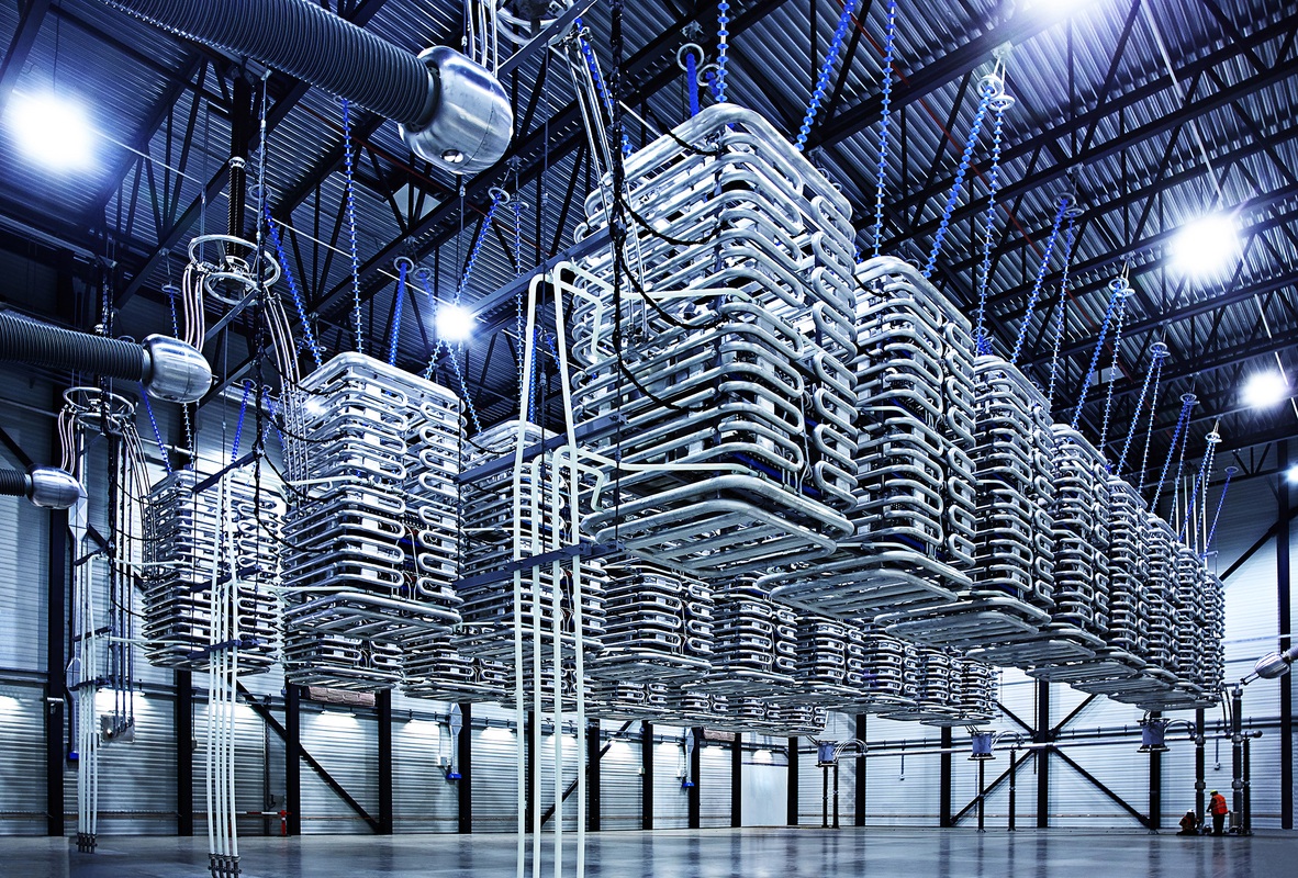
However, the technique for high voltage transmission, in my opinion, is one of the most fantastic looking. The photo shows a 600 kV rectifier station.
From the very beginning, traditional electric power industry followed the path of uniting electricity generation with the help of high-voltage alternating current power lines, having reached 750-800-kilovolt transmission lines in the 70s, capable of transmitting 2-3 gigawatts of power. Such power lines come to the limits of the capabilities of classic AC networks: on the one hand, system limitations related to the complexity of synchronization of networks thousands of kilometers long and the desire to divide them into power regions connected by relatively small insuring lines, and on the other hand, the increase in reactive power and the loss of such a line (due to the fact that the inductance of the line and capacitive coupling to the ground).
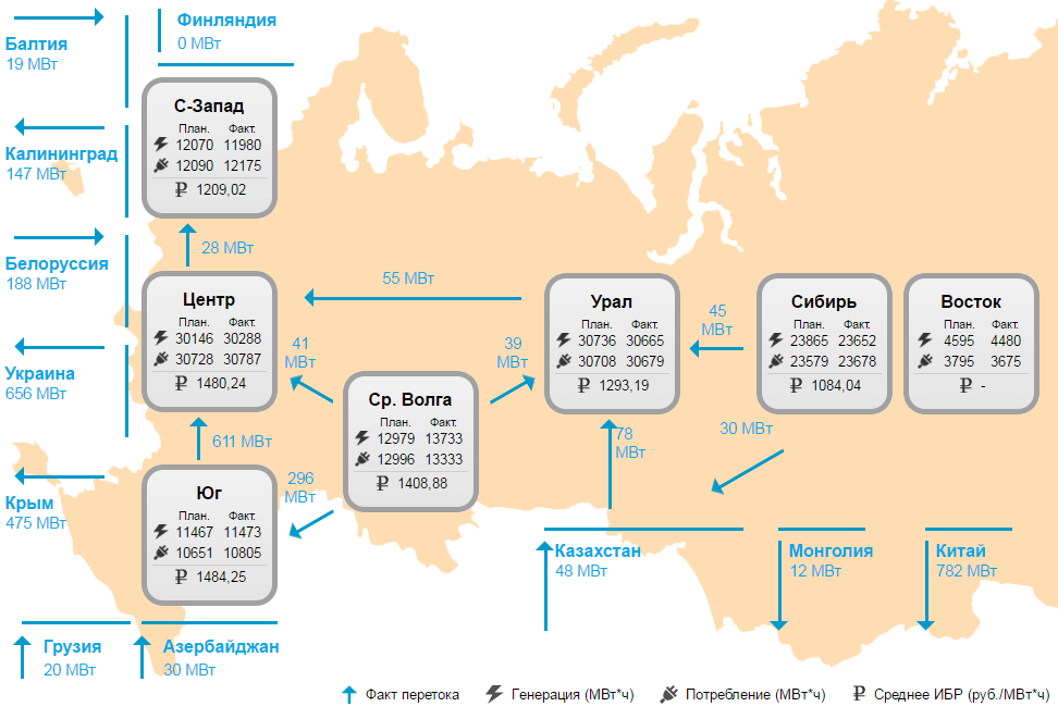
The picture is not quite typical in the power industry of Russia at the time of writing this article, but usually the flows between areas do not exceed 1-2 GW.
However, the appearance of the power systems of the 70s-80s did not require high-power and long-distance power lines - the power station was most often more convenient to push towards consumers, and the only exception was the renewable energy sources - hydrogeneration.
Hydroelectric power plants, and specifically the Brazilian Itaipu HPP project in the mid-80s, led to the emergence of a new champion in the transmission of electricity a lot and far away - direct current lines. The power of the Brazilian link is 2x 3150 MW at a voltage of +600 kV at a distance of 800 km, the project is implemented by ABB. Such capacities are still on the verge of available AC power lines, but the greater losses paid for the project with conversion to direct current.

Itaipu HPP with a capacity of 14 GW is still the second in the world in terms of HPP capacity. A portion of the energy produced is transmitted via the HVDC link to the area of San Paolo and Rio de Geineiro.
Unlike AC power lines, power lines PT are free from inductive and capacitive losses (i.e., losses through the parasitic capacitive and inductive connection of the conductor with the surrounding earth and water), and were actively used primarily by connecting submarine cables to the general grid of large islands where the loss of the AC line in the water could reach 50-60% of power. In addition, the PTL transmission lines with the same voltage level and wire cross section are capable of transmitting 15% more power through two wires than three AC transmission lines. The problems with insulation in power lines PT are simpler - in fact, at an alternating current, the maximum voltage amplitude is 1.41 times greater than the current, for which power is considered. Finally, PT PTL does not require synchronization of generators on two sides, and therefore eliminates many problems associated with synchronization of remote areas.

Comparison of AC (AC) and DC (DC) current. The comparison is a bit advertising, because with the same current (say, 4000 A), 800 kV AC power lines will have a power of 5.5 GW versus 6.4 GW of DC power lines, but with twice the losses. With equal losses, power will really be 2 times different.
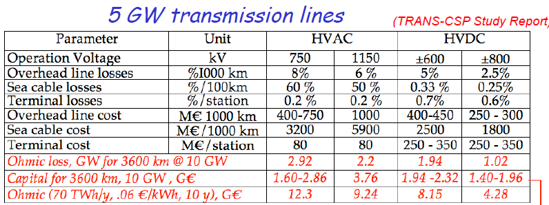
Calculation of losses for different power transmission lines, which were supposed to be used in the project Desertec.
Of course, there are downsides, and significant. First, the direct current in the AC power system requires rectification on the one hand and “twisting” (ie, generating a synchronous sine) on the other. When it comes to many gigawatts and hundreds of kilovolts - this is done by very nontrivial (and very beautiful!) Equipment, which costs many hundreds of millions of dollars. In addition, until the beginning of the 2010s, PTL PTs could only be of the “point-to-point” type, since there were no adequate switches for such DC voltages and powers, which means that with many consumers, it was impossible to cut off one of them with a short circuit - just pay off the whole system. This means that the main use of high-power transmission lines PT is the connection of two energy districts where large power flows were needed. Just a few years ago, ABB (one of the three leaders in the creation of HVDC equipment) managed to create a “hybrid” thyristor-mechanical switch (similar in ideas to the ITER switchboard) that is capable of such work, and the first high-voltage power transmission line PT multi-point "North-East Angra in India.
The ABB hybrid switch is not expressive enough (and not very illuminated), but there is a megaphos Hindu video on the assembly of a mechanical switch for a voltage of 1200 kV - an impressive machine!
Nevertheless, the PT-energy technology developed and became cheaper (largely due to the development of power semiconductors), and by the advent of gigawatts, RES-generation was quite ready to start connecting remote powerful hydroelectric power stations and wind farms to consumers. Especially many such projects have been implemented in recent years in China and India.
However, the thought goes further. In many models, PT-LEP power transmission capabilities are used to equalize renewable energy variability, which is a major factor in the implementation of 100% renewable energy sources in large power systems. Moreover, this approach is already being implemented in practice: you can give an example of a 1.4-gigawatt link Germany-Norway, designed to compensate for the variability of German wind generation by the Norwegian power stations and hydroelectric power stations and the 500 megawatt link Australia-Tasmania needed to maintain the power system of Tasmania (mainly working on hydroelectric power plants) in drought conditions.

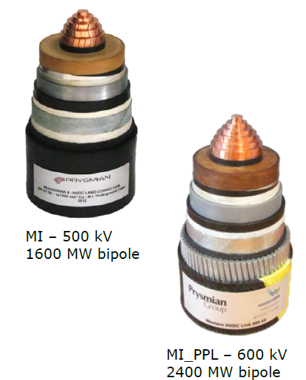
A great achievement in the distribution of HVDC is also due to the progress in cables (since HVDC is often marine projects), which over the past 15 years have increased the available voltage class from 400 to 620 kV
However, the further spread is hampered by the high cost of the power lines of similar caliber (for example, the world's largest power lines PT Xinjiang - Anhui 10 GW per 3000 km will cost the Chinese about 5 billion dollars) and the underdevelopment of equivalent areas of renewable energy generation, i.e. the absence around large consumers (for example, Europe or China) of comparable large consumers at a distance of up to 3-5 thousand km.
Including about 30% of the cost of PTL transmission lines, these are the converter stations.
However, what if the technology of power lines appears at the same time and is cheaper and with less losses (which determine the maximum reasonable length?). For example, power lines with superconducting cable.
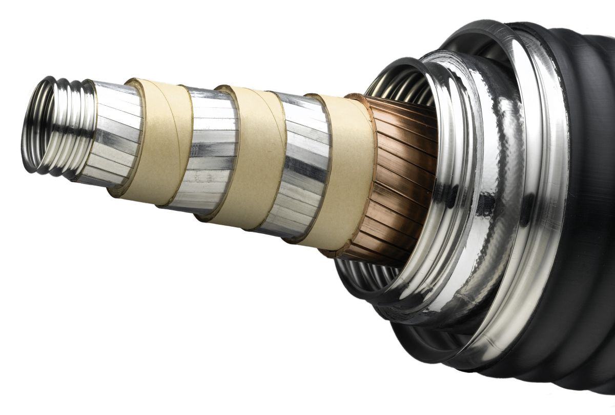
An example of a real superconducting cable for the AMPACITY project. In the center is a former with liquid nitrogen, there are 3 phases of superconducting wire made of high-temperature superconductor tapes, separated by insulation, outside a copper shield, another channel with liquid nitrogen surrounded by multi-layer screen-vacuum insulation inside the vacuum cavity, and outside - a protective polymer sheath .
Of course, the first projects of superconducting power transmission lines and their economic calculations did not appear today or yesterday, but in the early 60s immediately after the discovery of “industrial” superconductors based on niobium intermetallics. However, for classical networks without renewable energy, there was no place for such a JV LEP - both from the point of view of reasonable capacity and cost of such LEP, and from the point of view of the amount of development needed to put them into practice.

The project of the superconducting cable line from 1966 - 100 GW per 1000 km, with a clear underestimation of the cost of the cryogenic part and voltage converters
The economy of a superconducting line is essentially determined by two things: the cost of the superconducting cable and the loss of energy for cooling. The initial idea of using niobium intermetallic compounds stumbled over the high cost of cooling with liquid helium: the internal “cold” electrical assembly should be kept in a vacuum (which is not so difficult) and additionally surrounded by a screen cooled with liquid nitrogen, otherwise the heat flux at 4.2K exceeds the reasonable power of the refrigerators. Such a “sandwich” plus the presence of two expensive cooling systems at one time buried an interest in SP-LEP.
The return to the idea occurred with the discovery of high-temperature conductors and “medium-temperature” magnesium diboride MgB2. Cooling at a temperature of 20 Kelvin (K) for diboride or 70 K (with 70 K - the temperature of liquid nitrogen is widely mastered, and the cost of such a refrigerant is low) for HTSC looks interesting. At the same time, the first superconductor today is fundamentally cheaper than that produced by the methods of the semiconductor industry HTS tapes.

Three single-phase superconducting cables (and inputs to the cryogenic part in the background) of the LIPA project in the USA, each with a current of 2400 A and a voltage of 138 kV, with a total capacity of 574 MW.
Specific figures for today look like this: HTS has a conductor cost of 300-400 dollars per kA * m (i.e., a conductor meter supporting a kiloampere) for liquid nitrogen and 100-130 dollars for 20 K, magnesium diboride for a temperature of 20 K has the cost is $ 2-10 per kA * m (the price is not fixed, as is the technology), titanium niobate is about $ 1 per kA * m, but already for a temperature of 4.2 K. For comparison, aluminum transmission lines cost ~ 5-7 dollars for kA * m, copper - at 20.
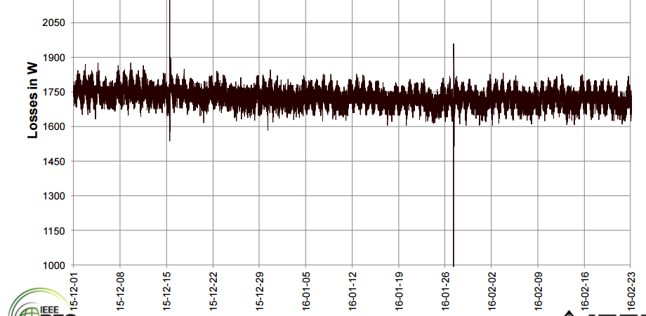
Real heat loss of the AMPACITY cable joint venture with a length of 1 km and a power of ~ 40 MW. In terms of the power of the cryoculler and the circulation pump, the power expended on cable operation is about 35 kW, or less than 0.1% of the transmitted power.
Of course, the fact that a cable joint venture is a complex evacuated product that can only be laid underground adds additional costs, however, where the land under power lines costs a lot of money (for example, in cities), power line joint ventures are already starting to appear, let them in the form of pilot projects. Basically, these are cables from HTS (as most developed), low and medium voltages (from 10 to 66 kV), with currents from 3 to 20 kA. This scheme minimizes the number of intermediate elements associated with increasing the voltage in the trunk (transformers, switches, etc.). The most ambitious and already implemented project of the power cable is the LIPA project: three cables of 650 m length, designed for the transmission of three-phase current with a capacity of 574 MVA, which is comparable to a 330 kV overhead power line. Commissioning of the most powerful HTSC cable line to date took place on June 28, 2008.
An interesting project AMPACITY implemented in Essen, Germany. The medium voltage cable (10 kV with a current of 2300 A and 40 MVA) with an integrated superconducting current limiter (this is an actively developing interesting technology that allows, due to the loss of superconductivity, it is “natural” to disconnect the cable in the event of short-circuit overloads). The launch was made in April 2014. This cable will become a prototype for other projects planned in Germany to replace 110 kV power transmission lines with superconducting 10 kV cables.
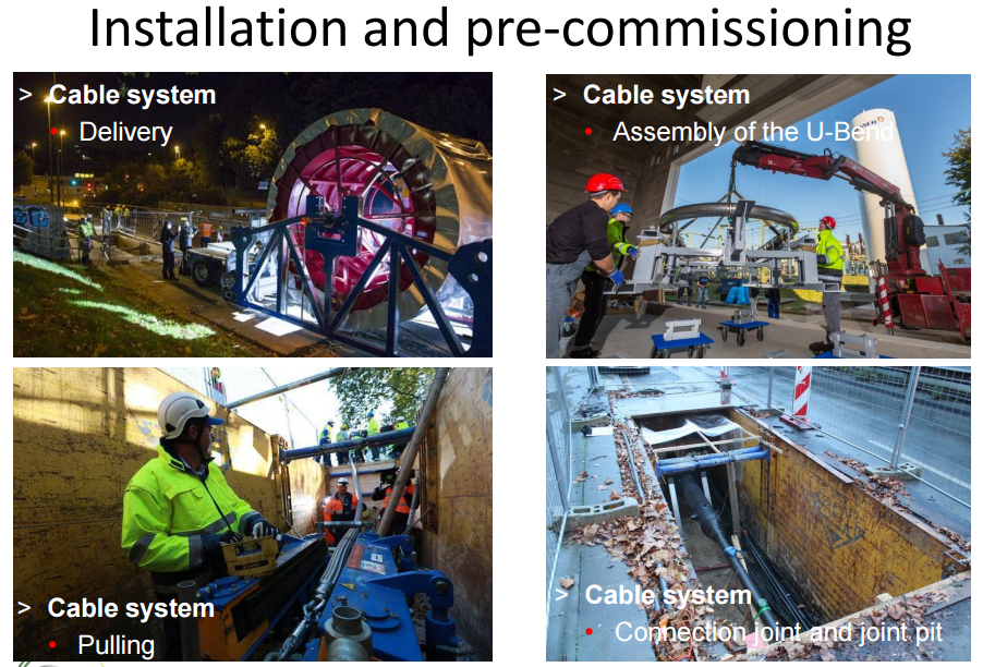
Installing the AMPACITY cable is comparable to pulling conventional high-voltage cables.
There are even more experimental projects with different superconductors for different values of current and voltage, including several in our country, for example, testing experimental 30-meter cable with MgB2 superconductor cooled by liquid hydrogen. The cable for direct current of 3500 A and the voltage of 50 kV created by VNIIKP is interesting with the “hybrid scheme”, where hydrogen cooling is at the same time a promising method of transporting hydrogen as part of the idea of “hydrogen energy”.

But back to renewables. LUT modeling was aimed at creating 100% of renewable energy generation on a continental scale, while the cost of electricity should have been less than $ 100 per MW * h. The peculiarity of the model is in the resulting flows of tens of gigawatts between European countries. Such power is almost impossible to transfer in any way except for the SP of direct current lines.
The LUT modeling data for the UK requires the export of electricity, reaching up to 70 GW, if today there are 3.5 GW island links and expansion of this value to 10 GW in the foreseeable future.
And similar projects exist. For example, Carlo Rubbia, familiar to us from the reactor with the MYRRHA accelerator driver , is promoting projects based on almost the only producer of magnesium diboride strands in the world today - a cryostat with a diameter of 40 cm (however, the diameter is rather difficult for transportation and laying on land) ) holds 2 cables with a current of 20 kA and a voltage of + -250 kV, i.e. A total capacity of 10 GW, and in such a cryostat can be placed 4 conductors = 20 GW, is already close to the required model LUT, and unlike the usual high-voltage DC lines, there is still a large margin for increasing power. Power consumption for refrigeration and pumping of hydrogen will be ~ 10 megawatts per 100 km, or 300 MW per 3000 km - about three times less than for the most advanced high-voltage DC lines.
Rubbia's offer for a 10-gigawatt cable transmission line. Such a gigantic pipe size for liquid hydrogen is needed in order to reduce the hydraulic resistance and to be able to put intermediate cryo-stations no more than 100 km away. There is a problem with maintaining a vacuum on such a pipe (a distributed ion vacuum pump is not the wisest decision here, IMHO)
If you further increase the size of the cryostat to values typical for gas pipelines (1200 mm), and lay 6-8 conductors inside 20 kA and 620 kV (the maximum voltage used for cables today), then the power of such a “pipe” will be 100 GW, that exceeds the power transmitted by the gas and oil pipelines (the most powerful of which transmit the equivalent of 85 GW of heat). The main problem can be connecting such a trunk to existing networks, but the fact is that the technology itself is almost available.
It is interesting to estimate the cost of such a line.
The construction part will obviously dominate. For example, laying 800 km 4 of HVDC cables in the German Sudlink project would cost about 8–10 billion euros (this is known because the project went up from 5 to 15 billion after switching from overhead to cable). The cost of laying 10-12 million euros per km is about 4-4.5 times higher than the average cost of laying gas pipelines, according to this study .

In principle, nothing prevents the use of such equipment for the construction of super-power lines, however, the main difficulties here are visible in the terminal stations and connecting to existing networks
If you take something between gas and cables (ie, 6-8 million euros per km), then the cost of the superconductor is likely to be lost in the cost of construction: for a 100-GW line, the cost of the joint venture will be ~ 0.6 million dollars per 1 km, if you take the joint venture cost $ 2 per kA * m.
An interesting dilemma emerges: the “mega-trunk” joint ventures are several times more expensive than gas pipelines with comparable power (let me remind you that this is all in the future. Today the situation is even worse - you need to pay off R & D at SP-LEP), and that’s why gas pipelines are being built, but not -LEP However, as RES grows, this technology may become attractive and develop rapidly. Already today, the project Sudlink, perhaps would be carried out in the form of a joint venture cable, if the technology would be ready.
Well, we will follow the development of this industry.
PS Thanks to Vitaly Sergeyevich Vysotsky for help with real figures of the cost of superconductors and additional materials!
SES of this kind were to become the main European renewable energy.
The project existed for about 10 years, and then was abandoned by the founding concerns, since the reality of European green energy turned out to be completely different and more prosaic - Chinese photovoltaics and ground-based wind generation in Europe itself, and the idea of drawing energy lines through Libya and Syria is too optimistic .
')
Planned as part of desertec power lines: three main areas with a capacity of 3x10 gigawatts (in the picture one of the weaker versions with 3x5) and several submarine cables.
However, powerful power lines appeared in the desertec project not accidentally (funny, by the way, the land area under power lines in the project produced more land under SES) - this is one of the key technologies that can allow RES generation to grow to an overwhelming proportion, and vice versa: in the absence of energy transfer technology over long distances, renewable energy sources may well be doomed to no more than a share of 30-40% in the European power industry.
Mutual synergy of transcontinental power lines and renewable energy is quite clearly visible on models (for example, in the giant LUT model , as well as in the Vyacheslav Laktushin model ): the unification of many wind-generation regions that are 1-2-3 thousand kilometers apart destroy each other. generation (dangerous total failures) and evens the amount of energy entering the system. The only question is, at what price and with what losses is it possible to transfer energy over such distances. The answer depends on different technologies, which today are essentially three: transmission by alternating current, direct current and superconducting wire. Although such a division is a bit wrong (a superconductor can be with alternating and direct current), but from a system point of view it is legitimate.
However, the technique for high voltage transmission, in my opinion, is one of the most fantastic looking. The photo shows a 600 kV rectifier station.
From the very beginning, traditional electric power industry followed the path of uniting electricity generation with the help of high-voltage alternating current power lines, having reached 750-800-kilovolt transmission lines in the 70s, capable of transmitting 2-3 gigawatts of power. Such power lines come to the limits of the capabilities of classic AC networks: on the one hand, system limitations related to the complexity of synchronization of networks thousands of kilometers long and the desire to divide them into power regions connected by relatively small insuring lines, and on the other hand, the increase in reactive power and the loss of such a line (due to the fact that the inductance of the line and capacitive coupling to the ground).
The picture is not quite typical in the power industry of Russia at the time of writing this article, but usually the flows between areas do not exceed 1-2 GW.
However, the appearance of the power systems of the 70s-80s did not require high-power and long-distance power lines - the power station was most often more convenient to push towards consumers, and the only exception was the renewable energy sources - hydrogeneration.
Hydroelectric power plants, and specifically the Brazilian Itaipu HPP project in the mid-80s, led to the emergence of a new champion in the transmission of electricity a lot and far away - direct current lines. The power of the Brazilian link is 2x 3150 MW at a voltage of +600 kV at a distance of 800 km, the project is implemented by ABB. Such capacities are still on the verge of available AC power lines, but the greater losses paid for the project with conversion to direct current.
Itaipu HPP with a capacity of 14 GW is still the second in the world in terms of HPP capacity. A portion of the energy produced is transmitted via the HVDC link to the area of San Paolo and Rio de Geineiro.
Unlike AC power lines, power lines PT are free from inductive and capacitive losses (i.e., losses through the parasitic capacitive and inductive connection of the conductor with the surrounding earth and water), and were actively used primarily by connecting submarine cables to the general grid of large islands where the loss of the AC line in the water could reach 50-60% of power. In addition, the PTL transmission lines with the same voltage level and wire cross section are capable of transmitting 15% more power through two wires than three AC transmission lines. The problems with insulation in power lines PT are simpler - in fact, at an alternating current, the maximum voltage amplitude is 1.41 times greater than the current, for which power is considered. Finally, PT PTL does not require synchronization of generators on two sides, and therefore eliminates many problems associated with synchronization of remote areas.
Comparison of AC (AC) and DC (DC) current. The comparison is a bit advertising, because with the same current (say, 4000 A), 800 kV AC power lines will have a power of 5.5 GW versus 6.4 GW of DC power lines, but with twice the losses. With equal losses, power will really be 2 times different.
Calculation of losses for different power transmission lines, which were supposed to be used in the project Desertec.
Of course, there are downsides, and significant. First, the direct current in the AC power system requires rectification on the one hand and “twisting” (ie, generating a synchronous sine) on the other. When it comes to many gigawatts and hundreds of kilovolts - this is done by very nontrivial (and very beautiful!) Equipment, which costs many hundreds of millions of dollars. In addition, until the beginning of the 2010s, PTL PTs could only be of the “point-to-point” type, since there were no adequate switches for such DC voltages and powers, which means that with many consumers, it was impossible to cut off one of them with a short circuit - just pay off the whole system. This means that the main use of high-power transmission lines PT is the connection of two energy districts where large power flows were needed. Just a few years ago, ABB (one of the three leaders in the creation of HVDC equipment) managed to create a “hybrid” thyristor-mechanical switch (similar in ideas to the ITER switchboard) that is capable of such work, and the first high-voltage power transmission line PT multi-point "North-East Angra in India.
The ABB hybrid switch is not expressive enough (and not very illuminated), but there is a megaphos Hindu video on the assembly of a mechanical switch for a voltage of 1200 kV - an impressive machine!
Nevertheless, the PT-energy technology developed and became cheaper (largely due to the development of power semiconductors), and by the advent of gigawatts, RES-generation was quite ready to start connecting remote powerful hydroelectric power stations and wind farms to consumers. Especially many such projects have been implemented in recent years in China and India.
However, the thought goes further. In many models, PT-LEP power transmission capabilities are used to equalize renewable energy variability, which is a major factor in the implementation of 100% renewable energy sources in large power systems. Moreover, this approach is already being implemented in practice: you can give an example of a 1.4-gigawatt link Germany-Norway, designed to compensate for the variability of German wind generation by the Norwegian power stations and hydroelectric power stations and the 500 megawatt link Australia-Tasmania needed to maintain the power system of Tasmania (mainly working on hydroelectric power plants) in drought conditions.
A great achievement in the distribution of HVDC is also due to the progress in cables (since HVDC is often marine projects), which over the past 15 years have increased the available voltage class from 400 to 620 kV
However, the further spread is hampered by the high cost of the power lines of similar caliber (for example, the world's largest power lines PT Xinjiang - Anhui 10 GW per 3000 km will cost the Chinese about 5 billion dollars) and the underdevelopment of equivalent areas of renewable energy generation, i.e. the absence around large consumers (for example, Europe or China) of comparable large consumers at a distance of up to 3-5 thousand km.
Including about 30% of the cost of PTL transmission lines, these are the converter stations.
However, what if the technology of power lines appears at the same time and is cheaper and with less losses (which determine the maximum reasonable length?). For example, power lines with superconducting cable.
An example of a real superconducting cable for the AMPACITY project. In the center is a former with liquid nitrogen, there are 3 phases of superconducting wire made of high-temperature superconductor tapes, separated by insulation, outside a copper shield, another channel with liquid nitrogen surrounded by multi-layer screen-vacuum insulation inside the vacuum cavity, and outside - a protective polymer sheath .
Of course, the first projects of superconducting power transmission lines and their economic calculations did not appear today or yesterday, but in the early 60s immediately after the discovery of “industrial” superconductors based on niobium intermetallics. However, for classical networks without renewable energy, there was no place for such a JV LEP - both from the point of view of reasonable capacity and cost of such LEP, and from the point of view of the amount of development needed to put them into practice.
The project of the superconducting cable line from 1966 - 100 GW per 1000 km, with a clear underestimation of the cost of the cryogenic part and voltage converters
The economy of a superconducting line is essentially determined by two things: the cost of the superconducting cable and the loss of energy for cooling. The initial idea of using niobium intermetallic compounds stumbled over the high cost of cooling with liquid helium: the internal “cold” electrical assembly should be kept in a vacuum (which is not so difficult) and additionally surrounded by a screen cooled with liquid nitrogen, otherwise the heat flux at 4.2K exceeds the reasonable power of the refrigerators. Such a “sandwich” plus the presence of two expensive cooling systems at one time buried an interest in SP-LEP.
The return to the idea occurred with the discovery of high-temperature conductors and “medium-temperature” magnesium diboride MgB2. Cooling at a temperature of 20 Kelvin (K) for diboride or 70 K (with 70 K - the temperature of liquid nitrogen is widely mastered, and the cost of such a refrigerant is low) for HTSC looks interesting. At the same time, the first superconductor today is fundamentally cheaper than that produced by the methods of the semiconductor industry HTS tapes.
Three single-phase superconducting cables (and inputs to the cryogenic part in the background) of the LIPA project in the USA, each with a current of 2400 A and a voltage of 138 kV, with a total capacity of 574 MW.
Specific figures for today look like this: HTS has a conductor cost of 300-400 dollars per kA * m (i.e., a conductor meter supporting a kiloampere) for liquid nitrogen and 100-130 dollars for 20 K, magnesium diboride for a temperature of 20 K has the cost is $ 2-10 per kA * m (the price is not fixed, as is the technology), titanium niobate is about $ 1 per kA * m, but already for a temperature of 4.2 K. For comparison, aluminum transmission lines cost ~ 5-7 dollars for kA * m, copper - at 20.
Real heat loss of the AMPACITY cable joint venture with a length of 1 km and a power of ~ 40 MW. In terms of the power of the cryoculler and the circulation pump, the power expended on cable operation is about 35 kW, or less than 0.1% of the transmitted power.
Of course, the fact that a cable joint venture is a complex evacuated product that can only be laid underground adds additional costs, however, where the land under power lines costs a lot of money (for example, in cities), power line joint ventures are already starting to appear, let them in the form of pilot projects. Basically, these are cables from HTS (as most developed), low and medium voltages (from 10 to 66 kV), with currents from 3 to 20 kA. This scheme minimizes the number of intermediate elements associated with increasing the voltage in the trunk (transformers, switches, etc.). The most ambitious and already implemented project of the power cable is the LIPA project: three cables of 650 m length, designed for the transmission of three-phase current with a capacity of 574 MVA, which is comparable to a 330 kV overhead power line. Commissioning of the most powerful HTSC cable line to date took place on June 28, 2008.
An interesting project AMPACITY implemented in Essen, Germany. The medium voltage cable (10 kV with a current of 2300 A and 40 MVA) with an integrated superconducting current limiter (this is an actively developing interesting technology that allows, due to the loss of superconductivity, it is “natural” to disconnect the cable in the event of short-circuit overloads). The launch was made in April 2014. This cable will become a prototype for other projects planned in Germany to replace 110 kV power transmission lines with superconducting 10 kV cables.
Installing the AMPACITY cable is comparable to pulling conventional high-voltage cables.
There are even more experimental projects with different superconductors for different values of current and voltage, including several in our country, for example, testing experimental 30-meter cable with MgB2 superconductor cooled by liquid hydrogen. The cable for direct current of 3500 A and the voltage of 50 kV created by VNIIKP is interesting with the “hybrid scheme”, where hydrogen cooling is at the same time a promising method of transporting hydrogen as part of the idea of “hydrogen energy”.
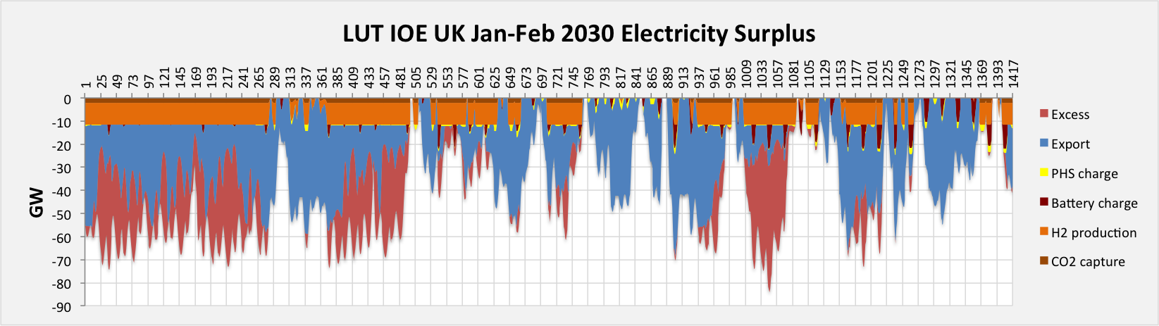
But back to renewables. LUT modeling was aimed at creating 100% of renewable energy generation on a continental scale, while the cost of electricity should have been less than $ 100 per MW * h. The peculiarity of the model is in the resulting flows of tens of gigawatts between European countries. Such power is almost impossible to transfer in any way except for the SP of direct current lines.
The LUT modeling data for the UK requires the export of electricity, reaching up to 70 GW, if today there are 3.5 GW island links and expansion of this value to 10 GW in the foreseeable future.
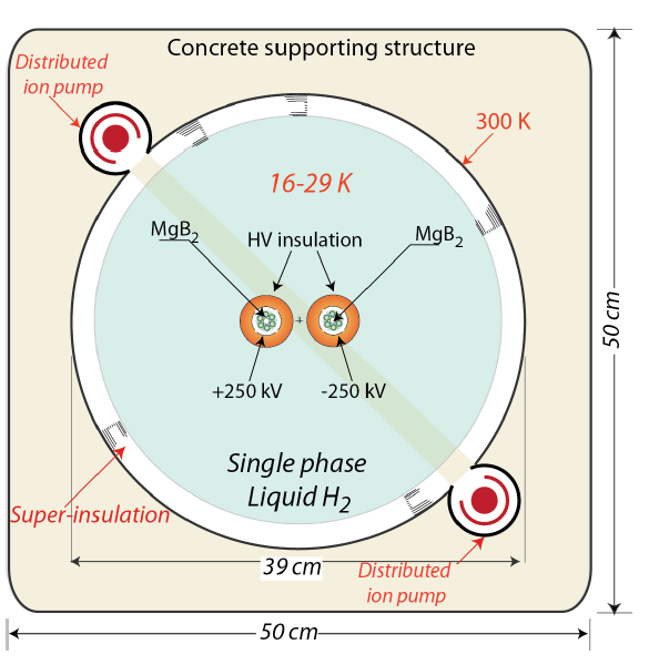
And similar projects exist. For example, Carlo Rubbia, familiar to us from the reactor with the MYRRHA accelerator driver , is promoting projects based on almost the only producer of magnesium diboride strands in the world today - a cryostat with a diameter of 40 cm (however, the diameter is rather difficult for transportation and laying on land) ) holds 2 cables with a current of 20 kA and a voltage of + -250 kV, i.e. A total capacity of 10 GW, and in such a cryostat can be placed 4 conductors = 20 GW, is already close to the required model LUT, and unlike the usual high-voltage DC lines, there is still a large margin for increasing power. Power consumption for refrigeration and pumping of hydrogen will be ~ 10 megawatts per 100 km, or 300 MW per 3000 km - about three times less than for the most advanced high-voltage DC lines.
Rubbia's offer for a 10-gigawatt cable transmission line. Such a gigantic pipe size for liquid hydrogen is needed in order to reduce the hydraulic resistance and to be able to put intermediate cryo-stations no more than 100 km away. There is a problem with maintaining a vacuum on such a pipe (a distributed ion vacuum pump is not the wisest decision here, IMHO)
If you further increase the size of the cryostat to values typical for gas pipelines (1200 mm), and lay 6-8 conductors inside 20 kA and 620 kV (the maximum voltage used for cables today), then the power of such a “pipe” will be 100 GW, that exceeds the power transmitted by the gas and oil pipelines (the most powerful of which transmit the equivalent of 85 GW of heat). The main problem can be connecting such a trunk to existing networks, but the fact is that the technology itself is almost available.
It is interesting to estimate the cost of such a line.
The construction part will obviously dominate. For example, laying 800 km 4 of HVDC cables in the German Sudlink project would cost about 8–10 billion euros (this is known because the project went up from 5 to 15 billion after switching from overhead to cable). The cost of laying 10-12 million euros per km is about 4-4.5 times higher than the average cost of laying gas pipelines, according to this study .
In principle, nothing prevents the use of such equipment for the construction of super-power lines, however, the main difficulties here are visible in the terminal stations and connecting to existing networks
If you take something between gas and cables (ie, 6-8 million euros per km), then the cost of the superconductor is likely to be lost in the cost of construction: for a 100-GW line, the cost of the joint venture will be ~ 0.6 million dollars per 1 km, if you take the joint venture cost $ 2 per kA * m.
An interesting dilemma emerges: the “mega-trunk” joint ventures are several times more expensive than gas pipelines with comparable power (let me remind you that this is all in the future. Today the situation is even worse - you need to pay off R & D at SP-LEP), and that’s why gas pipelines are being built, but not -LEP However, as RES grows, this technology may become attractive and develop rapidly. Already today, the project Sudlink, perhaps would be carried out in the form of a joint venture cable, if the technology would be ready.
Well, we will follow the development of this industry.
PS Thanks to Vitaly Sergeyevich Vysotsky for help with real figures of the cost of superconductors and additional materials!
Source: https://habr.com/ru/post/373395/
All Articles