Electron microscope in the garage. Cathode and gun
If you have missed previous issues - be sure to read .
Sufficient vacuum ( Torr) has already been received, which means it is time to move on: install the cathode, deal with the high-voltage power supply and finally start up electrons!
')
This is how cathodes and an electron gun with a focusing electrode look like in reality. Under the cut is a simple explanation of how this works, as well as the insides of an electron-optical column in 4K quality.
 In a scanning electron microscope, the sample under investigation is sequentially point-by-point irradiated with a thin electron beam, and it is highly desirable that they also move with equal speed. To create such an electron beam, an electron-optical column with a whole system of electrostatic and electromagnetic lenses serves. And the first element in it is an electron gun .
The well-known scientist in the field of electron optics and electron microscopy, Peter W. Hawkes, in his book Electron optics and electron microscopy (1972), gives such a scheme of an electron gun (see the figure on the left).
The direct source of free electrons, from which that thin beam is then formed, is the cathode .
 Such electrons are obtained due to the phenomenon of thermionic emission . Generally speaking, there is still autoemission , and it is used in modern microscopes, but its use is fraught with additional difficulties, therefore we will not consider it yet.
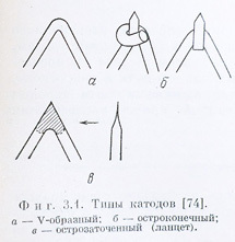
Thermionic emission is very simple: the cathode is a tungsten wire, bent in the form of a Latin letter V, and heated by passing an electric current through it. For completeness, here is another illustration from the above book, which demonstrates the different types of cathodes used in electron microscopes.
For understanding (and calculations) it is convenient when they say that the anode is a positive electrode and the cathode is negative, but in an electron microscope the anode is the entire column. Serving high voltages of tens of kilovolts to her is a bad idea. Therefore, they do it differently: the column (ie, the anode) is grounded, and a negative high voltage is applied to the cathode and the heating current is mixed in.
The resulting electron beam must be further prepared before sending it to electromagnetic lenses. Historically, the whole design of a thermionic electron gun has undergone little change and consists of a cathode, a focusing electrode, called a venelt, and an anode.
The moment when it will be necessary to try the electron gun and electromagnetic lenses in the work closer and closer, so I decided to conduct a total inspection of the entire column.
This became possible only after good people gave me a jar of high-vacuum grease (more on this in thanks). And, as it turned out, the column was being dismantled for good reason. Found and fixed there a few problems. And filmed everything in 4K quality. You can enjoy the internal structure of the microscope.
The first video is a bit long, I did not mount it.
People who watched this video on my channel before publishing the article were asked to make the next part more eventful and shorter. He did so, cut out unnecessary moments, accelerated all sorts of loosening-tightening screws and laid out the second video about the disassembly of the column. There you can see all the beauty of the bottom of the electron microscope - deflecting coils, stigmator, diaphragm.
What is not included in the video is the objective aperture and fixing of the object table.
It stands in the pole tip of an objective lens, and works in essence, like a diaphragm in a camera. Want a greater depth of field - you need to choose the smallest hole. If you want maximum intensity of the beam - choose the largest hole.
As you can tell, everything is more or less in order. Well, see for yourself:

Crumpled, dirty, but all the wires in place, adjustments work. It's good! Traditional wash, straighten, lubricate the gasket and forward.
In this microscope, there are three apertures available on a single strip (presumably a platinum foil).
Here is what the official manual for the microscope says on this topic:
I have long wanted to get to the table, but there was no reason. And here he was found. It turned out that the wiring connecting the vacuum input for the absorbed current sensor and the table itself is broken. Not that it broke off, but in general there is no whole piece of wire. But at the same time and everything else is quite dirty. See what it looked like before:
And here is what it looks like after a little maintenance:
From what to make the wire - it was a big question. Normal wire can not be, because insulation will evaporate in a vacuum, and it will not lead to anything good. Even the material of the conductor itself is important, usually oxygen-free copper is used in such cases.
After much thought, an option was found with a special fiberglass tube, which is used as a heat shield for wires. It is unlikely to evaporate, but just in case washed it in isopropyl alcohol from pollution. And inside he started a copper conductor from a twisted pair, which is made of the same oxygen-free copper (correct if I am mistaken).
Last time I wrote a list of what will help in this project, which will be useful for experiments. Many thanks to all who responded! I visited several universities and organizations, met very interesting people.
For the implementation of projects received very important components. For example, a small turbomolecular pump with a controller:

I think that after the final debugging of the vacuum system of the microscope, I replace the oil pump with this turbomolecular one.
I also got a jar of high-vacuum non-silicone Apiezon grease, which opened up the possibility for me to finally go through the entire column and fix all the problems I wrote about above.
Thank you Goron_Dekar ! I am very enthusiastic after our communication. I will definitely come back to talk, and try to bring something useful.
I thank Victor from the Moscow Institute of Physics and Technology, it was a useful and exciting journey to go to Pushchino. They have a slightly older model of this kind of JEOL working in micro-analyzer mode there.
ZavDimka - thanks for the interesting and useful things (although I haven’t taken them yet :)).
This person makes an excellent high voltage power supply. And much more. And since the microscope is already moving into the electronics stage, this is now very relevant.
jar_ohty - even though I haven’t gone to your place yet, I’m happy to visit to meet you. Maybe we can use the secondary electronic multiplier :)
And many more people, who are also very grateful. Detectors and cathodes for the microscope are still looking, but there is some hope.
In the next series - we light the cathode :)
Sufficient vacuum ( Torr) has already been received, which means it is time to move on: install the cathode, deal with the high-voltage power supply and finally start up electrons!
')
This is how cathodes and an electron gun with a focusing electrode look like in reality. Under the cut is a simple explanation of how this works, as well as the insides of an electron-optical column in 4K quality.
1. Electron gun and cathode
In a scanning electron microscope, the sample under investigation is sequentially point-by-point irradiated with a thin electron beam, and it is highly desirable that they also move with equal speed. To create such an electron beam, an electron-optical column with a whole system of electrostatic and electromagnetic lenses serves. And the first element in it is an electron gun .The well-known scientist in the field of electron optics and electron microscopy, Peter W. Hawkes, in his book Electron optics and electron microscopy (1972), gives such a scheme of an electron gun (see the figure on the left).
The direct source of free electrons, from which that thin beam is then formed, is the cathode .
Such electrons are obtained due to the phenomenon of thermionic emission . Generally speaking, there is still autoemission , and it is used in modern microscopes, but its use is fraught with additional difficulties, therefore we will not consider it yet.Thermionic emission is very simple: the cathode is a tungsten wire, bent in the form of a Latin letter V, and heated by passing an electric current through it. For completeness, here is another illustration from the above book, which demonstrates the different types of cathodes used in electron microscopes.
For understanding (and calculations) it is convenient when they say that the anode is a positive electrode and the cathode is negative, but in an electron microscope the anode is the entire column. Serving high voltages of tens of kilovolts to her is a bad idea. Therefore, they do it differently: the column (ie, the anode) is grounded, and a negative high voltage is applied to the cathode and the heating current is mixed in.
The resulting electron beam must be further prepared before sending it to electromagnetic lenses. Historically, the whole design of a thermionic electron gun has undergone little change and consists of a cathode, a focusing electrode, called a venelt, and an anode.
2. Dismantling the entire column
The moment when it will be necessary to try the electron gun and electromagnetic lenses in the work closer and closer, so I decided to conduct a total inspection of the entire column.
This became possible only after good people gave me a jar of high-vacuum grease (more on this in thanks). And, as it turned out, the column was being dismantled for good reason. Found and fixed there a few problems. And filmed everything in 4K quality. You can enjoy the internal structure of the microscope.
The first video is a bit long, I did not mount it.
Summary-investigation of the first part
He began to disassemble the electron gun, removed the anode, the upper part of the column and saw quite a lot of debris (dust, fingerprints, grease). But this is not the worst, the saddest thing is that someone has already climbed there, and not very capable hands. I disassembled, disassembled, and the signs that they climbed there were everywhere.
As a result, it turned out that the heads of the two screws were completely torn off, and others, which are longer in length, were put in their place, and they simply rested against the body. Therefore, the anode was crooked. To compensate for this (and they apparently did not notice that the anode was at an angle), the condenser lens was also shifted to the side.
Moreover, when they put the condenser lens back, they didn’t fall into the corresponding adjustment grooves at all, so it was very difficult to carry out a smooth adjustment, as planned by the manufacturer.
By the way, I say in the video condenser lens for unusual. Seen in one old book so called. I read it later and it turned out that the words condenser and condenser are synonyms, and even earlier a conventional capacitor was called a condenser. But now the terminology is such that a capacitor is called a capacitor, and a collecting electromagnetic lens is called a condenser lens or simply a condenser.
People who watched this video on my channel before publishing the article were asked to make the next part more eventful and shorter. He did so, cut out unnecessary moments, accelerated all sorts of loosening-tightening screws and laid out the second video about the disassembly of the column. There you can see all the beauty of the bottom of the electron microscope - deflecting coils, stigmator, diaphragm.
Summary-investigation of the second part
I decided to make out everything "to the ground, and then ...". I saw that the previous owners also dismantled everything to the ground. Missed all-all gaskets with vacuum grease, even those that did not need to smear. They also slightly damaged the stigmator windings when they inserted it back, but this was not critical. Straightened, put them back, should work. Oriented the deflection coils correctly, sort of.
What is not included in the video is the objective aperture and fixing of the object table.
3. Objective lens aperture
It stands in the pole tip of an objective lens, and works in essence, like a diaphragm in a camera. Want a greater depth of field - you need to choose the smallest hole. If you want maximum intensity of the beam - choose the largest hole.
As you can tell, everything is more or less in order. Well, see for yourself:
Crumpled, dirty, but all the wires in place, adjustments work. It's good! Traditional wash, straighten, lubricate the gasket and forward.
In this microscope, there are three apertures available on a single strip (presumably a platinum foil).
Here is what the official manual for the microscope says on this topic:
- 100 µm - for observations that require a large depth of field or low beam intensity
- 200 microns - for normal applications
- 600 microns - for X-ray analyzer or real-time observations
4. Subject table
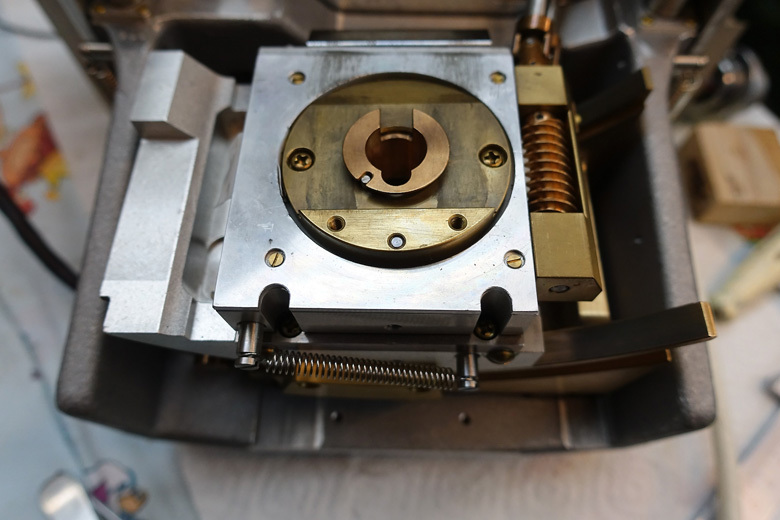
I have long wanted to get to the table, but there was no reason. And here he was found. It turned out that the wiring connecting the vacuum input for the absorbed current sensor and the table itself is broken. Not that it broke off, but in general there is no whole piece of wire. But at the same time and everything else is quite dirty. See what it looked like before:
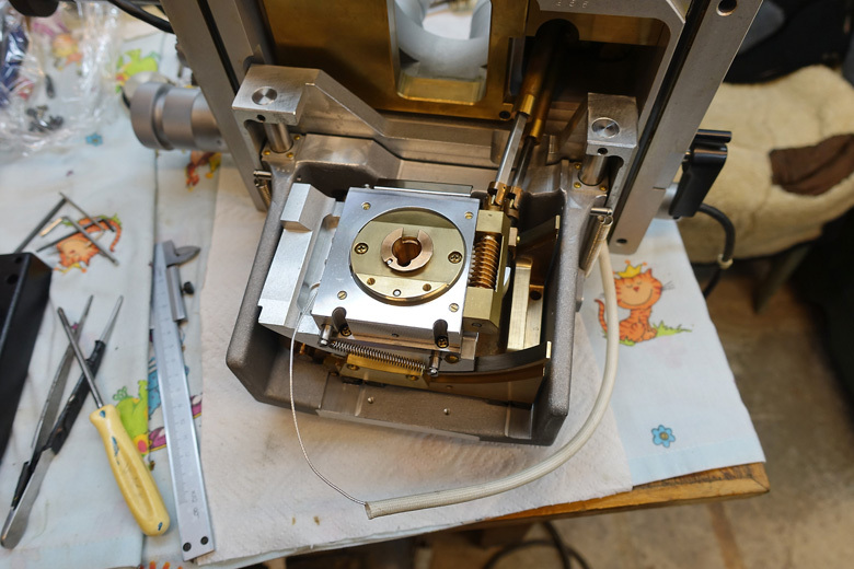
And here is what it looks like after a little maintenance:
From what to make the wire - it was a big question. Normal wire can not be, because insulation will evaporate in a vacuum, and it will not lead to anything good. Even the material of the conductor itself is important, usually oxygen-free copper is used in such cases.
After much thought, an option was found with a special fiberglass tube, which is used as a heat shield for wires. It is unlikely to evaporate, but just in case washed it in isopropyl alcohol from pollution. And inside he started a copper conductor from a twisted pair, which is made of the same oxygen-free copper (correct if I am mistaken).
Thank!
Last time I wrote a list of what will help in this project, which will be useful for experiments. Many thanks to all who responded! I visited several universities and organizations, met very interesting people.
For the implementation of projects received very important components. For example, a small turbomolecular pump with a controller:
I think that after the final debugging of the vacuum system of the microscope, I replace the oil pump with this turbomolecular one.
I also got a jar of high-vacuum non-silicone Apiezon grease, which opened up the possibility for me to finally go through the entire column and fix all the problems I wrote about above.
Thank you Goron_Dekar ! I am very enthusiastic after our communication. I will definitely come back to talk, and try to bring something useful.
I thank Victor from the Moscow Institute of Physics and Technology, it was a useful and exciting journey to go to Pushchino. They have a slightly older model of this kind of JEOL working in micro-analyzer mode there.
ZavDimka - thanks for the interesting and useful things (although I haven’t taken them yet :)).
This person makes an excellent high voltage power supply. And much more. And since the microscope is already moving into the electronics stage, this is now very relevant.
jar_ohty - even though I haven’t gone to your place yet, I’m happy to visit to meet you. Maybe we can use the secondary electronic multiplier :)
And many more people, who are also very grateful. Detectors and cathodes for the microscope are still looking, but there is some hope.
In the next series - we light the cathode :)
Source: https://habr.com/ru/post/373273/
All Articles