Evaluation of low frequency methods on the Arduino
The task, in fact, arose from the need to read the rotational speed of the obturator with an optical sensor mounted on a homemade cup anemometer. How many holes there are not drilled around the circumference, but when the wind is weak, the frequency from the output of the sensor will be a few hertz (especially if the sensor is well balanced and lightened to reduce the threshold for moving off to the maximum).
Puzzled by this question, I first found out that standard libraries in this regard do not offer anything good. There is, of course, FreqMeasure and FreqPeriod , but I did not like them at first glance: unnecessarily complicated, and also with almost completely missing documentation. To top it all, the examples attached to them simply didn’t work for me the first time (I guess why, but didn’t bother - it’s not interesting to dig into someone else’s blunders).
I had to do it myself. Low frequencies must be measured after a period, because the ideal end result is something like the function pulseIn (), which only measures not the pulse duration, but the period. There were several options that I propose to the audience in the hope that they will be useful to someone. For each option, the limits of applicability were determined and advantages and disadvantages were considered in comparison with each other.
At first I got stuck on the pulseIn () function and couldn’t it be adapted to this case? In the depths of the Arduino folders (in the wiring_pulse.c file), its more advanced version was found, called pulseInLong (). It was introduced, as I found out, somewhere around version 1.6.5, but I don’t understand what this option is better than the original function. Judging by the fact that the function is not entered in the official list - or nothing, or has some unexplained restrictions. But its structure seemed to me more transparent and easier to be altered in the right direction. The function call looks like pulseIn ():
')
In the function, three conditionally infinite loops (with forced output at the specified timeout) work in succession. In the first cycle, a drop is expected to the state specified by the state parameter (HIGH or LOW) - in order to skip the current pulse, in the middle of which we may have hit. In the second, the beginning of the next period is expected (reverse), after which the number of microseconds at the start is determined. Finally, the third cycle is the measuring cycle, the difference in the state state is expected again, the difference in the number of microseconds is fixed and returned in the function value.
Alteration consists in the fact that after the third cycle the number of microseconds is not fixed, but the fourth cycle, identical to the second, is added. And only after reaching the same differential again as at the start, the number of microseconds is fixed and returned in the function value. Thus we get the duration of the period. A test sketch with a reworked function, which I renamed to periodInLong, looks completely like this (some comments have been left from the original):
Notice the output from Tone_PIN and the commented out function call tone () in the setup () section. This is done to test another circumstance, which is at the end of the article.
To test the operation, pin 8 (randomly selected as IN_PIN) was supplied with a signal from a home-made oscillator based on watch quartz and divider counter 561IE16. At its output, we get frequencies that are multiples of powers of two, from 2 to 2048 Hz, as well as 16384 Hz (and, if desired, another 32768 Hz directly from the generator).
The results of a sample of consecutive measurements for frequencies 2, 8, 64, and also 2048 and 16384 hertz are combined into one table in the figure (the top line is the duration in microseconds, the next is the calculated frequency):
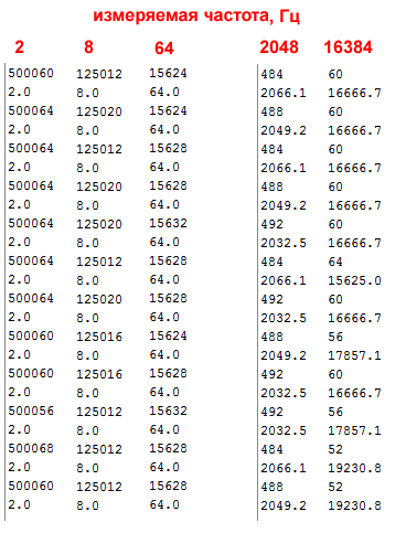
As we can see from this data, the method works quite satisfactorily for low frequencies (below about 100 Hz), but it “rattles” at high frequencies. This is normal if we recall that the micros () function is tied up with overflows and Timer0 counters, and its call and manipulations with a long integer take considerable time. Simple conditionally infinite loops in controllers are in principle not a very reliable thing.
The great advantage of this method is that it allows you to use any digital output of the controller as a measurement. The disadvantage is that the main loop hangs for the duration of the measurement (for units of hertz it is crazy, by the standards of the controller, a fraction of a second) and at the same time it is not very desirable to use some other interrupts. Two other methods are practically devoid of this shortcoming, but they are tied to certain conclusions of the controller.
In fact, this method should be implemented in pure assembler, and not in the Arduino environment, then it would be possible to extend the maximum of it out of it. But even so, given our frequency range in units of tens of hertz, it will turn out well.
The way is that we run a 16-bit Timer1 in two modes at once: account and event capture. When counting, it is convenient to set the clock divider 1/8, then in the 16 MHz controller, we will calculate the time by ticks for half a microsecond. At overflow (65,536 microsecond halves), an overflow interrupt is triggered, which increments the third-digit counter (byte) of a long number. Three byte bits (16777216 halves of a microsecond or about 8 seconds) is quite enough for our purposes of counting a frequency period of the order of a few tens of hertz. By capturing the differential level event, we fix the three-digit number of ticks that have passed from the previous such event (collecting it from the values of the timer registers plus the third most significant bit), reset all variables and counting registers and wait for the next differential. In theory, it would be necessary to clear the clocks predivider counters, but they will still change when Timer0 is working (prescaler for timers 0 and 1 is common), and with a 1/8 divider this error will be insignificant.
A sketch for testing this idea is as follows:
When displaying the results, we took into account that one timer tick is 0.5 microseconds. In addition, a flag is introduced here that prevents the calculation of the calculated period value for the time of the withdrawal. It will not affect the measurement process itself. The large delay at the end of the setup is due to the need to wait some time, otherwise the first measurements will be erroneous. Its minimum value is equal to the period of measured oscillations.
The measurement results for the same frequencies 2, 8, 64, as well as 2048 and 16384 hertz are combined in the table:
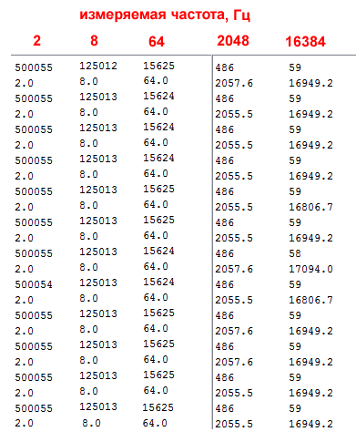
Note that the interval measurements, even for high frequencies, produce fairly stable results, if different from each other, then in the legal unit of the lower order. But for high frequencies, a systematic error of two extra microseconds is noticeable, which makes the frequency values too high. This is probably the effect of simultaneously working Timer0, but for the frequencies we need in units of tens of hertz, the error will not matter. In addition, it is quite easy to take into account in the calculations, if necessary, by calibrating the sketch on an exemplary frequency meter.
This method can be recommended if the need to conduct the most accurate measurements of long periods. Its disadvantage is also obvious: measurements can be carried out only via pin number 8 (pin of PB0 controller).
This is the easiest and most obvious way. We run an external interrupt (by differential on the output) and at the same time fix the system time with the same micros () function. As soon as the second such interruption occurs, we calculate the difference and thus get the period.
There should be more sources of errors here, because the counter and external interrupts are systematically divided and a certain time elapses before fixing the readings. But, first, it can be expected that for large periods they will not matter, and secondly, in reality, it turned out even better than expected.
The sketch that implements this idea looks like this:
The interrupt input here will be different - output number 2 (output PD2). As before, the flag protects against changing the ttime variable during the output process. Regarding the absence of an input frequency, the same considerations as in the previous case are valid here. The results of measuring the same frequencies are presented in the table:
As we can see, here the error in the measurements is in full accordance with the resolution of the micros () function, equal to 4 μs - that is, in fact, the result varies within plus or minus one tick of the system timer, everything is legal. This is not the best effect on the measurements of high frequencies, but for our range is quite suitable. Therefore, this method can be recommended for ordinary applications.
In general, this is a purely cognitive task, probably not having practical applications. But I wondered: what will happen if the measured frequency comes from the controller itself? It is convenient for this to use the tone function (), which occupies Timer2, and, therefore, will not intersect with either the system time or Timer1 if it is used for measurement. That is why in each of the sketches this function is inserted, which works through the output of Tone_PIN.
For each of the sketches, the function was uncommented, and it was first checked whether the parallel operation of the tone () function did not affect the measurements at different combinations of frequencies, both measured and generated. None of the options for explicit influence was noticed. Then the Tone_PIN pin was connected directly to the IN_PIN frequency measurement input and the port monitor was started to monitor the results.
Actually, I expected to see as a result one of two options: a) measurements will work as if nothing had happened; b) or rather, the measurements will lie shamelessly, and with a regular systematic error (which should have been due to the addition of the oscillations of two dependent timers). The reality turned out to be more interesting than the assumptions: the measurements in all three cases worked normally, but in a limited range of specified frequencies. Moreover, the lower limit was determined exactly: the input period was measured correctly, starting from 32 hertz. I did not define the upper limit precisely - it is too troublesome, but approximately it is located somewhat above 1000 Hz. Anything lower or higher is absolutely wrong. And, what is most interesting, without special regularity: the readings in the same series are the same, but after a reboot with the same given values, they become completely different.
I am not going to explain these results, but, probably, this is not very necessary. In practice, such a regime, as I have said, is useless, and if needed, it suffices to recall these empirical patterns.
Puzzled by this question, I first found out that standard libraries in this regard do not offer anything good. There is, of course, FreqMeasure and FreqPeriod , but I did not like them at first glance: unnecessarily complicated, and also with almost completely missing documentation. To top it all, the examples attached to them simply didn’t work for me the first time (I guess why, but didn’t bother - it’s not interesting to dig into someone else’s blunders).
I had to do it myself. Low frequencies must be measured after a period, because the ideal end result is something like the function pulseIn (), which only measures not the pulse duration, but the period. There were several options that I propose to the audience in the hope that they will be useful to someone. For each option, the limits of applicability were determined and advantages and disadvantages were considered in comparison with each other.
Option 1. Rebuild pulseInLong ()
At first I got stuck on the pulseIn () function and couldn’t it be adapted to this case? In the depths of the Arduino folders (in the wiring_pulse.c file), its more advanced version was found, called pulseInLong (). It was introduced, as I found out, somewhere around version 1.6.5, but I don’t understand what this option is better than the original function. Judging by the fact that the function is not entered in the official list - or nothing, or has some unexplained restrictions. But its structure seemed to me more transparent and easier to be altered in the right direction. The function call looks like pulseIn ():
')
unsigned long pulseInLong(uint8_t pin, uint8_t state, unsigned long timeout) In the function, three conditionally infinite loops (with forced output at the specified timeout) work in succession. In the first cycle, a drop is expected to the state specified by the state parameter (HIGH or LOW) - in order to skip the current pulse, in the middle of which we may have hit. In the second, the beginning of the next period is expected (reverse), after which the number of microseconds at the start is determined. Finally, the third cycle is the measuring cycle, the difference in the state state is expected again, the difference in the number of microseconds is fixed and returned in the function value.
Alteration consists in the fact that after the third cycle the number of microseconds is not fixed, but the fourth cycle, identical to the second, is added. And only after reaching the same differential again as at the start, the number of microseconds is fixed and returned in the function value. Thus we get the duration of the period. A test sketch with a reworked function, which I renamed to periodInLong, looks completely like this (some comments have been left from the original):
#define Tone_PIN 12 // – . #define IN_PIN 8 // volatile unsigned long ttime = 0; // unsigned long periodInLong(uint8_t pin, uint8_t state, unsigned long timeout) { // cache the port and bit of the pin in order to speed up the // pulse width measuring loop and achieve finer resolution. calling // digitalRead() instead yields much coarser resolution. uint8_t bit = digitalPinToBitMask(pin); uint8_t port = digitalPinToPort(pin); uint8_t stateMask = (state ? bit : 0); unsigned long startMicros = micros(); // wait for any previous pulse to end while ((*portInputRegister(port) & bit) != stateMask) { if (micros() - startMicros > timeout) return 0; } // wait for the pulse to start while ((*portInputRegister(port) & bit) == stateMask) { if (micros() - startMicros > timeout) return 0; } unsigned long start = micros(); // wait for the pulse to stop while ((*portInputRegister(port) & bit) != stateMask) { if (micros() - startMicros > timeout) return 0; } // wait for the pulse to start while ((*portInputRegister(port) & bit) == stateMask) { if (micros() - startMicros > timeout) return 0; } return micros() - start; } void setup() { pinMode(IR_PIN, OUTPUT); // pinMode(IN_PIN, INPUT); // Serial.begin(9600); // tone(Tone_PIN, 1000); } void loop() { ttime=periodInLong(IN_PIN, LOW, 1000000); // 1 Serial.println(ttime); if (ttime!=0) {// , float f = 1000000/float(ttime); // Serial.println(f,1);} delay(500); } Notice the output from Tone_PIN and the commented out function call tone () in the setup () section. This is done to test another circumstance, which is at the end of the article.
To test the operation, pin 8 (randomly selected as IN_PIN) was supplied with a signal from a home-made oscillator based on watch quartz and divider counter 561IE16. At its output, we get frequencies that are multiples of powers of two, from 2 to 2048 Hz, as well as 16384 Hz (and, if desired, another 32768 Hz directly from the generator).
The results of a sample of consecutive measurements for frequencies 2, 8, 64, and also 2048 and 16384 hertz are combined into one table in the figure (the top line is the duration in microseconds, the next is the calculated frequency):
As we can see from this data, the method works quite satisfactorily for low frequencies (below about 100 Hz), but it “rattles” at high frequencies. This is normal if we recall that the micros () function is tied up with overflows and Timer0 counters, and its call and manipulations with a long integer take considerable time. Simple conditionally infinite loops in controllers are in principle not a very reliable thing.
The great advantage of this method is that it allows you to use any digital output of the controller as a measurement. The disadvantage is that the main loop hangs for the duration of the measurement (for units of hertz it is crazy, by the standards of the controller, a fraction of a second) and at the same time it is not very desirable to use some other interrupts. Two other methods are practically devoid of this shortcoming, but they are tied to certain conclusions of the controller.
Method 2. Ideologically correct: use Timer1
In fact, this method should be implemented in pure assembler, and not in the Arduino environment, then it would be possible to extend the maximum of it out of it. But even so, given our frequency range in units of tens of hertz, it will turn out well.
The way is that we run a 16-bit Timer1 in two modes at once: account and event capture. When counting, it is convenient to set the clock divider 1/8, then in the 16 MHz controller, we will calculate the time by ticks for half a microsecond. At overflow (65,536 microsecond halves), an overflow interrupt is triggered, which increments the third-digit counter (byte) of a long number. Three byte bits (16777216 halves of a microsecond or about 8 seconds) is quite enough for our purposes of counting a frequency period of the order of a few tens of hertz. By capturing the differential level event, we fix the three-digit number of ticks that have passed from the previous such event (collecting it from the values of the timer registers plus the third most significant bit), reset all variables and counting registers and wait for the next differential. In theory, it would be necessary to clear the clocks predivider counters, but they will still change when Timer0 is working (prescaler for timers 0 and 1 is common), and with a 1/8 divider this error will be insignificant.
Details for the curious: why is this method ideologically correct
This method is ideologically correct because everything happens within a single timer, which is not affected by anything else: the score is mostly hardware. In principle, some error can occur here only when the timer interrupt call is delayed due to a match with some other interrupt. But this is generally so incredible event that it can not be taken into account.
I suppose that there will be a lot of people who want to challenge this statement. On the Net, there are a lot of sources putting forward the thesis that it is dangerous to use interruptions, because you can lose something. Deeply erroneous opinion: everything is exactly the opposite - just in the loop () loop, it is easy to lose, and in interrupts it is very difficult. The correct program should work mainly on interrupts (except for procedures that cannot be used there - like the sleep command). Only then from the controller can you get the maximum possible. There are no functions inside the controller that last long enough to significantly interfere with other functions in other interrupts, even if they are operations with numbers of the long or float type. The longest of the operations — the division of long numbers — takes about 670–680 cycles , that is, somewhere in 42 microseconds, and it is rarely more than one for an entire interrupt. Here the exchange with the external environment lasts much longer: for example, the transfer of a byte at a speed of 9600 lasts about a millisecond. But long exchange procedures with the expectation of a response can be quite arranged in the program so as not to interfere with measuring or other operations that are time critical. And if, nevertheless, your controller turns out to be crammed with lengthy computational procedures, then this means that the platform is chosen incorrectly: go to 32 bits or even to Raspberry Pi.
We will understand in this regard with our example in more detail. The tick counting in Timer1 itself is hardware and does not depend on anything. Overflow interruptions for our conditions (1/8 clock frequency of 16 MHz) occur every 32 milliseconds. The interrupt itself consists of a single operation incrementing a third-order variable of one byte size (see below). If I implemented it in assembler, I would store the third digit in the working register and the operation would take exactly one clock cycle. In the case of Arduino (and in general implementations in C), the variable is stored in RAM, so several cycles to retrieve / store in memory are still lost. Plus, the call interrupt (7 cycles) and return (4 cycles), that is, the entire duration of the procedure is about a microsecond or a little more. Of the duration of the gap between overflows (32 ms), this is approximately 0.003%. And what is the probability that a certain random event (for example, pressing the external button) will occur at this very moment? Even if you keep pressing the button all the time as quickly as you can, you can hardly achieve a match.
But even if this incredible event happens, the error will be the maximum amount of interrupt durations - ours and processing the intervening event. And if, as we said, at least for the duration of the measurement, to refrain from lengthy procedures such as dividing multibyte numbers or exchanging information through external ports, then when measuring sufficiently long periods such an error will have almost no effect on the results.
That's what can really prevent our interrupts - this is the periodic update of the millis () function through the Timer0 interrupt interruption, which occurs every millisecond and lasts several microseconds (see this function in the file wiring.c). Regarding the system time, our interrupts also occur at random times, but the probability of stumbling on the Timer0 interrupt is about a percent, which is quite a lot. If you want to go on about your perfectionism, then at the time of measurement should, strictly speaking, disable Timer0. But if we consider that the maximum error is a few microseconds, and we measure periods of duration from thousands to hundreds of thousands of microseconds, then this error can be ignored.
I will say right away: everything will look somewhat different when all these events are not random relative to each other. This will happen if the trigger differential is synchronized with the clock generator of the controller itself. For the purpose of checking what is happening in this situation, there is a commented-out tone () function in the sketch. The results of such a check are at the end of the article.
A sketch for testing this idea is as follows:
#define Tone_PIN 12 // – . #define IN_PIN 8 // /ICP1 - volatile byte time2 = 0; // , - volatile unsigned long ttime = 0; // volatile unsigned long time_old = 0; // volatile uint8_t flag=0; void setup() { pinMode(IR_PIN, OUTPUT); // pinMode(IN_PIN, INPUT); // // 1 TCCR1A = 0; // 1/8 16 TCCR1B =1<<ICES1 | 1<<CS11 ; // Timer1 TIMSK1 = 1<<TOIE1 | 1<<ICIE1; // TCNT1 = 0; Serial.begin(9600); // tone(Tone_PIN, 30); delay(1000); } ISR( TIMER1_OVF_vect ) // { time2++; // } ISR(TIMER1_CAPT_vect) // { TCNT1 = 0; // Timer1 Count Register uint16_t time01 = ICR1; // , 0 1 if(flag!=1) ttime = ((unsigned long)time2 << 16) +time01; // time2=0; } void loop() { flag=1; // ttime Serial.println(ttime/2); if (ttime!=0) {// float f = 2000000/float(ttime); // Serial.println(f,1);} flag=0; delay(500); } When displaying the results, we took into account that one timer tick is 0.5 microseconds. In addition, a flag is introduced here that prevents the calculation of the calculated period value for the time of the withdrawal. It will not affect the measurement process itself. The large delay at the end of the setup is due to the need to wait some time, otherwise the first measurements will be erroneous. Its minimum value is equal to the period of measured oscillations.
And where is the timeout for triggering?
By the way, really, and what will happen if there is no frequency at the input at all? This situation is not handled in any way, because it is not required for safe program execution. If we leave input 8 connected to any potential, then the period value (ttime variable) will simply not change - what was previously there will be delayed in it. If it was some kind of frequency, it will be shown. If since the moment of loading a single impulse did not slip, then there will be zero (in this case and limitation of the output). And if, by the way, to leave the input 8 hanging in the air, then with a fairly high accuracy the interference of 50 Hz will be measured.
Of course, if, according to the measurement conditions, it is necessary to somehow work out a situation where there is no frequency at the input, then you can enter a timeout for waiting for the capture. For example, this can be done through control in the main loop of the state of the same flag, the value of which will need to be changed in the interruption of capture. Now he will report that the interruption has occurred (or did not occur within a specified time). And it will be expedient to use the measurement result when the measurement actually occurs, according to the state of the flag.
Of course, if, according to the measurement conditions, it is necessary to somehow work out a situation where there is no frequency at the input, then you can enter a timeout for waiting for the capture. For example, this can be done through control in the main loop of the state of the same flag, the value of which will need to be changed in the interruption of capture. Now he will report that the interruption has occurred (or did not occur within a specified time). And it will be expedient to use the measurement result when the measurement actually occurs, according to the state of the flag.
The measurement results for the same frequencies 2, 8, 64, as well as 2048 and 16384 hertz are combined in the table:
Note that the interval measurements, even for high frequencies, produce fairly stable results, if different from each other, then in the legal unit of the lower order. But for high frequencies, a systematic error of two extra microseconds is noticeable, which makes the frequency values too high. This is probably the effect of simultaneously working Timer0, but for the frequencies we need in units of tens of hertz, the error will not matter. In addition, it is quite easy to take into account in the calculations, if necessary, by calibrating the sketch on an exemplary frequency meter.
This method can be recommended if the need to conduct the most accurate measurements of long periods. Its disadvantage is also obvious: measurements can be carried out only via pin number 8 (pin of PB0 controller).
Method 3. The easiest: on the external event
This is the easiest and most obvious way. We run an external interrupt (by differential on the output) and at the same time fix the system time with the same micros () function. As soon as the second such interruption occurs, we calculate the difference and thus get the period.
There should be more sources of errors here, because the counter and external interrupts are systematically divided and a certain time elapses before fixing the readings. But, first, it can be expected that for large periods they will not matter, and secondly, in reality, it turned out even better than expected.
The sketch that implements this idea looks like this:
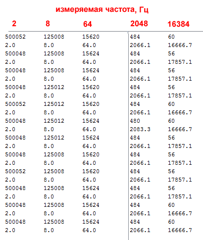
#define Tone_PIN 12 // – . #define IN_PIN 2 // volatile unsigned long ttime = 0; // volatile unsigned long time_old = 0; // volatile uint8_t flag=0; void setup() { pinMode(IR_PIN, OUTPUT); // pinMode(IN_PIN, INPUT); // attachInterrupt(0, impuls, RISING); // D2 Serial.begin(9600); // tone(Tone_PIN, 8); delay(1000); } void impuls(){ if(flag!=1) ttime =micros()-time_old; time_old = micros(); } void loop() { flag=1; // ttime Serial.println(ttime); if (ttime!=0) {// float f = 1000000/float(ttime); // Serial.println(f,1);} flag=0; delay(500); } The interrupt input here will be different - output number 2 (output PD2). As before, the flag protects against changing the ttime variable during the output process. Regarding the absence of an input frequency, the same considerations as in the previous case are valid here. The results of measuring the same frequencies are presented in the table:
As we can see, here the error in the measurements is in full accordance with the resolution of the micros () function, equal to 4 μs - that is, in fact, the result varies within plus or minus one tick of the system timer, everything is legal. This is not the best effect on the measurements of high frequencies, but for our range is quite suitable. Therefore, this method can be recommended for ordinary applications.
Measurement by the controller of the frequency generated by it
In general, this is a purely cognitive task, probably not having practical applications. But I wondered: what will happen if the measured frequency comes from the controller itself? It is convenient for this to use the tone function (), which occupies Timer2, and, therefore, will not intersect with either the system time or Timer1 if it is used for measurement. That is why in each of the sketches this function is inserted, which works through the output of Tone_PIN.
For each of the sketches, the function was uncommented, and it was first checked whether the parallel operation of the tone () function did not affect the measurements at different combinations of frequencies, both measured and generated. None of the options for explicit influence was noticed. Then the Tone_PIN pin was connected directly to the IN_PIN frequency measurement input and the port monitor was started to monitor the results.
Actually, I expected to see as a result one of two options: a) measurements will work as if nothing had happened; b) or rather, the measurements will lie shamelessly, and with a regular systematic error (which should have been due to the addition of the oscillations of two dependent timers). The reality turned out to be more interesting than the assumptions: the measurements in all three cases worked normally, but in a limited range of specified frequencies. Moreover, the lower limit was determined exactly: the input period was measured correctly, starting from 32 hertz. I did not define the upper limit precisely - it is too troublesome, but approximately it is located somewhat above 1000 Hz. Anything lower or higher is absolutely wrong. And, what is most interesting, without special regularity: the readings in the same series are the same, but after a reboot with the same given values, they become completely different.
I am not going to explain these results, but, probably, this is not very necessary. In practice, such a regime, as I have said, is useless, and if needed, it suffices to recall these empirical patterns.
Source: https://habr.com/ru/post/373213/
All Articles