We connect the "domestic" LCD 16x2 MT-16S2S by SPI. Part 2. Program
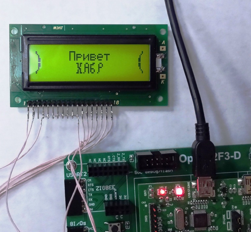
Continuing the theme of working with the indicator from the company MELT MT-16S2S on ST7070.
→ The first part.
')
In this part the main library commands will be disassembled Namely: initialization, command transfer (shift, cleaning, cursor), character output, line output, creating your character.
Here is what we got from the manufacturer:
Main: call Init16S2S clr CS mov A,#80h ;Set DDRAM address call Byte ;»_ « mov A,#3Ch ;Function set call Byte ;EXT=1 mov A,#83h ;Set data length call Byte ; 4 mov A,#'M' call Byte ;»M_ « mov A,#'E' call Byte ;»ME_ « mov A,#'L' call Byte ;»MEL_ « mov A,#'T' call Byte ;»MELT_ « mov A,#38h ;Function set call Byte ;EXT=0 mov A,#14h ;Cursor or display shift call Byte ;»MELT _ « setb CS Init16S2S
Init16S2S: clr PSB ; call Delay40ms setb SCL ; clr CS ; mov A,#38h ; Function set call Byte ;DL=1, EXT=0 mov A,#06h ; Entry mode set call Byte ; I/D=1,SH=0 mov A,#0Eh ; Display ON/OFF control call Byte ; D=1,C=1,P=0 mov A,#01h ; Clear display call Byte setb CS ; call Wait1.5ms ret Byte
Byte: mov C,ACC.7 clr SCL mov SI,C setb SCL mov C,ACC.6 clr SCL mov SI,C setb SCL mov C,ACC.5 clr SCL mov SI,C setb SCL mov C,ACC.4 clr SCL mov SI,C setb SCL mov C,ACC.3 clr SCL mov SI,C setb SCL mov C,ACC.2 clr SCL mov SI,C setb SCL mov C,ACC.1 clr SCL mov SI,C setb SCL mov C,ACC.0 clr SCL mov SI,C setb SCL Delay
Wait40us: mov A,#20 ; 12 djnz ACC,$ ret Wait1.5ms: mov R0,#38 $1: call Wait40us djnz R0,$1 ret In general, not a lot.
But the main thing - there is a sequence and description of commands. So initialization looks like this:
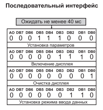
It is required to set CS to 0 and transfer 4 bytes: 38h, 0Eh, 01h, 06h. And then again set CS to 1. This is for inclusion with default options. Here you can take into account the control commands listed in the data sheet.
The first command 38h is a transition to the Function Set - Settings mode. EXT = 0, DL is not important to us, since the serial mode is set by the output of the PSB.

The second command 0Eh turns on the display and the cursor, sets the zero page of the character generator:

The third 01h clears the display. The fourth 06h translates into the Entry Mode Set mode and at the same time sets the direction of the shift to the right.

All commands after reset require 40 µs delay. Cleaning the display - 1.52 ms. Therefore, in order to eliminate flickering, it is better to fill the display with spaces instead of cleaning. Or display only the changed characters. And the cleaning command to use only when turned on. Or "menu page change" when the complete disappearance of the image is allowed. It may seem that 1.5 ms is imperceptible to the eye, but the use of the cleaning command invariably causes the image to flicker (perhaps I do not know how to use it).
In fact, initialization is just a transfer of the command to the display, so I did not make it a separate procedure. In addition, the command for setting the character generator page and turning on the cursor is transmitted along with the command for turning on the display itself. (Display ON / OF).
Created several flags to pass commands. Flags are grouped according to which of them can be transmitted simultaneously. For example, the first six one by one of a pair are transmitted in one command (Display ON / OF)
const u16 LCD_cmd_CUR_OFF = 0x8000; const u16 LCD_cmd_CUR_ON = 0x4000; const u16 LCD_cmd_DISP_OFF = 0x2000; const u16 LCD_cmd_DISP_ON = 0x1000; const u16 LCD_cmd_SetPage_0 = 0x0800; const u16 LCD_cmd_SetPage_1 = 0x0400; const u16 LCD_cmd_CUR_SHIFT = 0x200; const u16 LCD_cmd_DISP_SHIFT = 0x100; const u16 LCD_cmd_SHIFT_LEFT = 0x80; const u16 LCD_cmd_SHIFT_RIGHT = 0x40; const u16 LCD_cmd_Home = 0x0002; const u16 LCD_cmd_ClrScr = 0x0001; And then the procedure for transferring the initialization command (and this inclusion, setting the cursor, shift, etc., described in the data sheet) is as follows.
void LCD_Cmd(u16 cmd) { uint8_t toSend ; toSend = 0x8; GPIO_ResetBits(CS_Port, CS_Bit); Delay_mks(50); SPI_Send_byte(0x38); Delay_mks(50); // if ((cmd&LCD_cmd_ClrScr) >0){SPI_Send_byte(0x01);Delay_mks(50); }; // if ((cmd&LCD_cmd_Home) >0){SPI_Send_byte(0x02);Delay_mks(50); }; // if (cmd > 0x3ff){ toSend = toSend+((cmd&LCD_cmd_CUR_ON) >> 13)+ // ((cmd&LCD_cmd_DISP_ON) >> 10)+ // ((cmd&LCD_cmd_SetPage_1) >> 10); // 1 SPI_Send_byte(toSend);Delay_mks(50); }; cmd = cmd&0x3ff; toSend = 0x10; // if (cmd > 0x3f){ toSend += ((cmd&LCD_cmd_DISP_SHIFT) >> 5)+ // ((cmd&LCD_cmd_SHIFT_RIGHT) >> 4); // SPI_Send_byte(toSend); Delay_mks(50); }; SPI_Send_byte(0x38); Delay_mks(50); GPIO_SetBits(CS_Port, CS_Bit); } The command to turn on the display will look like this:
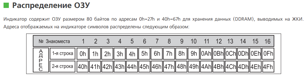
LCD_Cmd(LCD_cmd_CUR_OFF | LCD_cmd_DISP_ON | LCD_cmd_SetPage_0); The procedure for outputting a character to an arbitrary position (requires three bytes: a string, a column, a character code). The output of "its" character, when it is already recorded, is carried out by the same procedure. The sequence is as follows: the first byte (x) is the address of the position in which the character will be displayed.
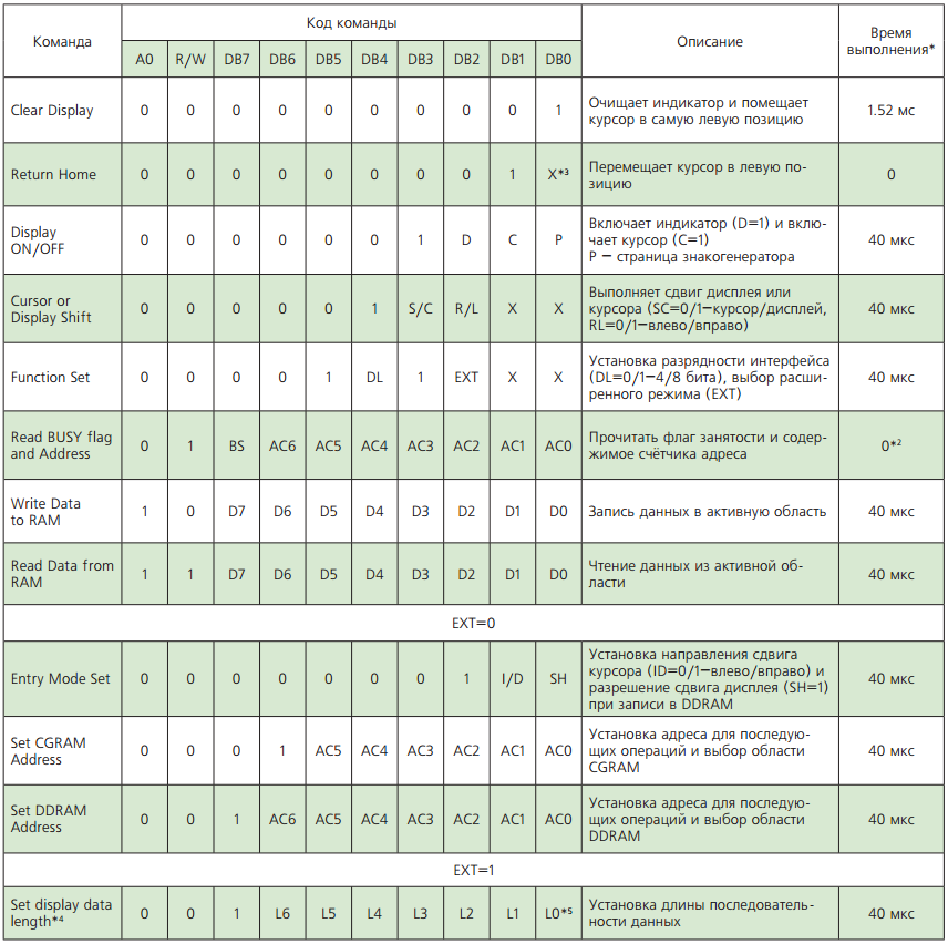
Consider the unit in the high-order address setting command.

The second byte - transition to the advanced mode (EXT = 1)
The third byte is 80h + (the number of characters is 1), in this case there is only one character, therefore 80h.
The fourth byte is the actual character code from the character generator page set above (this is where the ambush is)
Fifth - return to normal mode (EXT = 0).
void LCD_SET_PUTChar(uint8_t y,uint8_t x, char code) { x+=0x80-1+(y-1)*0x40; GPIO_ResetBits(CS_Port, CS_Bit); Delay_mks(50); SPI_Send_byte(x); Delay_mks(50); SPI_Send_byte(0x3c); Delay_mks(50); SPI_Send_byte(0x80); Delay_mks(50); SPI_Send_byte(code); Delay_mks(50); SPI_Send_byte(0x38); Delay_mks(50); GPIO_SetBits(CS_Port, CS_Bit); } The procedure for writing your character. Writes 8 bytes for a single character. While not optimal, it is worth remaking by analogy with the output of a whole line.
void LCD_SET_CustomChar(uint8_t code, const char* simbol) { uint8_t a, adr; for( j=0; j<8; j++){ adr =0x40+j+(code<<3); GPIO_ResetBits(CS_Port, CS_Bit); Delay_mks(50); SPI_Send_byte(adr); Delay_mks(50); SPI_Send_byte(0x3c); Delay_mks(50); SPI_Send_byte(0x80); Delay_mks(50); SPI_Send_byte(simbol[j]);Delay_mks(50); SPI_Send_byte(0x38); Delay_mks(50); GPIO_SetBits(CS_Port, CS_Bit); }; } Address to write from 0 to 7. As a character, an array of 8 bytes is transmitted - a graphic representation of a character. Of course, it can be obtained manually, but you can use one of the many ready-made generators. For example:

And finally, the text output. Also from the row-column position.
Also, the address of the first character, then the transition to the advanced mode, the number of bytes, the bytes themselves, return to EXT = 0.
void LCD_print_text (uint8_t y, uint8_t x, char * text)
{
u8 nBytes;
if (! text) return;
nBytes = strlen (text);
if (nBytes> 80) return;
x + = 0x80-1 + (y-1) * 0x40;
GPIO_ResetBits (CS_Port, CS_Bit); Delay_mks (50);
SPI_Send_byte (x); Delay_mks (50);
SPI_Send_byte (0x3c); Delay_mks (50);
SPI_Send_byte (0x80 + nBytes-1); Delay_mks (50);
for (j = 0; j <nBytes; j ++) {
SPI_Send_byte (text [j]); Delay_mks (50); };
SPI_Send_byte (0x38); Delay_mks (50);
GPIO_SetBits (CS_Port, CS_Bit);
}
The code is written in Keil for STM32. The default setting for the periphery for ARM controllers.
PS And I am not a real welder, I have found a book on programming on the Internet ...
Source: https://habr.com/ru/post/373141/
All Articles