Radar Antenna Guide
An article for translation is proposed by alessandro893 . The material is taken from an extensive reference site, describing, in particular, the principles of operation and the construction of radars.
An antenna is an electrical device that converts electricity into radio waves and vice versa. The antenna is used not only in radars, but also in jammers, radiation warning systems and communications systems. When transmitting, the antenna concentrates the energy of the radar transmitter and forms a beam directed in the right direction. When receiving the antenna collects the returning energy of the radar contained in the reflected signals, and transmits them to the receiver. Antennas often differ in beam shape and efficiency.
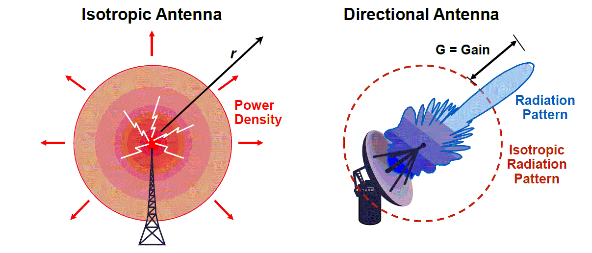
Left - isotropic antenna, right - directional
')
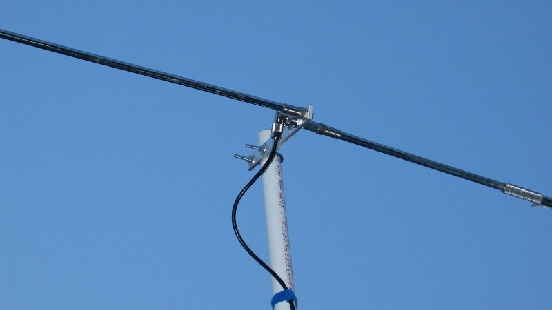
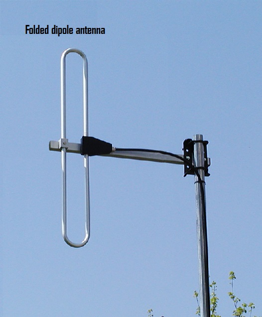
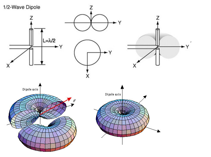
A dipole antenna, or dipole, is the simplest and most popular class of antennas. Consists of two identical conductors, wires or rods, usually with two-sided symmetry. For transmitting devices, current is supplied to it, and for receiving devices, a signal is received between the two halves of the antenna. Both sides of the feeder at the transmitter or receiver are connected to one of the conductors. Dipoles are resonating antennas, that is, their elements serve as resonators in which standing waves travel from one end to the other. So the length of the elements of the dipole is determined by the length of the radio wave.
Dipoli are omnidirectional antennas. In this regard, they are often used in communication systems.
The unbalanced antenna is half dipole, and is mounted perpendicular to the conductive surface, a horizontal reflecting element. The coefficient of directional action of a monopole antenna is twice as large as that of a double-dipole antenna, since there is no radiation under the horizontal reflecting element. In this regard, the directivity factor of such an antenna is twice as high, and it is capable of transmitting waves further using the same transmit power.

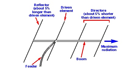
Yagi antenna - a directional antenna, consisting of several parallel elements located on the same line. Often consist of a single irradiator element, usually a dipole or loop vibrator. Only this element experiences excitement. The remaining elements are parasitic - they reflect or help to transfer energy in the right direction. The irradiator (active vibrator) is usually located second from the end, as in the image below. Its size is chosen in order to achieve resonance in the presence of parasitic elements (for a dipole, this is usually 0.45 - 0.48 of the wavelength). The element to the left of the irradiator is a reflector (reflector). It is usually longer than the feed. The reflector is usually one, since the addition of additional reflectors has little effect on efficiency. It affects the power ratio of the antenna signals emitted in the backward / forward directions (gain in the maximum direction relative to the opposite). To the right of the irradiator are the elements-directors, which are usually shorter than the irradiator. The Yagi antenna has a very narrow operating frequency range, and the maximum gain is approximately 17 dB.
Type of antenna often used on VHF and UHF transmitters. It consists of an irradiator (it can be a dipole or Yagi massif), reinforced in front of two flat rectangular reflecting screens connected at an angle, usually at 90 °. The reflector can be a sheet of metal or a grid (for low-frequency radars), reducing weight and reducing wind resistance. The corner antennas have a wide range, and the gain is about 10-15 dB.
A log-periodic antenna (LPA) consists of several half-wave dipole emitters of gradually increasing length. Each consists of a pair of metal rods. Dipoles are attached closely, one after the other, and are connected to the feeder in parallel, with opposite phases. This antenna looks like a Yagi antenna, but it works differently. Adding elements to the Yagi antenna increases its directivity (gain), and adding elements to the LPA increases its frequency band. Its main advantage over other antennas is an extremely wide range of operating frequencies. The lengths of the antenna elements refer to each other according to a logarithmic law. The length of the longest of the elements is 1/2 of the wavelength of the lowest frequency, and the shortest is 1/2 of the wavelength of the highest frequency.

Spiral antenna consists of a conductor twisted into a spiral. They are usually mounted above a horizontal reflective element. The feeder connects to the bottom of the spiral and the horizontal plane. They can operate in two modes - normal and axial.
Normal (transverse) mode: the dimensions of the spiral (diameter and slope) are small compared to the wavelength of the transmitted frequency. The antenna works in the same way as a short-circuited dipole or monopole, with the same radiation pattern. The radiation is linearly polarized parallel to the axis of the helix. This mode is used in compact antennas for portable and mobile radios.
Axial mode: the dimensions of the spiral are comparable with the wavelength. The antenna works as a direction, transmitting the beam from the end of the helix along its axis. Radiates radio waves of circular polarization. Often used for satellite communications.


A rhombic antenna is a broadband directional antenna consisting of one to three parallel wires fixed above the ground in the form of a rhomb supported at each apex by towers or poles to which the wires are attached with insulators. All four sides of an antenna are the same length, usually at least one wavelength, or longer. Often used to communicate and work in the range of decameter waves.
Multi-element array of dipoles used in the HF bands (1.6 - 30 MHz), consisting of rows and columns of dipoles. The number of rows can be 1, 2, 3, 4 or 6. The number of columns is 2 or 4. The dipoles are horizontally polarized, and the reflecting screen is located behind the array of dipoles to provide an amplified beam. The number of columns of dipoles determines the width of the azimuth beam. For 2 columns, the width of the radiation pattern is about 50 °, for 4 columns - 30 °. The main beam can be deflected by 15 ° or 30 ° to obtain a maximum coverage of 90 °.
The number of rows and the height of the lowest element above the ground determines the elevation angle and the size of the territory served. An array of two rows has an angle of 20 °, and of four - at 10 °. The radiation of a two-dimensional lattice usually approaches the ionosphere at a small angle, and due to the low frequency is often reflected back to the surface of the earth. Since radiation can be repeatedly reflected between the ionosphere and the earth, the antenna is not limited to the horizon. As a result, such an antenna is often used for long distance communication.
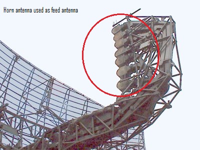
A horn antenna consists of an expanding metal waveguide in the shape of a horn that collects radio waves into a beam. Horn antennas have a very wide operating frequency range, they can operate with a 20-fold rupture of its borders - for example, from 1 to 20 GHz. Gain varies from 10 to 25 dB, and they are often used as feeds for larger antennas.

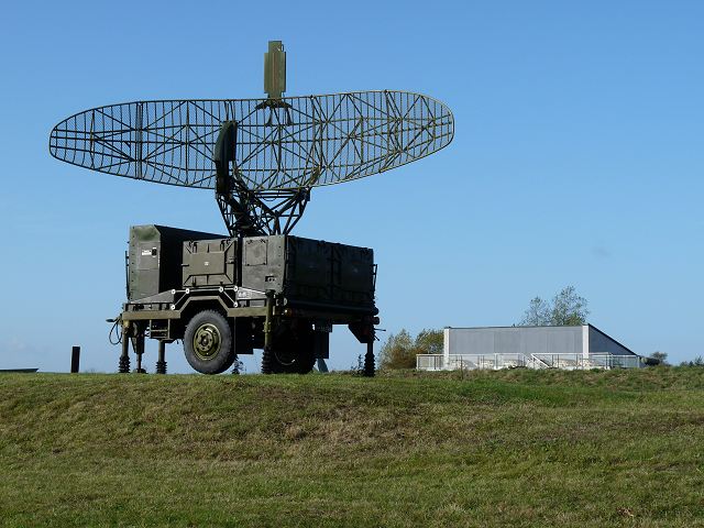
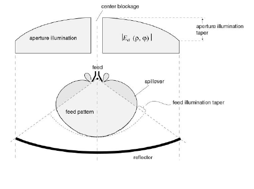
One of the most popular radar antennas is a parabolic reflector. The irradiator is located at the focus of the parabola, and the radar energy is directed to the surface of the reflector. Most often a horn antenna is used as an irradiator, but it is possible to use both a dipole and a helical antenna.

Since the point source of energy is in focus, it is transformed into a wave front of the constant phase, which makes the parabola well adapted for use in radars. By changing the size and shape of the reflecting surface, you can create rays and radiation patterns of various shapes. The directivity of parabolic antennas is much better than that of Yagi or dipole, the gain can reach 30-35 dB. Their main drawback - the inability to low frequencies because of the size. Another one - the feed can block part of the signal.

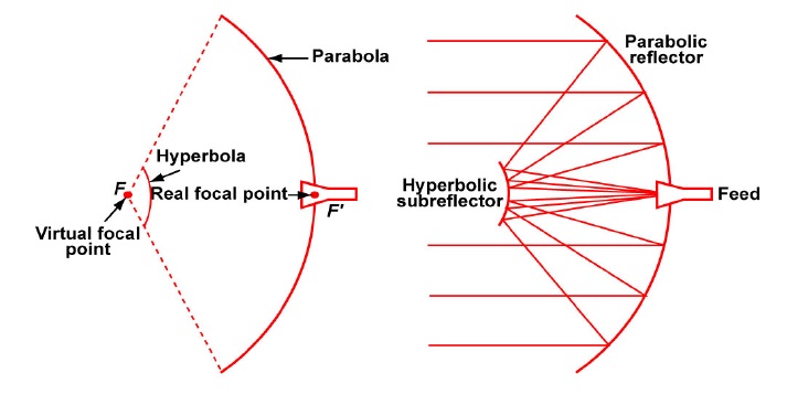
The Cassegrain antenna is very similar to the usual parabolic, but uses a system of two reflectors to create and focus the radar beam. The main reflector is parabolic, and the auxiliary reflector is hyperbolic. The irradiator is in one of the two foci of hyperbole. Radar energy from the transmitter is reflected from the auxiliary reflector on the main one and focuses. The energy returning from the target is collected by the main reflector and is reflected in the form of a beam converging at one point to an auxiliary one. It is then reflected by the auxiliary reflector and assembled at the point where the feed is located. The larger the auxiliary reflector, the closer it can be to the main one. This design reduces the axial dimensions of the radar, but increases the shading of the aperture. A small auxiliary reflector, on the contrary, reduces the shading of the aperture, but it should be located away from the main one. Advantages over a parabolic antenna: compactness (despite the presence of a second reflector, the total distance between two reflectors is less than the distance from the irradiator to the parabolic antenna reflector), loss reduction (the receiver can be placed close to the horn radiator), reduction of side-lobe interference for ground radar. Main disadvantages: the beam is blocked more strongly (the size of the auxiliary reflector and the irradiator is larger than the size of the irradiator of a conventional parabolic antenna), does not work well with a wide range of waves.


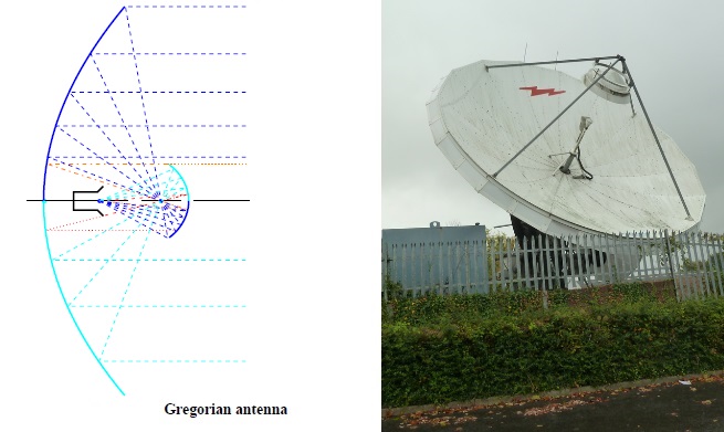
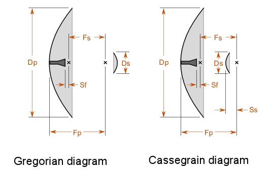
On the left is Gregory's antenna, on the right - Cassegrain
Gregory's parabolic antenna is very similar in structure to the Cassegrain antenna. The difference is that the auxiliary reflector is bent in the opposite direction. Gregory's design may use a smaller auxiliary reflector compared to a Cassegrain antenna, as a result of which a smaller part of the beam is blocked.
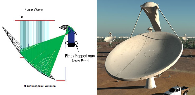

As the name implies, the emitter and the auxiliary reflector (if it is a Gregory antenna) of the offset antenna are offset from the center of the main reflector so as not to block the beam. Such a scheme is often used on parabolic antennas and Gregory antennas to increase efficiency.
Another scheme designed to combat beam blocking with an auxiliary reflector is a flat-plate Cassegrain antenna. It works taking into account the polarization of the waves. An electromagnetic wave has 2 components, magnetic and electric, always located perpendicular to each other and the direction of motion. The polarization of the wave is determined by the orientation of the electric field, it is linear (vertical / horizontal) or circular (circular or elliptical, twisted clockwise or counterclockwise). The most interesting thing in polarization is the polarizer, or the process of filtering waves, leaving only waves polarized in one direction or in one plane. Usually a polarizer is made of a material with a parallel arrangement of atoms, or it can be a grid of parallel wires, the distance between which is less than the wavelength. It is often assumed that the distance should be about half the wavelength.
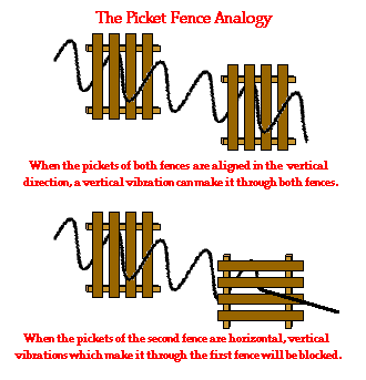
A common misconception is that an electromagnetic wave and a polarizer work in a similar way with an oscillating cable and a wooden fence — that is, for example, a horizontally polarized wave should be blocked by a screen with vertical slits.
In fact, electromagnetic waves do not behave like mechanical ones. The grid of parallel horizontal wires completely blocks and reflects the horizontally polarized radio wave and transmits the vertically polarized - and per revolution. The reason is as follows: when the electric field, or wave, is parallel to the wire, they excite electrons along the length of the wire, and since the length of the wire exceeds its thickness many times, the electrons can move easily and absorb most of the wave energy. The movement of electrons will lead to the appearance of a current, and the current will create its own waves. These waves will dampen the transmission waves and will behave as reflected. On the other hand, when the electric field of the wave is perpendicular to the wires, it will excite electrons along the width of the wire. Since the electrons cannot actively move in this way, a very small part of the energy will be reflected.

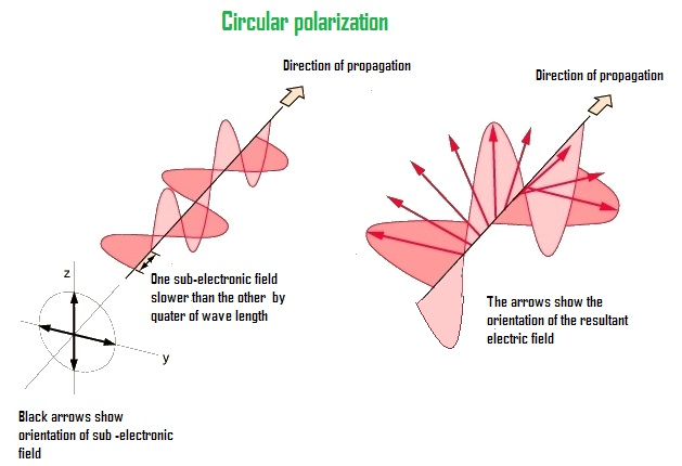
It is important to note that, although in most of the illustrations, radio waves have only 1 magnetic and 1 electric field, this does not mean that they oscillate strictly in one plane. In fact, it is possible to imagine that electric and magnetic fields consist of several subfields that are folded vector. For example, in a vertically polarized wave from two subfields, the result of the addition of their vectors is vertical. When two subfields coincide in phase, the resulting electric field will always be stationary in the same plane. But if one of the subfields is slower than the other, then the resulting field will begin to rotate around the direction of the wave (this is often called elliptical polarization). If one subfield is slower than the others by exactly a quarter of the wavelength (the phase differs by 90 degrees), then we get circular polarization:
To convert a linear polarization of a wave into a circular polarization and back it is necessary to slow down one of the subfields relative to the others by exactly a quarter of the wavelength. For this, the lattice is most often used (a quarter-wave phase plate ) made of parallel wires with a 1/4 wavelength between them located at an angle of 45 degrees to the horizontal.
In a wave passing through a device, linear polarization turns into circular, and circular - into linear.

The Cassegrain antenna operating on this principle with a flat phase plate consists of two reflectors of equal size. Auxiliary reflects only waves with horizontal polarization and transmits waves with vertical polarization. The main reflects all the waves. Plate auxiliary reflector is located in front of the main. It consists of two parts - a plate with slots running at an angle of 45 °, and a plate with horizontal slots of width less than 1/4 of the wavelength.

Suppose an irradiator transmits a wave with circular polarization counterclockwise. The wave passes through a quarter-wave plate and turns into a wave with horizontal polarization. It is reflected from horizontal wires. Again, it passes through a quarter-wave plate, on the other hand, and for it the wires of the plate are already oriented mirror-like, that is, as if turned by 90 °. The previous polarization reversal is canceled, so that the wave again acquires circular polarization counterclockwise and travels back to the main reflector. The reflector changes polarization from going counterclockwise to going clockwise. It passes through the horizontal slots of the auxiliary reflector without resistance and goes in the direction of the targets vertically polarized. In reception mode, everything happens the other way around.
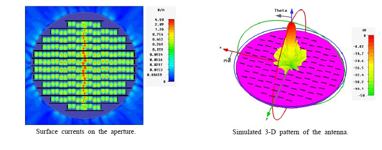
Although the described antennas have a rather large gain with respect to the size of the aperture, all of them have common drawbacks: large side lobe susceptibility (susceptibility to interfering reflections from the earth's surface and sensitivity to targets with a low scattering area), a decrease in efficiency due to beam blocking (the problem with blocking is in small radars that can be used on flying vehicles; large radars, where the problem with blocking is less, cannot be used in the air). As a result, a new antenna scheme was invented - a slit. It is made in the form of a metal surface, usually flat, in which holes or slots are cut. When it is irradiated at the desired frequency, electromagnetic waves are emitted from each slot - that is, the slots act as separate antennas and form an array. Since the beam from each slot is weak, their side lobes are also very small. Slot antennas are characterized by high gain, small side lobes and low weight. They may be missing protruding parts, which in some cases is their important advantage (for example, when installed on aircraft).


Radar with MiG-31
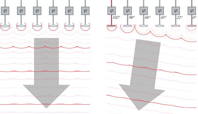
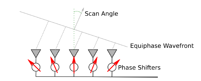
From the early days of creating radar developers, there was one problem: the balance between accuracy, range and radar scan time. It arises from the fact that radars with a narrower beam width increase accuracy (resolution increases) and range at the same power (power concentration). But the smaller the beam width, the longer the radar scans the entire field of view. Moreover, a high gain radar will require larger antennas, which is inconvenient for fast scanning. To achieve practical accuracy at low frequencies, radar would require such huge antennas that it would be difficult to turn them from a mechanical point of view. To solve this problem, a passive phased array antenna was created. It relies not on the mechanics, but on the interference of the waves to control the beam.If two or more waves of the same type oscillate and meet at one point in space, the total amplitude of the waves is added up in about the same way as the waves on the water. Depending on the phases of these waves, interference can strengthen or weaken them.
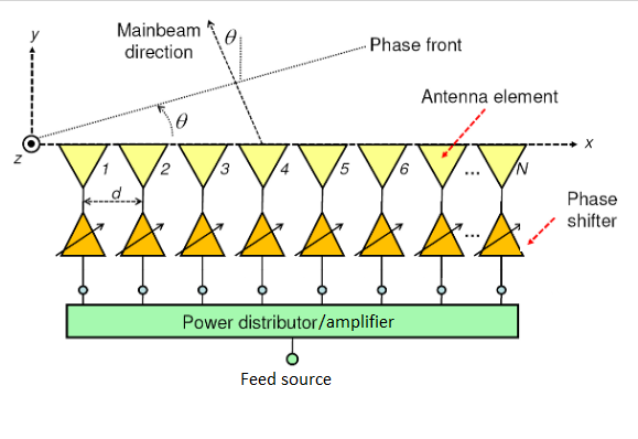
The beam can be formed and controlled electronically, controlling the phase difference of the group of transmitting elements — in this way, it can be controlled in what places the amplifying or weakening interference occurs. From this it follows that in the aircraft radar to control the beam from side to side there must be at least two transmitting elements.

Usually a radar with PFAR consists of 1 irradiator, one LNA (low-noise amplifier), one power distributor, 1000-2000 transmitting elements and an equal number of phase shifters.
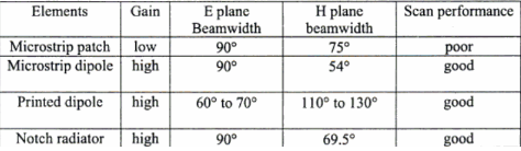
Transmitting elements can be isotropic or directional antennas. Some typical types of transmitting elements:
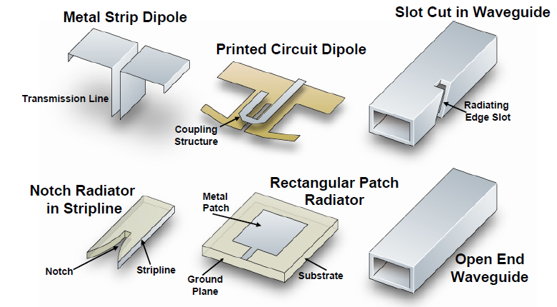
In the first generations of fighters, patch antennas (strip antennas) were most often used , since they are the easiest to develop.
Modern active-phase arrays use flute emitters due to their broadband capabilities and improved gain:

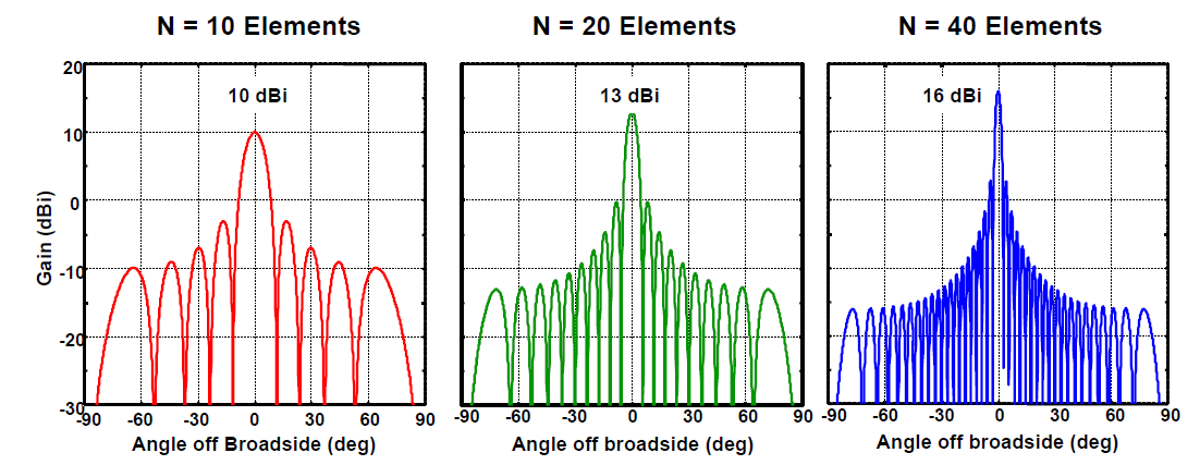
Regardless of the type of antenna used, increasing the number of radiating elements improves the radar's directional characteristics.
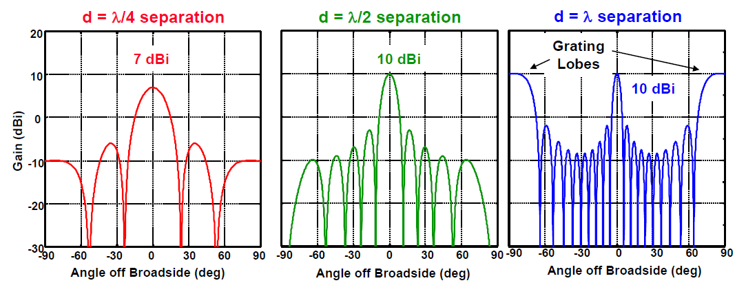
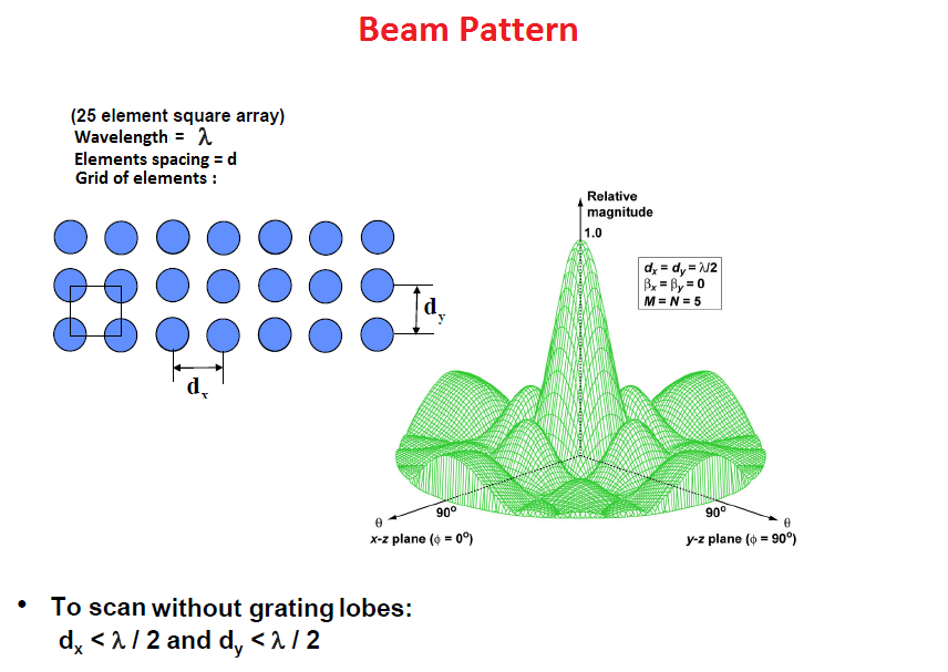
As we know, with the same radar frequency, an increase in the aperture leads to a decrease in the beam width, which increases the range and accuracy. But with phased arrays it is not worth increasing the distance between the radiating elements in an attempt to increase the aperture and reduce the cost of the radar. Because if the distance between the elements is greater than the operating frequency, side lobes may appear, significantly reducing the effectiveness of the radar.
The most important and expensive part of the PPAR is phase shifters. Without them, it is impossible to control the phase of the signal and the direction of the beam.
They are of different types, but in general they can be divided into four types.

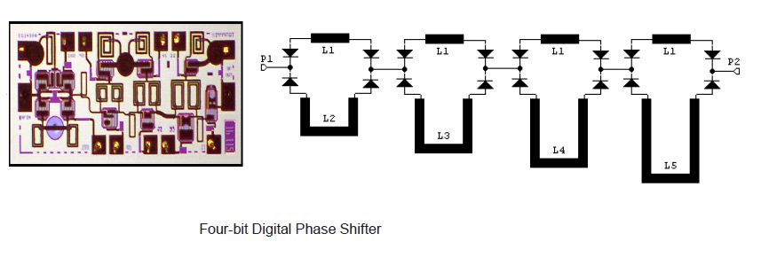
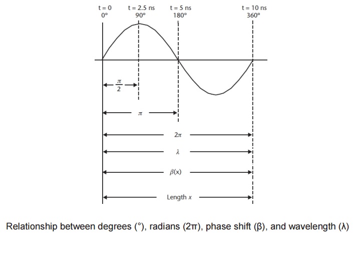
The simplest type of phase shifters. The signal for passing the transmission line takes time. This delay, equal to the phase shift of the signal, depends on the length of the transmission line, the frequency of the signal and the phase velocity of the signal in the transmitting material. By switching the signal between two or more transmission lines of a given length, you can control the phase shift. Switching elements are mechanical relays, pin diodes, field-effect transistors or microelectromechanical systems. Pin diodes are often used due to high speed, low losses and simple bias circuits, providing resistance changes from 10 kΩ to 1 Ω.
Delay, sec = phase shift ° / (360 * frequency, Hz)
Their disadvantage is an increase in phase error with an increase in frequency and an increase in size with a decrease in frequency. Also, the phase change varies depending on the frequency, so they are not applicable for too low and high frequencies.
Usually this is a quadrature communication device that divides the input signal into two signals that differ in phase by 90 °, which are then reflected. They are then combined in phase at the outlet. This scheme works due to the fact that the reflection of the signal from the conductive lines can be shifted in phase with respect to the falling signal. The phase shift varies from 0 ° (open circuit, zero capacity of the varactor ) to -180 ° (circuit is short-circuited, the capacity of the varactor is infinite). Such phase shifters have a wide range of work. However, the physical limitations of varactors lead to the fact that, in practice, the phase shift can only reach 160 °. But for a greater shift it is possible to combine several such chains.
As with the reflective phase shifter, the signal is divided into two outputs with a 90-degree phase shift. The incoming phase without offset is called the I-channel, and the quadrature with the 90-degree offset is called the Q-channel. Each signal then passes through a two-phase modulator capable of shifting the phase of the signal. Each signal is subject to a phase shift of 0 ° or 180 °, which allows you to select any pair of quadrature vectors. Then the two signals are recombined. Since the attenuation of both signals can be controlled, the output signal controls not only the phase, but also the amplitude.

It was made to solve the problem of phase shifters with a time delay, not capable of operating at a large frequency range. Works by switching the signal path between the high and low pass filters. It looks like a phase shifter with a time delay, only filters are used instead of transmission lines. A high pass filter consists of a series of inductors and capacitors that provide phase advance. This phase shifter provides a constant phase shift in the operating frequency range. Also, its size is much smaller than the previous phase shifters listed, so it is most often used in radars.
To sum up, compared to a conventional reflecting antenna, the main advantages of PPAR will be: high scanning speed (increasing the number of monitored targets, reducing the likelihood of detection by the radiation warning station), optimizing the target time, high gain and small side lobes (it is harder to silence and detect), random scan sequence (harder to drown out), the ability to use special modulation and detection techniques to extract the signal from the noise. The main disadvantages are high cost, the impossibility of scanning wider than 60 degrees wide (the field of view of a stationary phase array is 120 degrees, mechanical radar can expand it to 360).


Outside AFAR (AESA) and PFAR (PESA) is difficult to distinguish, but inside they are radically different. PFAR uses one or two high-power amplifiers that transmit one signal, which is then divided into thousands of paths for thousands of phase shifters and elements. Radar with AFAR consists of thousands of modules of reception / transmission. Since the transmitters are located directly in the elements themselves, it does not have a separate receiver and transmitter. The differences in architecture are shown in the picture.
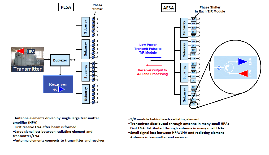
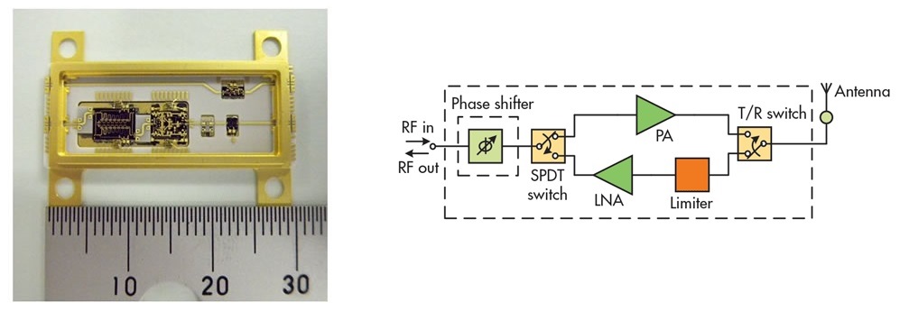
In AFAR, most of the components, such as a weak signal amplifier, a high power amplifier, a duplexer, a phase shifter, are reduced and assembled in a single package called a receive / transmit module. Each of the modules is a small radar. Their architecture is as follows:

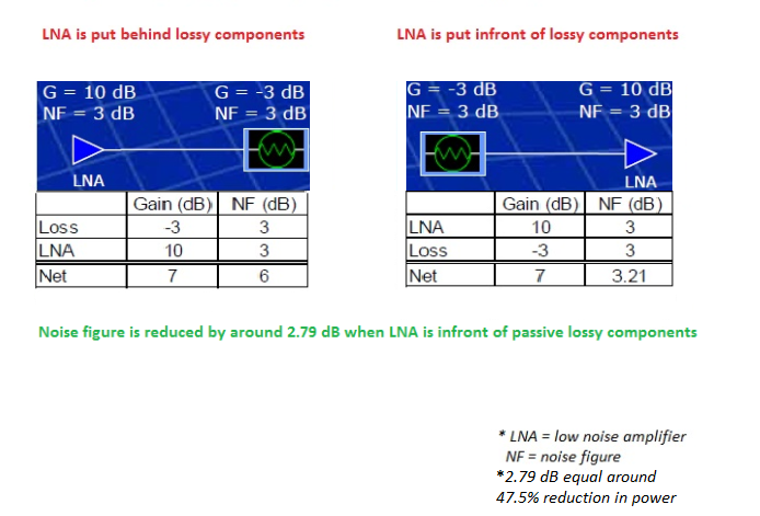
Although AFAR (AESA) and PFAR (PESA) use wave interference to form and deflect a beam, the unique design of AFAR provides many advantages over PFAR. For example, a weak signal amplifier is located next to the receiver, to the components where part of the signal is lost, so its signal-to-noise ratio is better than that of PPAR.

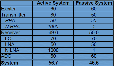
Secondly, in conventional radar, the possibility of reducing parasitic interference is limited by the errors of the instability of the equipment. Most of these errors are contributed by an analog-to-digital converter, a down-converter, high-power amplifiers, weak signal amplifiers, and a wave generator. In AFAR with a distributed group of high power amplifiers and weak signal amplifiers, such errors can be reduced. As a result, AFAR increases sensitivity in noisy environments.
Moreover, with equal detection capabilities, AFAR has less duty cycle and peak power. Also, since individual AFAR modules do not rely on a single amplifier, they can simultaneously transmit signals with different frequencies. As a result, AFAR can create several separate rays, dividing the array into sub-arrays. The ability to work on multiple frequencies brings multitasking and the ability to deploy electronic jamming systems anywhere relative to the radar. But the formation of too many simultaneous rays reduces the range of the radar.

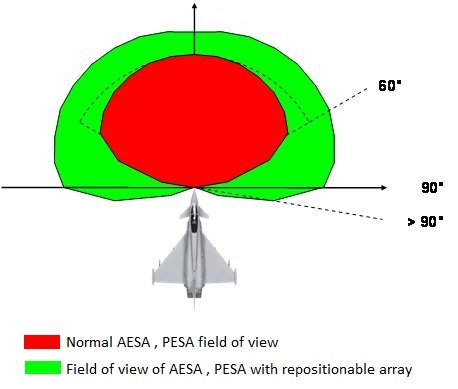
The two main disadvantages of AFAR are the high cost and the limited field of view of 60 degrees.
Hybrid Electromechanical Phased Antenna Arrays


A very high speed scanning of the PAR is combined with a limited field of view. To solve this problem, modern radars are located on a movable disk, which increases the field of view. Do not confuse the field of view with the width of the beam. The beam width refers to the radar beam, and the field of view is the total size of the scanned space. Narrow beams are often needed to improve accuracy and range, and a narrow field of view is usually not needed.
An antenna is an electrical device that converts electricity into radio waves and vice versa. The antenna is used not only in radars, but also in jammers, radiation warning systems and communications systems. When transmitting, the antenna concentrates the energy of the radar transmitter and forms a beam directed in the right direction. When receiving the antenna collects the returning energy of the radar contained in the reflected signals, and transmits them to the receiver. Antennas often differ in beam shape and efficiency.
Left - isotropic antenna, right - directional
')
Dipole antenna
A dipole antenna, or dipole, is the simplest and most popular class of antennas. Consists of two identical conductors, wires or rods, usually with two-sided symmetry. For transmitting devices, current is supplied to it, and for receiving devices, a signal is received between the two halves of the antenna. Both sides of the feeder at the transmitter or receiver are connected to one of the conductors. Dipoles are resonating antennas, that is, their elements serve as resonators in which standing waves travel from one end to the other. So the length of the elements of the dipole is determined by the length of the radio wave.
Directional pattern
Dipoli are omnidirectional antennas. In this regard, they are often used in communication systems.
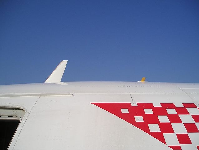
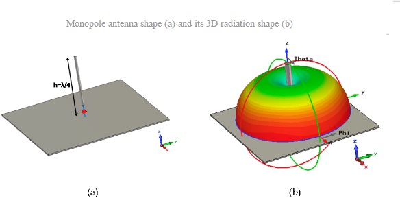
Antenna in the form of asymmetric vibrator (monopoly)
The unbalanced antenna is half dipole, and is mounted perpendicular to the conductive surface, a horizontal reflecting element. The coefficient of directional action of a monopole antenna is twice as large as that of a double-dipole antenna, since there is no radiation under the horizontal reflecting element. In this regard, the directivity factor of such an antenna is twice as high, and it is capable of transmitting waves further using the same transmit power.
Directional pattern
Wave channel antenna, Yagi-Oud antenna, Yagi antenna
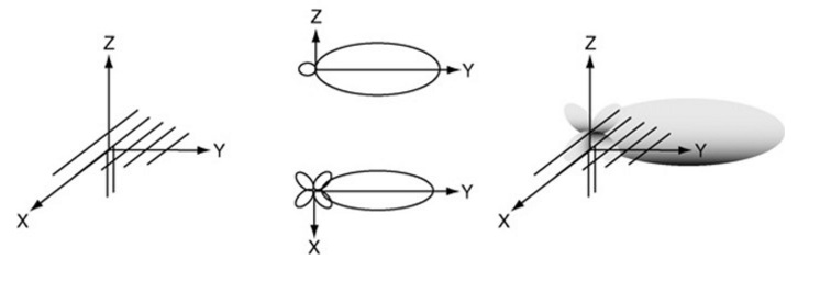
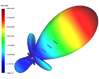
Yagi antenna - a directional antenna, consisting of several parallel elements located on the same line. Often consist of a single irradiator element, usually a dipole or loop vibrator. Only this element experiences excitement. The remaining elements are parasitic - they reflect or help to transfer energy in the right direction. The irradiator (active vibrator) is usually located second from the end, as in the image below. Its size is chosen in order to achieve resonance in the presence of parasitic elements (for a dipole, this is usually 0.45 - 0.48 of the wavelength). The element to the left of the irradiator is a reflector (reflector). It is usually longer than the feed. The reflector is usually one, since the addition of additional reflectors has little effect on efficiency. It affects the power ratio of the antenna signals emitted in the backward / forward directions (gain in the maximum direction relative to the opposite). To the right of the irradiator are the elements-directors, which are usually shorter than the irradiator. The Yagi antenna has a very narrow operating frequency range, and the maximum gain is approximately 17 dB.
Directional pattern
Corner antenna
Type of antenna often used on VHF and UHF transmitters. It consists of an irradiator (it can be a dipole or Yagi massif), reinforced in front of two flat rectangular reflecting screens connected at an angle, usually at 90 °. The reflector can be a sheet of metal or a grid (for low-frequency radars), reducing weight and reducing wind resistance. The corner antennas have a wide range, and the gain is about 10-15 dB.
Directional pattern
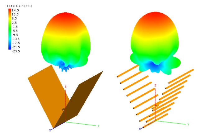
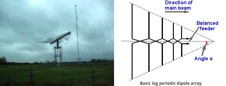
Vibratory log-periodic (log-periodic) antenna, or a log-periodic array of symmetrical vibrators
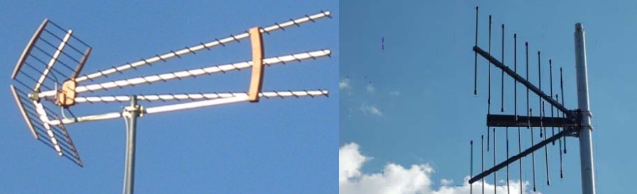
A log-periodic antenna (LPA) consists of several half-wave dipole emitters of gradually increasing length. Each consists of a pair of metal rods. Dipoles are attached closely, one after the other, and are connected to the feeder in parallel, with opposite phases. This antenna looks like a Yagi antenna, but it works differently. Adding elements to the Yagi antenna increases its directivity (gain), and adding elements to the LPA increases its frequency band. Its main advantage over other antennas is an extremely wide range of operating frequencies. The lengths of the antenna elements refer to each other according to a logarithmic law. The length of the longest of the elements is 1/2 of the wavelength of the lowest frequency, and the shortest is 1/2 of the wavelength of the highest frequency.
Directional pattern
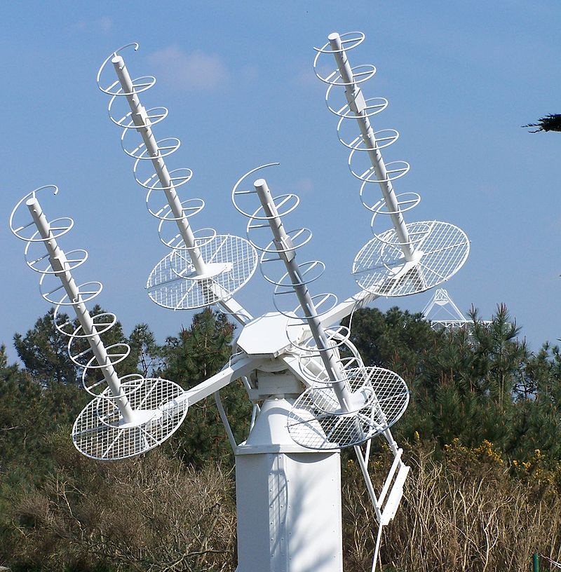
Spiral antenna
Spiral antenna consists of a conductor twisted into a spiral. They are usually mounted above a horizontal reflective element. The feeder connects to the bottom of the spiral and the horizontal plane. They can operate in two modes - normal and axial.
Normal (transverse) mode: the dimensions of the spiral (diameter and slope) are small compared to the wavelength of the transmitted frequency. The antenna works in the same way as a short-circuited dipole or monopole, with the same radiation pattern. The radiation is linearly polarized parallel to the axis of the helix. This mode is used in compact antennas for portable and mobile radios.
Axial mode: the dimensions of the spiral are comparable with the wavelength. The antenna works as a direction, transmitting the beam from the end of the helix along its axis. Radiates radio waves of circular polarization. Often used for satellite communications.
Directional pattern
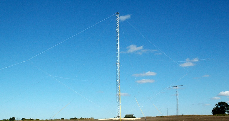
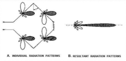
Rhombic antenna
A rhombic antenna is a broadband directional antenna consisting of one to three parallel wires fixed above the ground in the form of a rhomb supported at each apex by towers or poles to which the wires are attached with insulators. All four sides of an antenna are the same length, usually at least one wavelength, or longer. Often used to communicate and work in the range of decameter waves.
Directional pattern
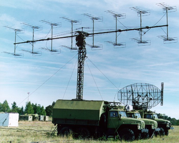
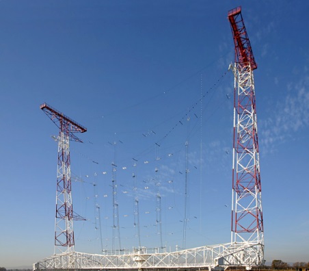
2D antenna array
Multi-element array of dipoles used in the HF bands (1.6 - 30 MHz), consisting of rows and columns of dipoles. The number of rows can be 1, 2, 3, 4 or 6. The number of columns is 2 or 4. The dipoles are horizontally polarized, and the reflecting screen is located behind the array of dipoles to provide an amplified beam. The number of columns of dipoles determines the width of the azimuth beam. For 2 columns, the width of the radiation pattern is about 50 °, for 4 columns - 30 °. The main beam can be deflected by 15 ° or 30 ° to obtain a maximum coverage of 90 °.
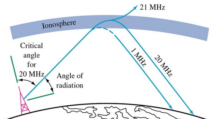
The number of rows and the height of the lowest element above the ground determines the elevation angle and the size of the territory served. An array of two rows has an angle of 20 °, and of four - at 10 °. The radiation of a two-dimensional lattice usually approaches the ionosphere at a small angle, and due to the low frequency is often reflected back to the surface of the earth. Since radiation can be repeatedly reflected between the ionosphere and the earth, the antenna is not limited to the horizon. As a result, such an antenna is often used for long distance communication.
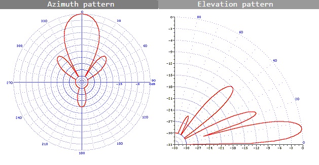
Directional pattern
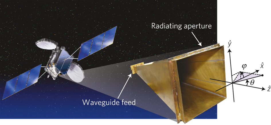
Horn antenna
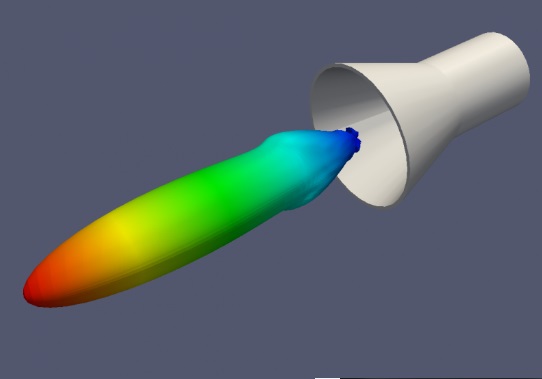
A horn antenna consists of an expanding metal waveguide in the shape of a horn that collects radio waves into a beam. Horn antennas have a very wide operating frequency range, they can operate with a 20-fold rupture of its borders - for example, from 1 to 20 GHz. Gain varies from 10 to 25 dB, and they are often used as feeds for larger antennas.
Directional pattern
Parabolic antenna
One of the most popular radar antennas is a parabolic reflector. The irradiator is located at the focus of the parabola, and the radar energy is directed to the surface of the reflector. Most often a horn antenna is used as an irradiator, but it is possible to use both a dipole and a helical antenna.
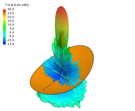
Since the point source of energy is in focus, it is transformed into a wave front of the constant phase, which makes the parabola well adapted for use in radars. By changing the size and shape of the reflecting surface, you can create rays and radiation patterns of various shapes. The directivity of parabolic antennas is much better than that of Yagi or dipole, the gain can reach 30-35 dB. Their main drawback - the inability to low frequencies because of the size. Another one - the feed can block part of the signal.
Directional pattern
Cassegren's antenna
The Cassegrain antenna is very similar to the usual parabolic, but uses a system of two reflectors to create and focus the radar beam. The main reflector is parabolic, and the auxiliary reflector is hyperbolic. The irradiator is in one of the two foci of hyperbole. Radar energy from the transmitter is reflected from the auxiliary reflector on the main one and focuses. The energy returning from the target is collected by the main reflector and is reflected in the form of a beam converging at one point to an auxiliary one. It is then reflected by the auxiliary reflector and assembled at the point where the feed is located. The larger the auxiliary reflector, the closer it can be to the main one. This design reduces the axial dimensions of the radar, but increases the shading of the aperture. A small auxiliary reflector, on the contrary, reduces the shading of the aperture, but it should be located away from the main one. Advantages over a parabolic antenna: compactness (despite the presence of a second reflector, the total distance between two reflectors is less than the distance from the irradiator to the parabolic antenna reflector), loss reduction (the receiver can be placed close to the horn radiator), reduction of side-lobe interference for ground radar. Main disadvantages: the beam is blocked more strongly (the size of the auxiliary reflector and the irradiator is larger than the size of the irradiator of a conventional parabolic antenna), does not work well with a wide range of waves.
Directional pattern
Gregory aerial
On the left is Gregory's antenna, on the right - Cassegrain
Gregory's parabolic antenna is very similar in structure to the Cassegrain antenna. The difference is that the auxiliary reflector is bent in the opposite direction. Gregory's design may use a smaller auxiliary reflector compared to a Cassegrain antenna, as a result of which a smaller part of the beam is blocked.
Offset (asymmetric) antenna
As the name implies, the emitter and the auxiliary reflector (if it is a Gregory antenna) of the offset antenna are offset from the center of the main reflector so as not to block the beam. Such a scheme is often used on parabolic antennas and Gregory antennas to increase efficiency.
Cassegrain antenna with a flat phase plate
Another scheme designed to combat beam blocking with an auxiliary reflector is a flat-plate Cassegrain antenna. It works taking into account the polarization of the waves. An electromagnetic wave has 2 components, magnetic and electric, always located perpendicular to each other and the direction of motion. The polarization of the wave is determined by the orientation of the electric field, it is linear (vertical / horizontal) or circular (circular or elliptical, twisted clockwise or counterclockwise). The most interesting thing in polarization is the polarizer, or the process of filtering waves, leaving only waves polarized in one direction or in one plane. Usually a polarizer is made of a material with a parallel arrangement of atoms, or it can be a grid of parallel wires, the distance between which is less than the wavelength. It is often assumed that the distance should be about half the wavelength.
A common misconception is that an electromagnetic wave and a polarizer work in a similar way with an oscillating cable and a wooden fence — that is, for example, a horizontally polarized wave should be blocked by a screen with vertical slits.
In fact, electromagnetic waves do not behave like mechanical ones. The grid of parallel horizontal wires completely blocks and reflects the horizontally polarized radio wave and transmits the vertically polarized - and per revolution. The reason is as follows: when the electric field, or wave, is parallel to the wire, they excite electrons along the length of the wire, and since the length of the wire exceeds its thickness many times, the electrons can move easily and absorb most of the wave energy. The movement of electrons will lead to the appearance of a current, and the current will create its own waves. These waves will dampen the transmission waves and will behave as reflected. On the other hand, when the electric field of the wave is perpendicular to the wires, it will excite electrons along the width of the wire. Since the electrons cannot actively move in this way, a very small part of the energy will be reflected.
It is important to note that, although in most of the illustrations, radio waves have only 1 magnetic and 1 electric field, this does not mean that they oscillate strictly in one plane. In fact, it is possible to imagine that electric and magnetic fields consist of several subfields that are folded vector. For example, in a vertically polarized wave from two subfields, the result of the addition of their vectors is vertical. When two subfields coincide in phase, the resulting electric field will always be stationary in the same plane. But if one of the subfields is slower than the other, then the resulting field will begin to rotate around the direction of the wave (this is often called elliptical polarization). If one subfield is slower than the others by exactly a quarter of the wavelength (the phase differs by 90 degrees), then we get circular polarization:
To convert a linear polarization of a wave into a circular polarization and back it is necessary to slow down one of the subfields relative to the others by exactly a quarter of the wavelength. For this, the lattice is most often used (a quarter-wave phase plate ) made of parallel wires with a 1/4 wavelength between them located at an angle of 45 degrees to the horizontal.
In a wave passing through a device, linear polarization turns into circular, and circular - into linear.
The Cassegrain antenna operating on this principle with a flat phase plate consists of two reflectors of equal size. Auxiliary reflects only waves with horizontal polarization and transmits waves with vertical polarization. The main reflects all the waves. Plate auxiliary reflector is located in front of the main. It consists of two parts - a plate with slots running at an angle of 45 °, and a plate with horizontal slots of width less than 1/4 of the wavelength.
Suppose an irradiator transmits a wave with circular polarization counterclockwise. The wave passes through a quarter-wave plate and turns into a wave with horizontal polarization. It is reflected from horizontal wires. Again, it passes through a quarter-wave plate, on the other hand, and for it the wires of the plate are already oriented mirror-like, that is, as if turned by 90 °. The previous polarization reversal is canceled, so that the wave again acquires circular polarization counterclockwise and travels back to the main reflector. The reflector changes polarization from going counterclockwise to going clockwise. It passes through the horizontal slots of the auxiliary reflector without resistance and goes in the direction of the targets vertically polarized. In reception mode, everything happens the other way around.
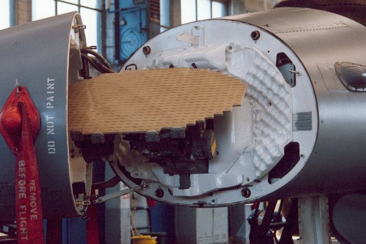
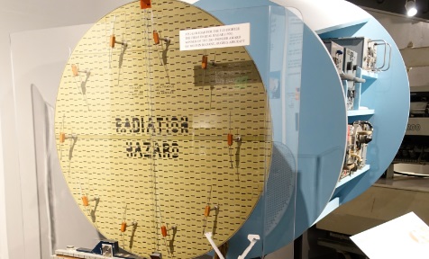
Slot antenna
Although the described antennas have a rather large gain with respect to the size of the aperture, all of them have common drawbacks: large side lobe susceptibility (susceptibility to interfering reflections from the earth's surface and sensitivity to targets with a low scattering area), a decrease in efficiency due to beam blocking (the problem with blocking is in small radars that can be used on flying vehicles; large radars, where the problem with blocking is less, cannot be used in the air). As a result, a new antenna scheme was invented - a slit. It is made in the form of a metal surface, usually flat, in which holes or slots are cut. When it is irradiated at the desired frequency, electromagnetic waves are emitted from each slot - that is, the slots act as separate antennas and form an array. Since the beam from each slot is weak, their side lobes are also very small. Slot antennas are characterized by high gain, small side lobes and low weight. They may be missing protruding parts, which in some cases is their important advantage (for example, when installed on aircraft).
Directional pattern
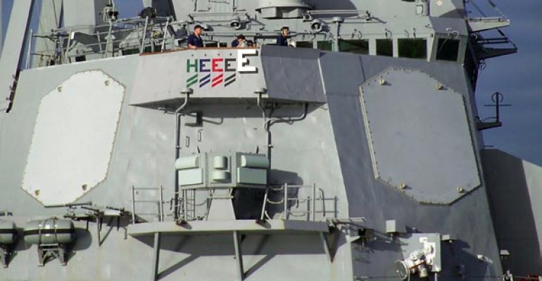
Passive phased array antenna (PFAR) [passive electronically scanned array, PESA]
Radar with MiG-31
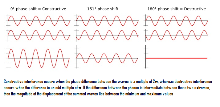
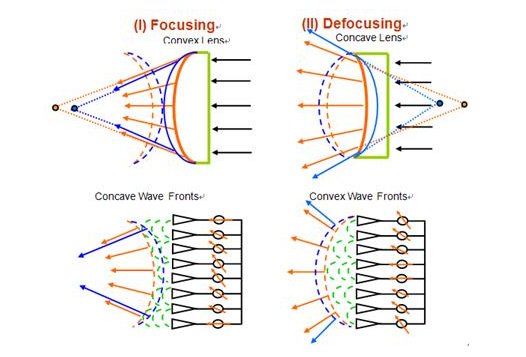
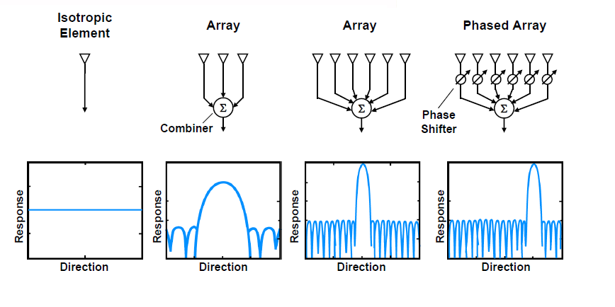
From the early days of creating radar developers, there was one problem: the balance between accuracy, range and radar scan time. It arises from the fact that radars with a narrower beam width increase accuracy (resolution increases) and range at the same power (power concentration). But the smaller the beam width, the longer the radar scans the entire field of view. Moreover, a high gain radar will require larger antennas, which is inconvenient for fast scanning. To achieve practical accuracy at low frequencies, radar would require such huge antennas that it would be difficult to turn them from a mechanical point of view. To solve this problem, a passive phased array antenna was created. It relies not on the mechanics, but on the interference of the waves to control the beam.If two or more waves of the same type oscillate and meet at one point in space, the total amplitude of the waves is added up in about the same way as the waves on the water. Depending on the phases of these waves, interference can strengthen or weaken them.
The beam can be formed and controlled electronically, controlling the phase difference of the group of transmitting elements — in this way, it can be controlled in what places the amplifying or weakening interference occurs. From this it follows that in the aircraft radar to control the beam from side to side there must be at least two transmitting elements.
Usually a radar with PFAR consists of 1 irradiator, one LNA (low-noise amplifier), one power distributor, 1000-2000 transmitting elements and an equal number of phase shifters.
Transmitting elements can be isotropic or directional antennas. Some typical types of transmitting elements:
In the first generations of fighters, patch antennas (strip antennas) were most often used , since they are the easiest to develop.
Modern active-phase arrays use flute emitters due to their broadband capabilities and improved gain:
Regardless of the type of antenna used, increasing the number of radiating elements improves the radar's directional characteristics.
As we know, with the same radar frequency, an increase in the aperture leads to a decrease in the beam width, which increases the range and accuracy. But with phased arrays it is not worth increasing the distance between the radiating elements in an attempt to increase the aperture and reduce the cost of the radar. Because if the distance between the elements is greater than the operating frequency, side lobes may appear, significantly reducing the effectiveness of the radar.
The most important and expensive part of the PPAR is phase shifters. Without them, it is impossible to control the phase of the signal and the direction of the beam.
They are of different types, but in general they can be divided into four types.
Time delay phase shifters
The simplest type of phase shifters. The signal for passing the transmission line takes time. This delay, equal to the phase shift of the signal, depends on the length of the transmission line, the frequency of the signal and the phase velocity of the signal in the transmitting material. By switching the signal between two or more transmission lines of a given length, you can control the phase shift. Switching elements are mechanical relays, pin diodes, field-effect transistors or microelectromechanical systems. Pin diodes are often used due to high speed, low losses and simple bias circuits, providing resistance changes from 10 kΩ to 1 Ω.
Delay, sec = phase shift ° / (360 * frequency, Hz)
Their disadvantage is an increase in phase error with an increase in frequency and an increase in size with a decrease in frequency. Also, the phase change varies depending on the frequency, so they are not applicable for too low and high frequencies.
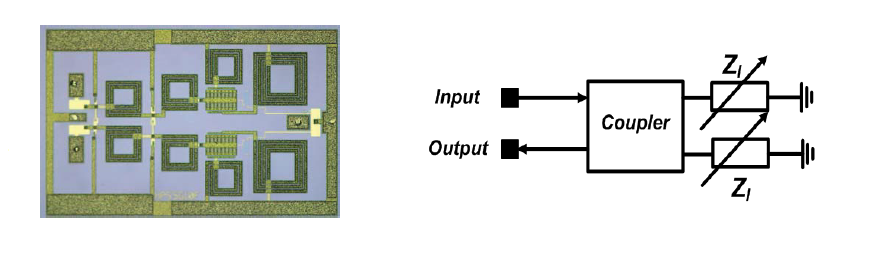
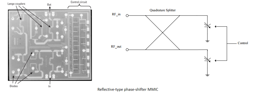
Reflective / quadrature phase shifter
Usually this is a quadrature communication device that divides the input signal into two signals that differ in phase by 90 °, which are then reflected. They are then combined in phase at the outlet. This scheme works due to the fact that the reflection of the signal from the conductive lines can be shifted in phase with respect to the falling signal. The phase shift varies from 0 ° (open circuit, zero capacity of the varactor ) to -180 ° (circuit is short-circuited, the capacity of the varactor is infinite). Such phase shifters have a wide range of work. However, the physical limitations of varactors lead to the fact that, in practice, the phase shift can only reach 160 °. But for a greater shift it is possible to combine several such chains.
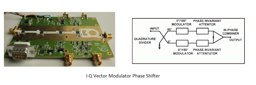
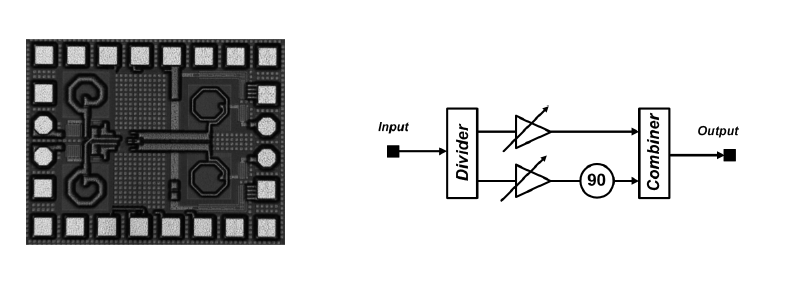
Vector IQ modulator
As with the reflective phase shifter, the signal is divided into two outputs with a 90-degree phase shift. The incoming phase without offset is called the I-channel, and the quadrature with the 90-degree offset is called the Q-channel. Each signal then passes through a two-phase modulator capable of shifting the phase of the signal. Each signal is subject to a phase shift of 0 ° or 180 °, which allows you to select any pair of quadrature vectors. Then the two signals are recombined. Since the attenuation of both signals can be controlled, the output signal controls not only the phase, but also the amplitude.
Phaser on high-pass / low-pass filters
It was made to solve the problem of phase shifters with a time delay, not capable of operating at a large frequency range. Works by switching the signal path between the high and low pass filters. It looks like a phase shifter with a time delay, only filters are used instead of transmission lines. A high pass filter consists of a series of inductors and capacitors that provide phase advance. This phase shifter provides a constant phase shift in the operating frequency range. Also, its size is much smaller than the previous phase shifters listed, so it is most often used in radars.
To sum up, compared to a conventional reflecting antenna, the main advantages of PPAR will be: high scanning speed (increasing the number of monitored targets, reducing the likelihood of detection by the radiation warning station), optimizing the target time, high gain and small side lobes (it is harder to silence and detect), random scan sequence (harder to drown out), the ability to use special modulation and detection techniques to extract the signal from the noise. The main disadvantages are high cost, the impossibility of scanning wider than 60 degrees wide (the field of view of a stationary phase array is 120 degrees, mechanical radar can expand it to 360).
Active Phased Array [Active Electronically Scanned Array, AESA]
Outside AFAR (AESA) and PFAR (PESA) is difficult to distinguish, but inside they are radically different. PFAR uses one or two high-power amplifiers that transmit one signal, which is then divided into thousands of paths for thousands of phase shifters and elements. Radar with AFAR consists of thousands of modules of reception / transmission. Since the transmitters are located directly in the elements themselves, it does not have a separate receiver and transmitter. The differences in architecture are shown in the picture.
In AFAR, most of the components, such as a weak signal amplifier, a high power amplifier, a duplexer, a phase shifter, are reduced and assembled in a single package called a receive / transmit module. Each of the modules is a small radar. Their architecture is as follows:
Although AFAR (AESA) and PFAR (PESA) use wave interference to form and deflect a beam, the unique design of AFAR provides many advantages over PFAR. For example, a weak signal amplifier is located next to the receiver, to the components where part of the signal is lost, so its signal-to-noise ratio is better than that of PPAR.
Secondly, in conventional radar, the possibility of reducing parasitic interference is limited by the errors of the instability of the equipment. Most of these errors are contributed by an analog-to-digital converter, a down-converter, high-power amplifiers, weak signal amplifiers, and a wave generator. In AFAR with a distributed group of high power amplifiers and weak signal amplifiers, such errors can be reduced. As a result, AFAR increases sensitivity in noisy environments.
Moreover, with equal detection capabilities, AFAR has less duty cycle and peak power. Also, since individual AFAR modules do not rely on a single amplifier, they can simultaneously transmit signals with different frequencies. As a result, AFAR can create several separate rays, dividing the array into sub-arrays. The ability to work on multiple frequencies brings multitasking and the ability to deploy electronic jamming systems anywhere relative to the radar. But the formation of too many simultaneous rays reduces the range of the radar.
The two main disadvantages of AFAR are the high cost and the limited field of view of 60 degrees.
Hybrid Electromechanical Phased Antenna Arrays
A very high speed scanning of the PAR is combined with a limited field of view. To solve this problem, modern radars are located on a movable disk, which increases the field of view. Do not confuse the field of view with the width of the beam. The beam width refers to the radar beam, and the field of view is the total size of the scanned space. Narrow beams are often needed to improve accuracy and range, and a narrow field of view is usually not needed.
Source: https://habr.com/ru/post/373107/
All Articles