Simple lighting controller
Oddly enough, laziness and discomfort pushed me to develop this device. Each time driving a car into the garage, in the dark, I constantly had to look for the cherished key to turn off the light in order to orient myself at the exit. As a result, I began to think about how to fix this problem. The first thing that came to mind was a ready-made motion sensor, which is used for street lighting. But I did not want the easy way, I decided to make it myself. I started scrolling through my head various solutions like a field meter on a field-effect transistor and an antenna, IR transceivers into the gateway, and as a result a thorny path led me to the well-known PIR sensor HC-SR50.
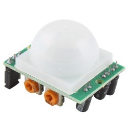
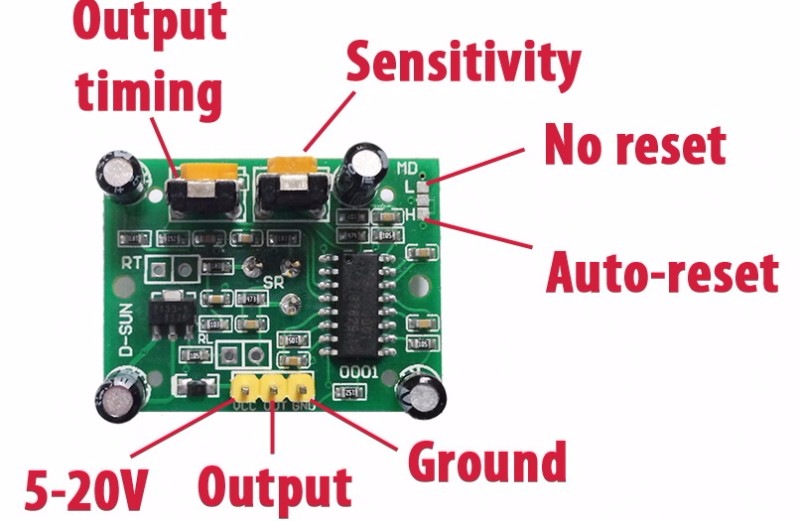
It is not expensive, its own power stabilizer (can be supplied from 5 to 20V), adjustment of the sensitivity of the detection radius (from 3 to 7 meters), angle of detection (120-140, depends on the particular lens and sensor type), adjustment of the release time, and the same two modes of operation:
1. Single capture — in this mode, when a sensor is triggered several times in a row, a high logic level remains at its output.
2. Pulse capture — in this mode, a separate pulse appears at the output at each sensor response.
')
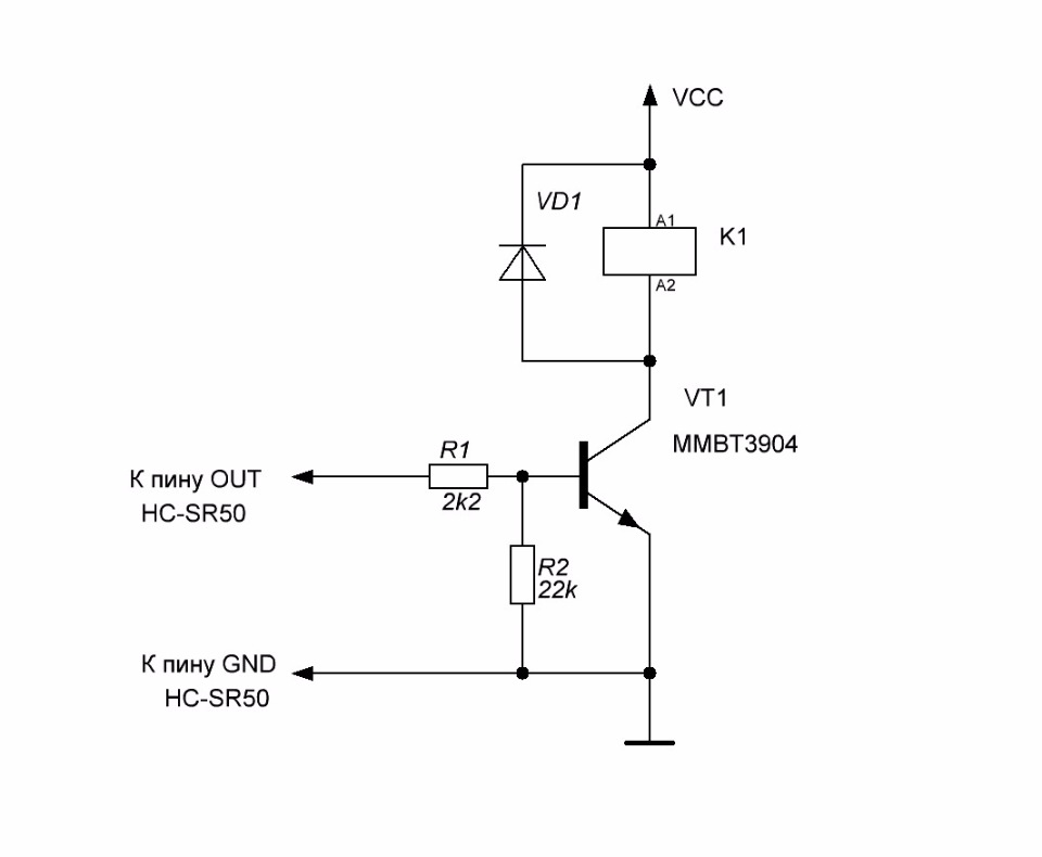
By supplying such a sensor with a dc source and a small board with a transistor switch, a pair of resistors, a diode and a relay, we get a ready device that can switch on and off our load when an object is in the sensor field.
After thinking further, I decided to use a simple Attiny13 microcontroller and link everything into one interconnected bundle: a key switch, a PIR sensor, and also added a light level sensor (discussed below).
The logic of the device:
Next, a circuit diagram was developed containing inexpensive and accessible components:
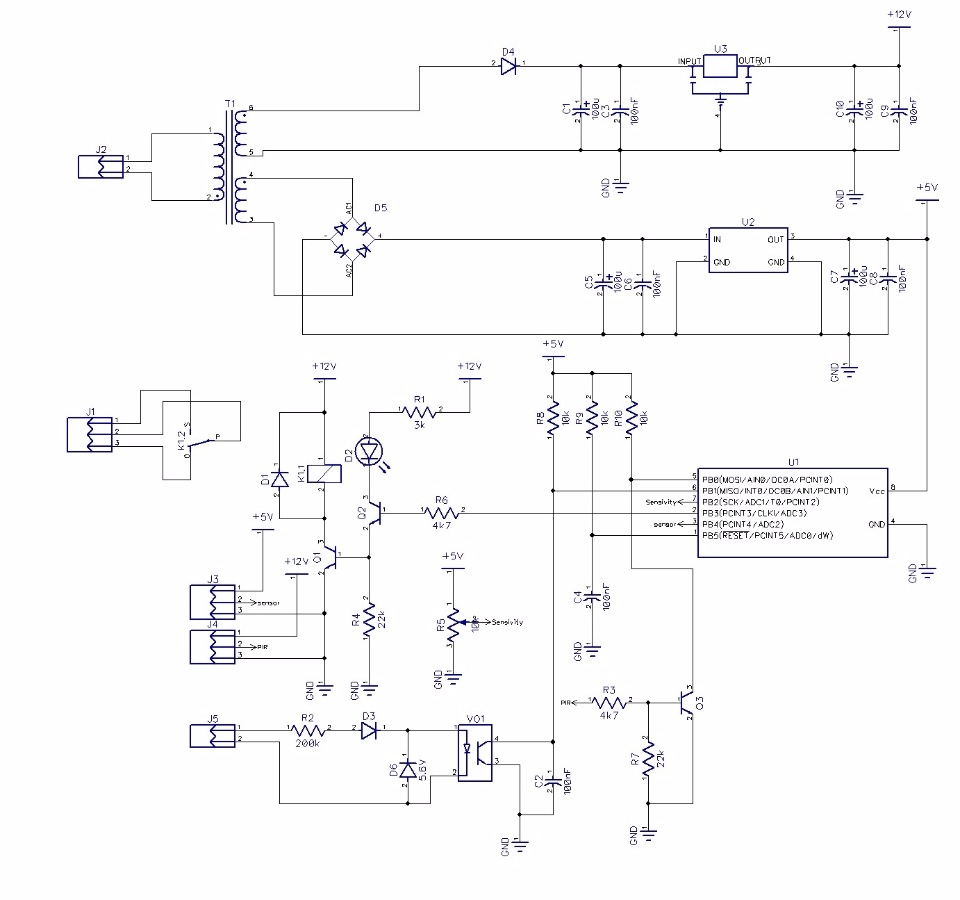
A transformer with two output windings 9V each (TPG-2) is used to power the circuit; the first winding is used to power the microprocessor part of the device and the remote light level sensor. The second winding to power the PIR sensor and the relay winding. For 12V, a half-wave rectifier and an integrated voltage regulator are used, in this case I think this scheme is justified because the PIR sensor has its own voltage regulator. Transistor Q3 is used to coordinate the levels between the PIR sensor and the microcontroller, the PIR output is an LVTTL sensor with a maximum threshold of 3.3V. Q2 transistor is used to indicate the status, Q1 transistor controls the winding of the power relay to which our lighting lamp is connected. A variable resistor is needed to adjust the sensitivity of the light sensor. Chain R2, D3, D6, C2 is necessary to capture the mains voltage from the key switch. Pulsation bounce is processed by software.
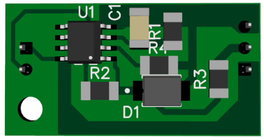
To develop the light sensor, I used an imported phototransistor from my old deposits, I don’t even know the markings, but I think such a BPW96C would be suitable. Since the device is far from the street or any opening, I couldn’t simply solder the phototransistor to the board in my case, and I didn’t risk drawing a line of the order of 10 meters to the phototransistor, therefore I made a repeater on the Rail-to-Rail operational amplifier . But then I ran into problems with calibration, in general, the phototransistor signal was very small for normal operation, and I redid the repeater on a non-inverting amplifier with a gain of 2:
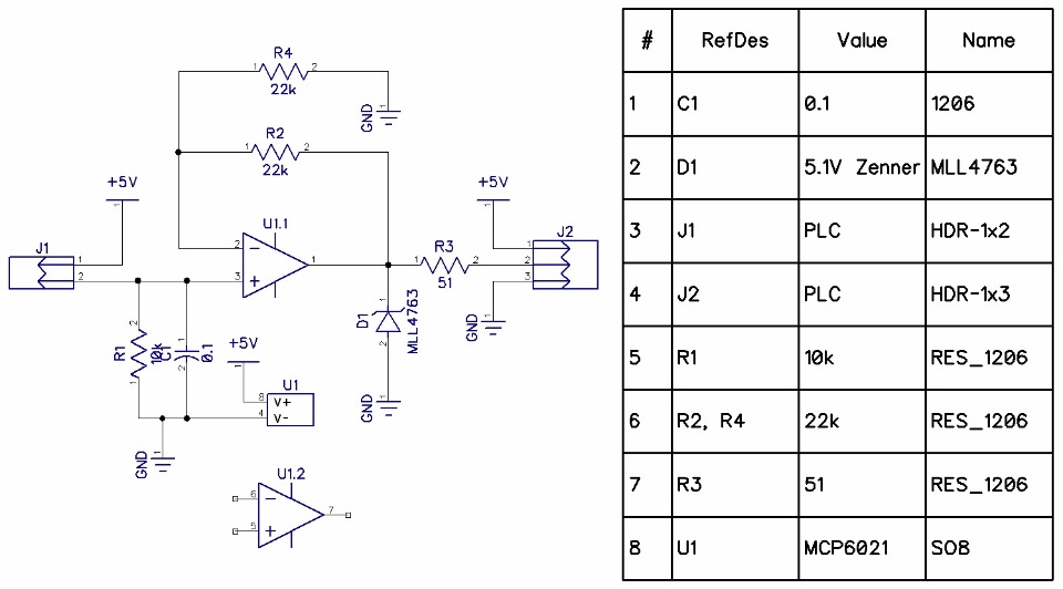
If you will repeat the design and the phototransistor will produce a suitable level, instead of the resistor R2, set the jumper 1206 with 0 value, and exclude the resistor R4 from the circuit. I had a phototransistor NPN, I connected a pin to J1-1 collector, to a pin to J1-2 emitter.
Having collected the light level sensor, I filled the board with the Vixint PC-68 compound and sat it in a heat shrink tube, leaving only the phototransistor cap with a window on the surface.
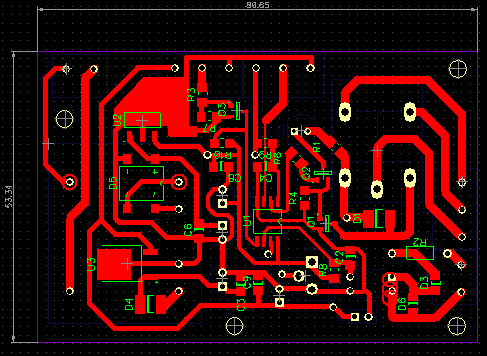
Controller PCBs:
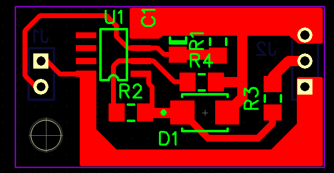
light level sensor:
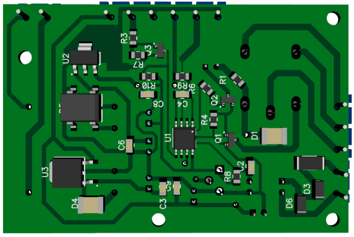
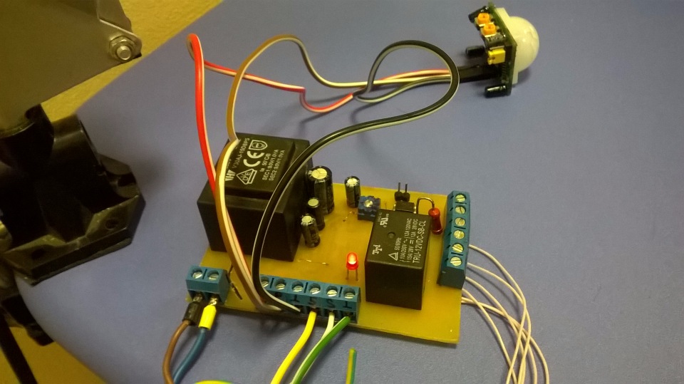
Photos of the finished device at the debugging stage:
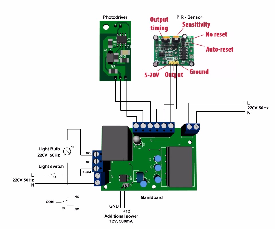
Connection diagram of all devices:
Additionally, a second PCB version was developed for a D3MG type enclosure with DIN rail installation and an AVRISP microcontroller programming connector (in the first version I soldered the wires with the connector to the board for programming). The microcontroller firmware is written in C in Atmel Studio.
The source code, two versions of printed circuit boards and electrical schematics with lists of components (CAD used is Dip Trace 3.0.0.1), as well as a simulation file for Proteus 8 you can find in the repository - LightController .
PS: before installation, the controller and the PIR sensor, just in case, opened up two layers of cap-varnish. The device is connected to the network through a circuit breaker (the nominal value depends on the consumption of the lamps), in my case the circuit breaker is connected via a circuit breaker of 2 A.
It is not expensive, its own power stabilizer (can be supplied from 5 to 20V), adjustment of the sensitivity of the detection radius (from 3 to 7 meters), angle of detection (120-140, depends on the particular lens and sensor type), adjustment of the release time, and the same two modes of operation:
1. Single capture — in this mode, when a sensor is triggered several times in a row, a high logic level remains at its output.
2. Pulse capture — in this mode, a separate pulse appears at the output at each sensor response.
')
By supplying such a sensor with a dc source and a small board with a transistor switch, a pair of resistors, a diode and a relay, we get a ready device that can switch on and off our load when an object is in the sensor field.
After thinking further, I decided to use a simple Attiny13 microcontroller and link everything into one interconnected bundle: a key switch, a PIR sensor, and also added a light level sensor (discussed below).
The logic of the device:
- The priority of switching on is always at the key switch, regardless of the level of illumination and the location of the object in the field of the PIR sensor.
- After about 5 hours, when the key switch is on, the light will automatically turn off. Sometimes the household, and sometimes I myself forget to turn off the light.
- If the key switch is turned off, the object is in the PIR sensor field and it is dark outside (a photo sensor comes to the rescue), the light turns on, and turns on until the object leaves the PIR sensor field.
- If the key switch is turned off, the object is in the PIR sensor field and it is dark outside, the light turns on, and lights up, if the object leaves the PIR sensor field, the lighting continues to operate during the time interval set by the adjustment potentiometer on the PIR sensor from 5 seconds to 300 seconds
- If the key switch is turned off, the object is in the PIR sensor field and it is light on the street, the light will not turn on until the light level drops to a predetermined threshold or the key switch turns on.
Next, a circuit diagram was developed containing inexpensive and accessible components:
A transformer with two output windings 9V each (TPG-2) is used to power the circuit; the first winding is used to power the microprocessor part of the device and the remote light level sensor. The second winding to power the PIR sensor and the relay winding. For 12V, a half-wave rectifier and an integrated voltage regulator are used, in this case I think this scheme is justified because the PIR sensor has its own voltage regulator. Transistor Q3 is used to coordinate the levels between the PIR sensor and the microcontroller, the PIR output is an LVTTL sensor with a maximum threshold of 3.3V. Q2 transistor is used to indicate the status, Q1 transistor controls the winding of the power relay to which our lighting lamp is connected. A variable resistor is needed to adjust the sensitivity of the light sensor. Chain R2, D3, D6, C2 is necessary to capture the mains voltage from the key switch. Pulsation bounce is processed by software.
To develop the light sensor, I used an imported phototransistor from my old deposits, I don’t even know the markings, but I think such a BPW96C would be suitable. Since the device is far from the street or any opening, I couldn’t simply solder the phototransistor to the board in my case, and I didn’t risk drawing a line of the order of 10 meters to the phototransistor, therefore I made a repeater on the Rail-to-Rail operational amplifier . But then I ran into problems with calibration, in general, the phototransistor signal was very small for normal operation, and I redid the repeater on a non-inverting amplifier with a gain of 2:
If you will repeat the design and the phototransistor will produce a suitable level, instead of the resistor R2, set the jumper 1206 with 0 value, and exclude the resistor R4 from the circuit. I had a phototransistor NPN, I connected a pin to J1-1 collector, to a pin to J1-2 emitter.
Having collected the light level sensor, I filled the board with the Vixint PC-68 compound and sat it in a heat shrink tube, leaving only the phototransistor cap with a window on the surface.
Controller PCBs:
light level sensor:
Photos of the finished device at the debugging stage:
Connection diagram of all devices:
Additionally, a second PCB version was developed for a D3MG type enclosure with DIN rail installation and an AVRISP microcontroller programming connector (in the first version I soldered the wires with the connector to the board for programming). The microcontroller firmware is written in C in Atmel Studio.
The source code, two versions of printed circuit boards and electrical schematics with lists of components (CAD used is Dip Trace 3.0.0.1), as well as a simulation file for Proteus 8 you can find in the repository - LightController .
PS: before installation, the controller and the PIR sensor, just in case, opened up two layers of cap-varnish. The device is connected to the network through a circuit breaker (the nominal value depends on the consumption of the lamps), in my case the circuit breaker is connected via a circuit breaker of 2 A.
Source: https://habr.com/ru/post/373029/
All Articles