We write our firmware for Sonoff TH10 / 16 modules
Recently on Geektimes there was a review about ITEAD TH10 modules . I want to share the experience of developing their own firmware for these devices.
SONOFF is a series of switches, sockets and other devices of the “Internet of Things” category from ITEAD . They are characterized by a fairly low price, the use of the “people's WiFi module” ESP8266 and work in its own service, located in the cloud Amazon AWS global server.
For these modules there are third-party firmware. For example, the MQTT OTA collected from the ESP SDK or the same but in the Arduino IDE
I want to share the experience of creating my own firmware for Sonnoff in the Ardiono IDE environment.
')
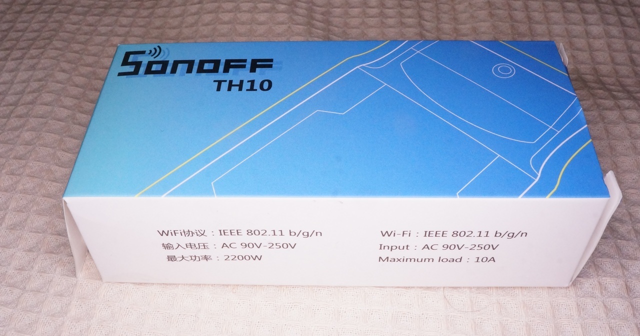
I liked the Sonoff modules right away. Starting from packaging:
Appearance:
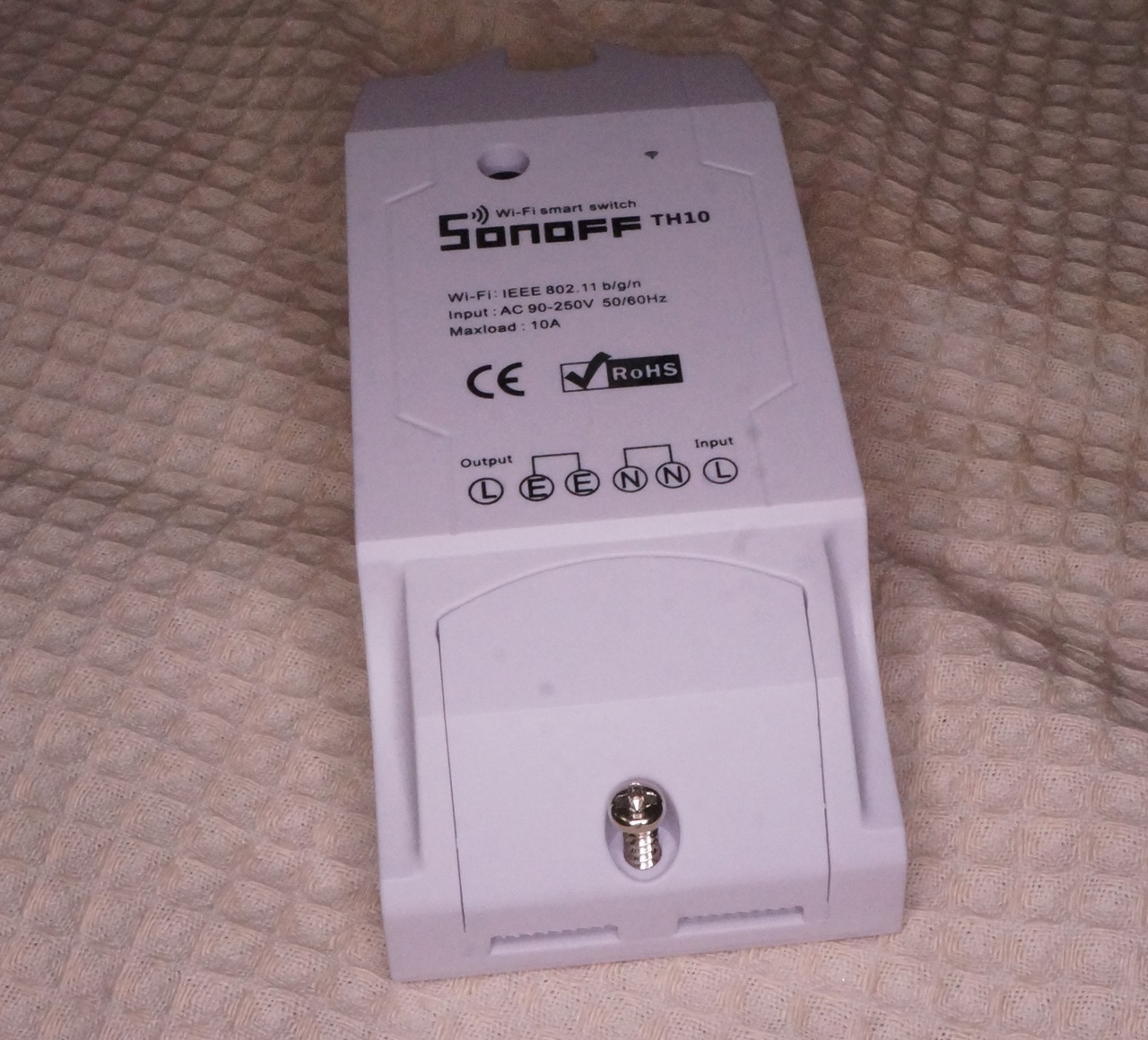
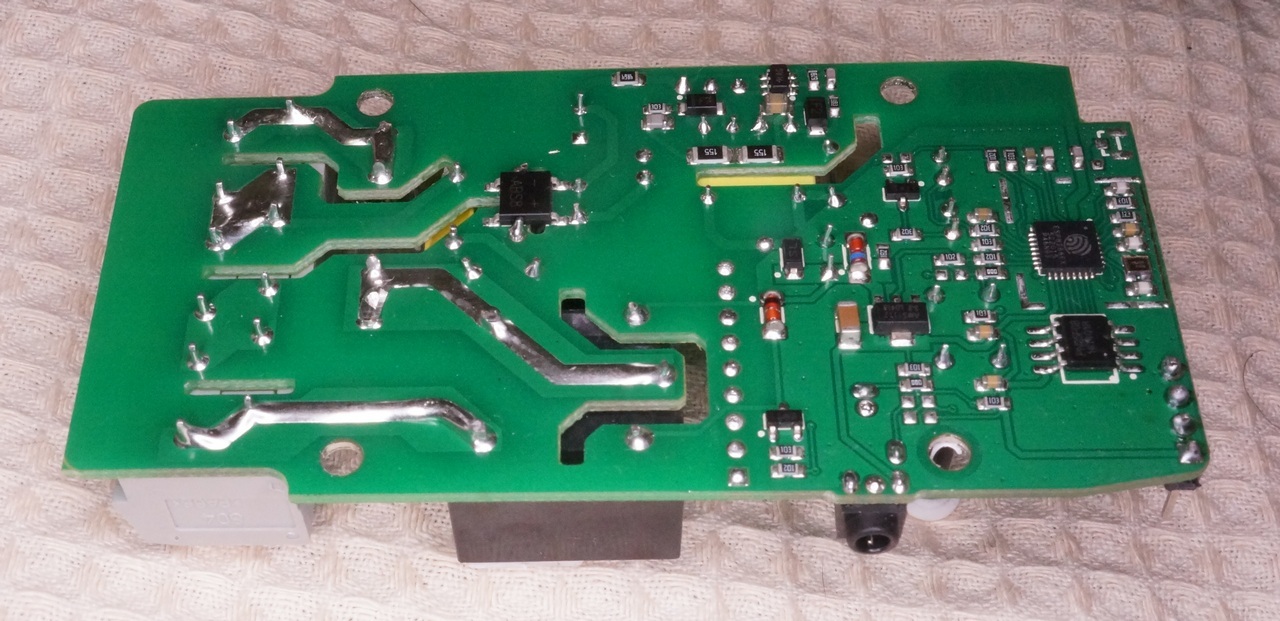
High-quality assembly and soldering:
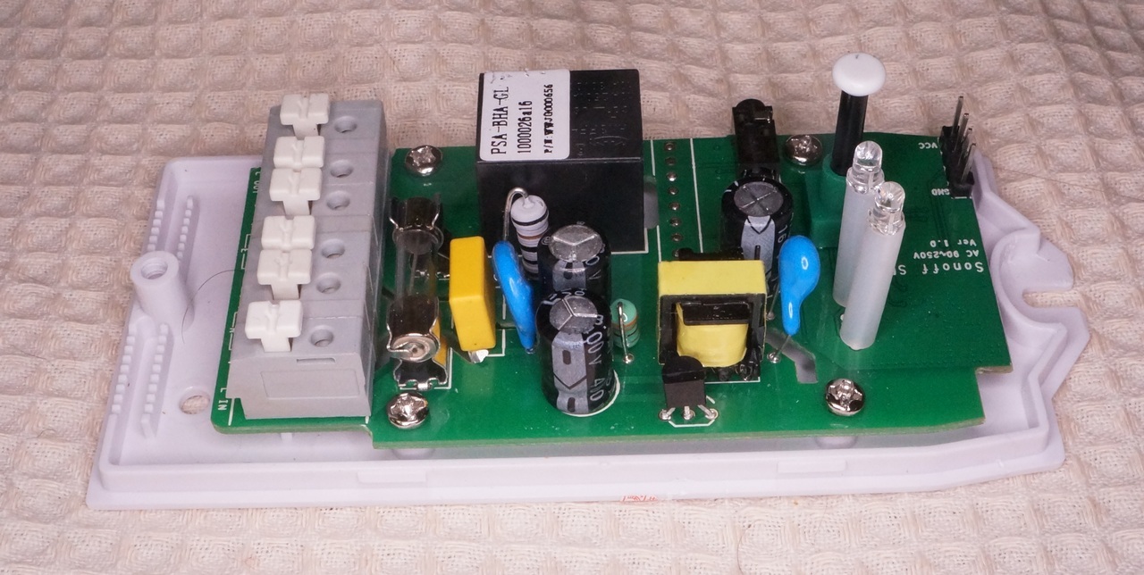
And ending with a sophisticated circuitry , in which the transistors for load control, pull-up and matching resistors and conders clearly did not spare.

With the support and documentation of its devices, ITEAD can plug many famous manufacturers into the belt, not bothering to publish technical details on their hardware. And the list of ITEAD products is quite impressive.
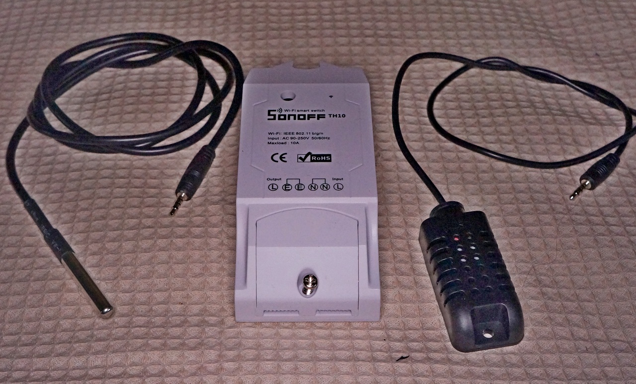
In essence, the Sonoof TH10 / 16 is an ESP8266 with a network power supply unit, peripherals in the form of relays, LEDs, temperature and humidity sensors, with a connection block and in a decent package.
I’ll omit the description of how to connect Sonoff to a cloud service and manage the eWeLink application on a smartphone. In my opinion, it is completely inapplicable when control of controllers depends on the Internet and account in some cloud, even on Amazon servers. Therefore, we leave the eWeLink application to demonstrate the capabilities of Sonoff and write our control program.
To do this, you need to solder the 4-pin connector for connecting to a USB / TTL converter.

Having a negative experience of flashing Sonoff POW, I highly recommend that all programming work be carried out with the Sonoff power section disconnected and powered via pin 3.3V.
My last USB / TTL heroically died along with the Sonoff POW module, so I’m using an Arduino UNO with a RESET plugged in to connect to the ground. The 3.3-volt Una stabilizer does an excellent job with the ESP8266 load and the entire periphery of the module.

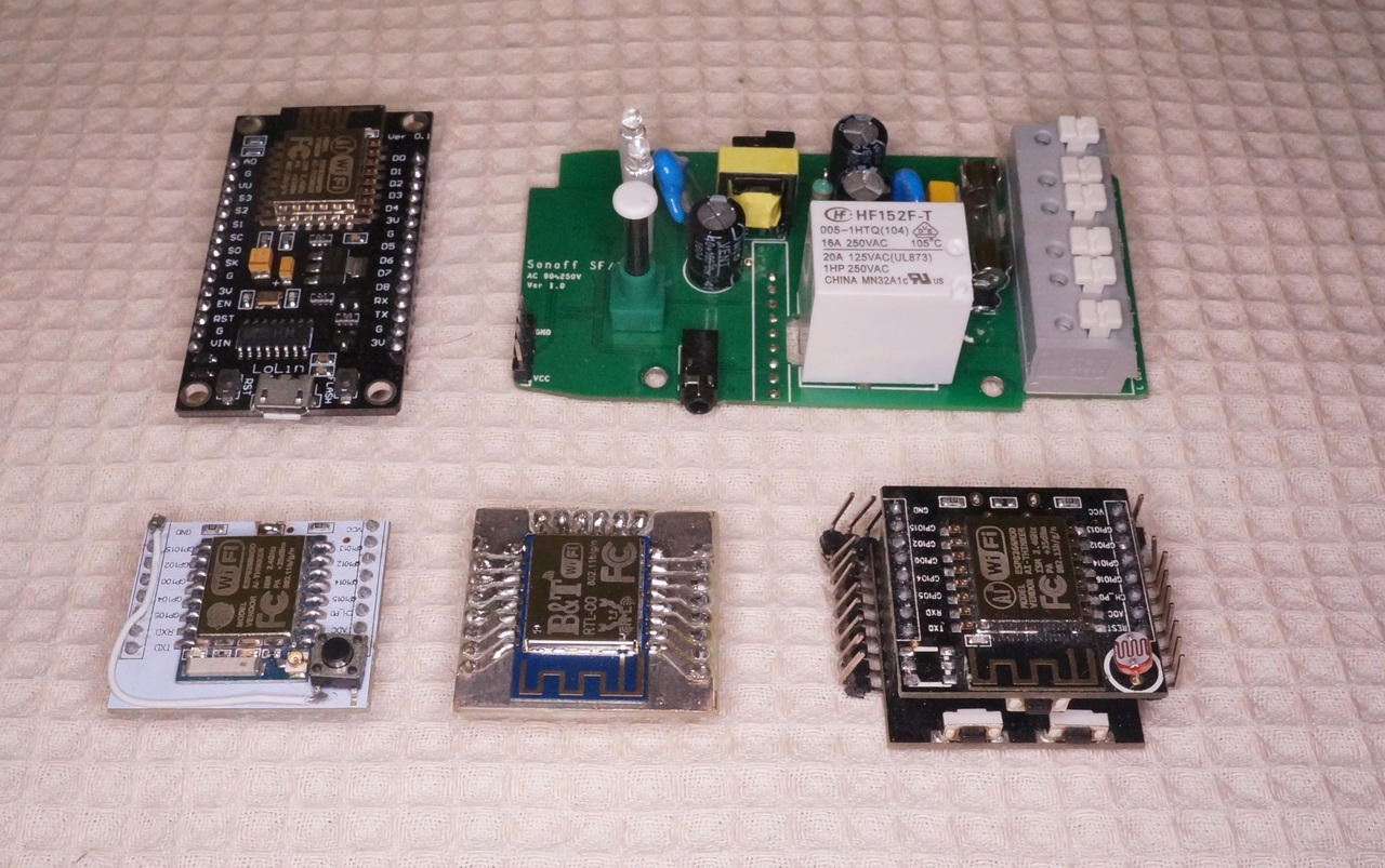
As a development environment, I will use the Arduino IDE for the ease of installation and abundance of ready-made libraries and examples, although as an experienced programmer I still think that VI and make is enough for developing programs of any complexity))).
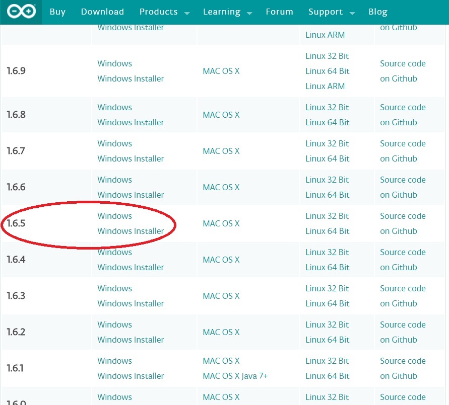
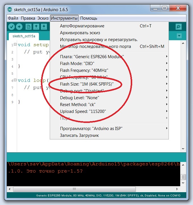
How to install the ESP8266 Cire for Arduiono IDE devoted a lot of material on the Internet. From myself I want to recommend the version of Arduino IDE 1.6.5 , as having the least glitches when working with ESP.
Since the board has a 1 MB memory chip installed, select the appropriate configuration when booting into the Board Manager:
Now it is enough to press the Sonoff controller button and distort the power, the device switches to the firmware download mode.
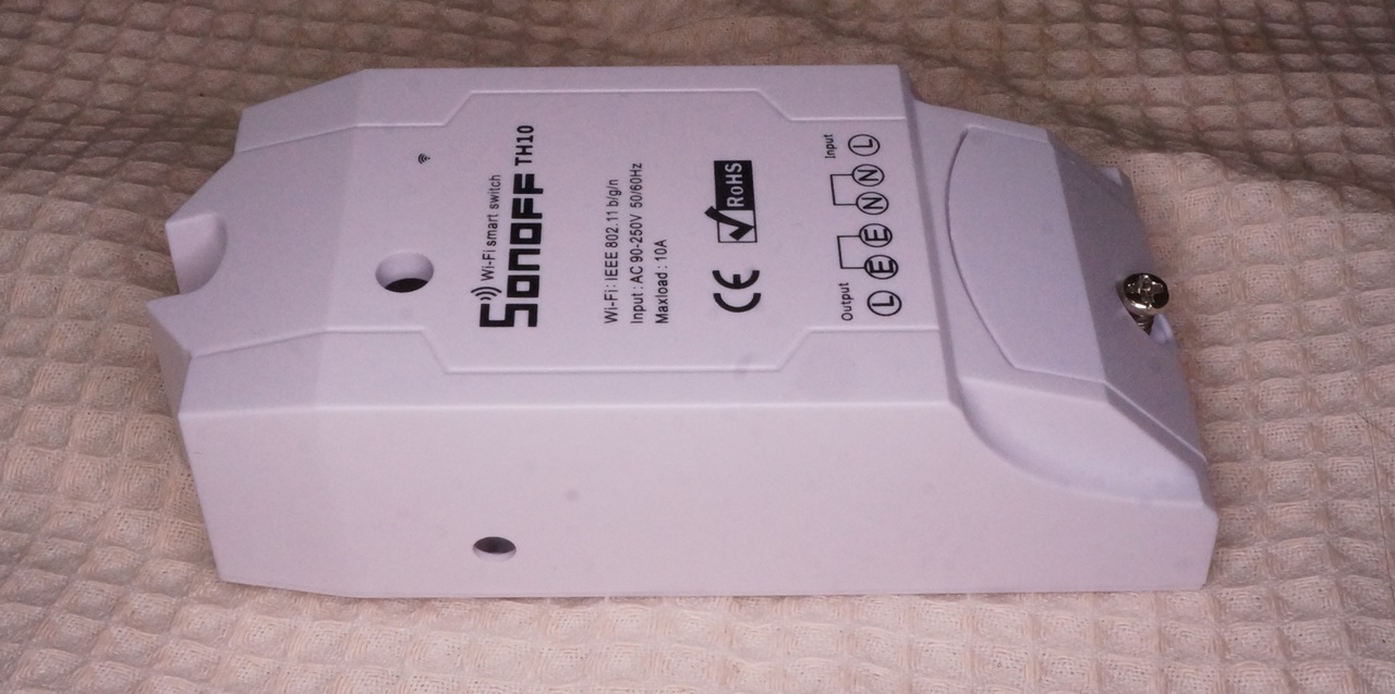
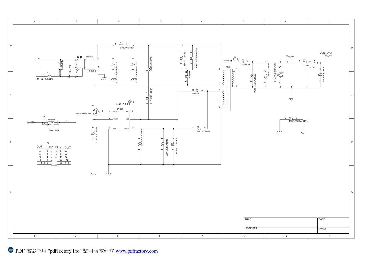
In order to program the controller itself, you need to understand which ports are connected to what. To do this, you can use the scheme on the ITEAD website, the link to which I gave above and the tester.
So, what we have:
GPIO0 - button (this is understandable when we turned on the bootloader)
GPIO12 - red LED and relay
GPIO13 - Blue LED
GPIO14 and GPIO4 are connected to the sensor connector.
Moreover, both sensors are single-wire and use GPIO14. GPIO4 still needs to be enabled with a jumper on the board.
Yes. Not much, although more than ESP01.
GPIO2 and GPIO15 have pull-up resistors on the board, you can solder to them. GPIO5 and ADC are not soldered at all, and you need to connect directly to the ESP chip. Leave these four outputs alone and proceed to programming.
Sketch blinking LEDs on sonoff
/** * SONOFF TH10/16 * Copyright 2016 * http://samopal.pro */ #include <arduino.h> uint8_t PIN_RELAY = 12; uint8_t PIN_LED2 = 13; void setup() { pinMode(PIN_RELAY,OUTPUT); pinMode(PIN_LED2, OUTPUT); } LEDs work in antiphase. Blue lights up when it is low. The relay should not operate due to lack of 5V power. In the future, I will use a blue LED to display various modes. I wrote about this in detail in this article.
I will not dwell on the button in detail. Yes, the control buttons, I wrote a convenient library that catches long and short press, auto-repeat with a long press and presses the bounce of contacts. I described all this in detail in my blog .
Now the sensors. I was sent a temperature / humidity sensor AM2301 and a DS18B20 temperature sensor in a waterproof design.
AM2301 is compatible with the DHT21 sensor. His work requires a DHT library. There are a lot of Forks of the DHT library, I recommend taking the version from Adafruit in which there is an autotune on the controller frequency and which works correctly on ESP8266 .
Sketch work with the sensor AM2301
/** * SONOFF TH10/16 * Copyright 2016 * http://samopal.pro */ #include <arduino.h> // DHT Adafruit // https://github.com/adafruit/DHT-sensor-library #include <DHT.h> uint8_t PIN_DHT = 14; DHT dht(PIN_DHT, AM2301); void setup() { // Serial.begin(115200); Serial.printf("DHT init ..."); dht.begin(); } void loop() { delay(1000); Serial.print("Temperature="); Serial.print(dht.readTemperature(),1); Serial.println(" C"); Serial.print("Humidity="); Serial.print(dht.readHumidity(),0); Serial.println("%"); } 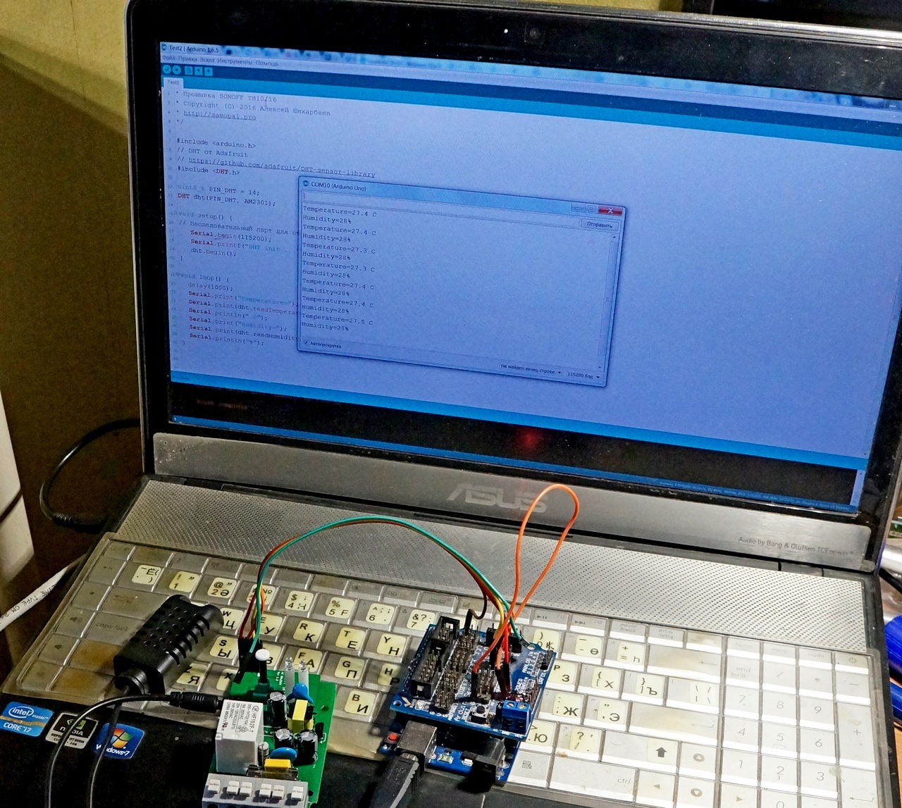
To connect to the DS18B20, the OneWire library is needed. Fully compatible with ESP multiplatform version of this library.
The algorithm for polling the sensor is taken from the example:
Sketch work with sensor DS18B20
/** * SONOFF TH10/16 * Copyright 2016 * http://samopal.pro */ #include <arduino.h> // // https://github.com/PaulStoffregen/OneWire #include <OneWire.h> #define ERROR_VALUE 2147483647 float GetDS18X20(); uint8_t PIN_DS = 14; OneWire ds(PIN_DS); void setup() { // Serial.begin(115200); Serial.printf("DS18B20 init ..."); } void loop() { delay(1000); float t = GetDS18X20(); if( t!= ERROR_VALUE ){ Serial.print("Temperature="); Serial.print(t,1); Serial.println(" C"); } } /** * */ float GetDS18X20(){ byte i; byte present = 0; byte type_s; byte data[12]; byte addr[8]; float celsius; if ( !ds.search(addr)) { // Serial.println("DS18B20: No more addresses."); ds.reset_search(); delay(250); return ERROR_VALUE; } if (OneWire::crc8(addr, 7) != addr[7]) { // Serial.println("DS1820: CRC is not valid!"); return ERROR_VALUE; } // the first ROM byte indicates which chip switch (addr[0]) { case 0x10: type_s = 1; break; case 0x28: type_s = 0; break; case 0x22: type_s = 0; break; default: // Serial.println("Device is not a DS18x20 family device."); return ERROR_VALUE; } ds.reset(); ds.select(addr); ds.write(0x44, 1); // start conversion, with parasite power on at the end delay(1000); // maybe 750ms is enough, maybe not // we might do a ds.depower() here, but the reset will take care of it. present = ds.reset(); ds.select(addr); ds.write(0xBE); // Read Scratchpad for ( i = 0; i < 9; i++) { // we need 9 bytes data[i] = ds.read(); } // Convert the data to actual temperature // because the result is a 16 bit signed integer, it should // be stored to an "int16_t" type, which is always 16 bits // even when compiled on a 32 bit processor. int16_t raw = (data[1] << 8) | data[0]; if (type_s) { raw = raw << 3; // 9 bit resolution default if (data[7] == 0x10) { // "count remain" gives full 12 bit resolution raw = (raw & 0xFFF0) + 12 - data[6]; } } else { byte cfg = (data[4] & 0x60); // at lower res, the low bits are undefined, so let's zero them if (cfg == 0x00) raw = raw & ~7; // 9 bit resolution, 93.75 ms else if (cfg == 0x20) raw = raw & ~3; // 10 bit res, 187.5 ms else if (cfg == 0x40) raw = raw & ~1; // 11 bit res, 375 ms //// default is 12 bit resolution, 750 ms conversion time } celsius = (float)raw / 16.0; return celsius; } 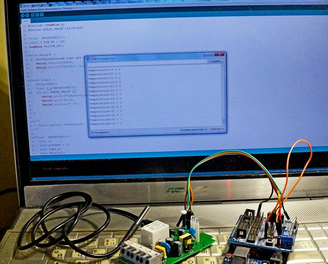
Well, the periphery works. Next, I use my existing experiences. Completely all the firmware can be taken from here.
Features of the firmware:
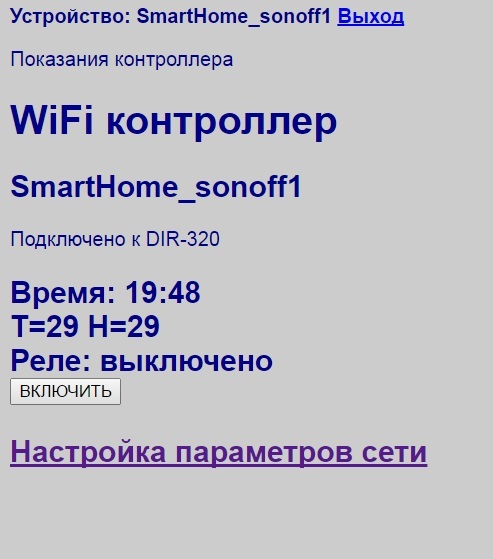
- Automatic detection of sensors AM2301 and DS18B20
- Long press the button - on / off access point mode
- A short press of a button - on / off relay
- Blue LED is on - connection established, double flash - no connection, single flash - access point mode
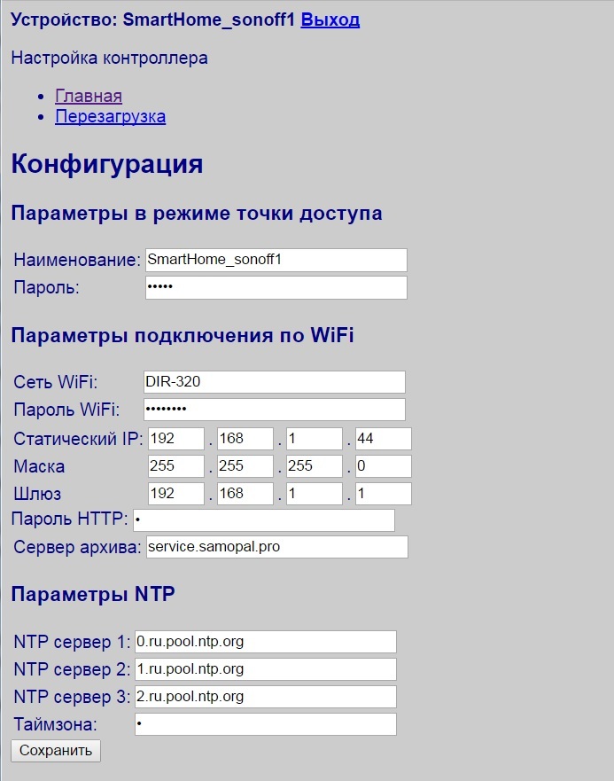
- Local WEB server in access point mode 192.168.4.1
- when connecting to WiFi at the IP address that is configured
- Authorization of access by password. By default admin / 12345
- Saving parameters to a server on the Internet using a regular HTTP request. You can configure any server, for example, national monitoring. And you can also local without any Internet.
- Saving settings to EEPROM
- When connecting to the Internet, setting the time by NTP
For lovers of ready services. the ready-made library MQTT, BLYNK, etc. is easily screwed. But this is already beyond the scope of this article.
Total
SONOFF is a convenient platform primarily for those who can independently develop and modify control programs.
For those familiar with the ESP8266 - Sonoff is the savings on assembly, soldering and parts, provided that you need just such a device configuration, as laid down in a specific Sonoff module.
The biggest disadvantage of these modules is that part of the GPIO is not divorced into connectors. Well, ITEAD company should make a comb with 8 pin and get there all the free GPIO from ESP. I think the popularity of such modules at the current price would greatly increase.
As for specific applications, such a controller can be fully implemented on the Sonoff TH10 module.
Source: https://habr.com/ru/post/372773/
All Articles