What will happen if you apply a direct current to the grid?
 The war of currents is over, and Tesla and Westinghouse seem to have won. DC networks are now used somewhere on the railway, as well as in the form of high-voltage transmission lines.
The vast majority of grids operate on alternating current. But let's imagine that instead of alternating voltage with a current value of 220 volts, the same 220 V, but direct current, suddenly began to flow into your house.
The theater begins with a hanger, and our electric circus starts with an opening shield.
Automatic machines
And at once the good news: the security machines will work as expected. The automatic machine has two releases: thermal and electromagnetic. Thermal serves to protect against prolonged overload. The current heats the bimetallic plate, it bends and opens the circuit. The electromagnetic element is triggered by a short current pulse during a short circuit. It is a solenoid that draws in the core and, again, breaks the circuit. Both of these systems work great with direct current.
')

image source: automatic switch. rf
Additions from Bronx and AndrewN :
The magnetic release triggers according to the amplitude value of the current, that is, 1.4 times the current. On DC, its current will be 1.4 times higher.
The DC arc is more difficult to extinguish, so that if a short circuit occurs, the time to open the circuit will increase and the automaton's wear will accelerate. There are special machines designed to work with direct current.
UZO
In addition to automata, there is a safety shutdown device (RCD) in the shield. Its purpose is to detect the leakage of current from the network to the ground, for example, when a person touches current-carrying parts. RCD measures the current in two conductors passing through it. If the same current flows into the load as it flows out - everything is in order, there is no leakage. If the currents are not equal, the RCD sounds an alarm and breaks the circuit.
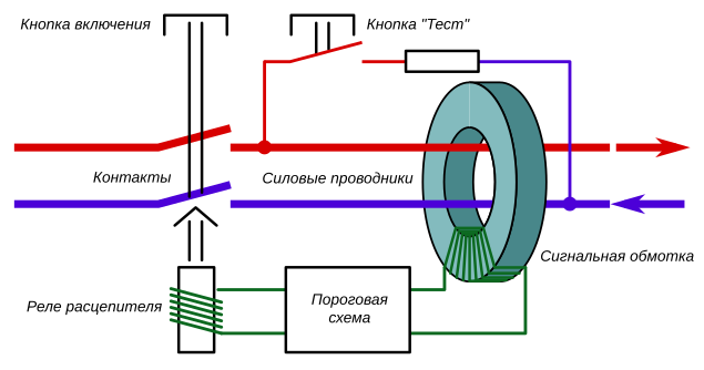
Sensitive element of the RCD - differential transformer. Such a transformer has two primary windings connected in opposite directions. If the currents are equal, their magnetic fields compensate each other and there is no signal at the output. If the currents are not compensated, a voltage appears at the output of the signal winding, to which the RCD circuit responds. At DC, the transformer will not work, and the RCD will be useless.
Counter
No matter what your electricity meter is - old mechanical or new electronic - it will not work. The mechanical counter is an electric motor, where the metallic disk serves as a rotor, and the stator contains two windings. One winding is connected in series with the load and measures the current, the second is connected in parallel and measures the voltage. Thus, the more power consumption, the faster the disk turns. The operation of such a counter is based on the phenomenon of electromagnetic induction, and at constant current in the windings the disk will remain motionless.
The electronic meter is arranged differently. It directly measures the voltage (through a resistive divider) and current (using a shunt or Hall sensor), digitizes them, and then the microprocessor recalculates the data in kilowatt-hours. In principle, nothing prevents such a scheme from working with direct current, but in all household meters the constant component is programmatically filtered out and does not affect the readings. DC meters exist in nature, they are placed, for example, on electric locomotives, but you will not find one in a flat panel.
Well, okay, not enough to pay for all this mess! We go further along the chain and see which electrical appliances we can meet.
Heating appliances
Everything is beautiful here. An electric heater is a purely resistive load, and the thermal effect of the current does not depend on its shape and direction. Electric stoves, kettles, boilers, irons and soldering irons will work on direct current in the same way as on alternating current. Bimetallic thermostats (as, for example, in an iron) will also function correctly.
Incandescent lamps
The good old Ilyich light bulb on a direct current feels no worse than an alternating current. Even better: there will be no pulsations of light, the lamp will not buzz. On an alternating current, a light bulb can buzz due to the fact that the coil (especially if it is slack) works like an electromagnet, compressing and stretching twice during the period. When powered by a constant current of this unpleasant phenomenon will not.
However, if you have brightness controls (dimmers) installed, they will stop working. The key element of the dimmer is a thyristor - a semiconductor device that opens and begins to pass current at the moment of applying the control pulse. The thyristor closes when the current stops flowing through it. When the thyristor is supplied with alternating current, it will close at each current flowing through zero. By giving a control pulse at different times relative to this transition, it is possible to change the time during which the thyristor will be open, and hence the power in the load. That is how dimmer works.

When powered by direct current, the thyristor will not be able to close, and the lamp will always be lit at 100% power. Or perhaps the control circuit will not be able to “catch” the transition of the mains voltage through zero and will not give an impulse to open the thyristor. Then the lamp does not light up at all. In any case, the dimmer will be useless.
Fluorescent lamps
The fluorescent lamp can not be switched on directly in the network, for normal operation it needs a starting control device (PRA). In the simplest case, it consists of three parts: the starter, the throttle and the capacitor. The latter is needed not by the lamp itself, but by the rest of consumers in the network, since it improves the power factor and filters the noise generated by the lamp. A starter is a neon light bulb, one of the electrodes of which bends when it is heated and touches the second electrode. The choke is a large inductor connected in series with the lamp:
Normally, all this works like this: when turned on, the discharge in the starter ignites, its contacts heat up and close together. The current flows through the filaments of the lamp, causing them to heat up and begin to emit electrons. At this time, the starter cools down and opens the circuit. The current drops sharply, and due to self-induction, a high voltage pulse appears on the choke. This pulse ignites the discharge in the lamp, and then it burns on its own. The choke now limits the discharge current, working as additional resistance.
What will be on a direct current? The starter will work, the lamp will light as it should be, but then everything will go awry. In the DC circuit, the inductor will not have inductive resistance (only the active resistance of the wires, but it is small), which means that it will no longer be able to limit the current. The higher the discharge current, the more ionized the gas in the lamp, the resistance drops, and the current increases even more. The process will develop like an avalanche and end with the explosion of a lamp.
Lamps with electronic control gear
Electromagnetic ballasts are simple, but not without flaws. They have low efficiency, the throttle is bulky and heavy, buzzes and heats up, the lamp lights up with wild blinking, and then flickers with a frequency of 100 Hz. All these deficiencies deprived of the electronic control gear (ECG). How does he work? If you look at the schemes of various electronic ballasts , you can notice the general principle. The network voltage is rectified (converted to constant), then the transistor or microcircuit generator produces an alternating high-frequency voltage (tens of kHz), which feeds the lamp. In expensive electronic ballasts, there are schemes for heating up the threads and a smooth start that prolong the lamp life.
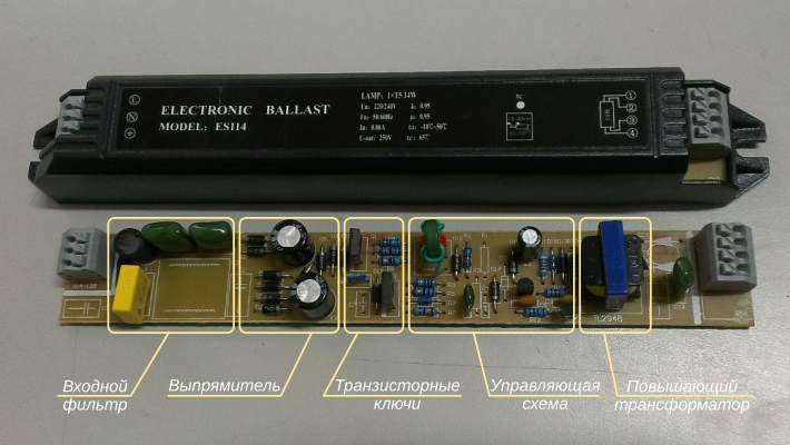
image source: aliexpress.com
Both linear lamp units and compact “energy-saving”, which are screwed into a conventional cartridge, have similar circuitry. Since the rectifier is at the input of the ECG, it is possible to feed the entire circuit with a constant voltage.
LED bulbs
The LED requires a small constant voltage for operation (about 3.5 V, usually several diodes are connected in series) and a current limiter. Schemes of LED lamps are very diverse, from simple to fairly complex.
The simplest thing is to install a damping resistor in series with the LEDs. It will drop excess voltage, it will also limit the current. Such a circuit has a monstrously low efficiency, so in practice, instead of a resistor, a quenching capacitor is installed. It also has resistance (for alternating current), but thermal power is not dissipated on it. According to this scheme assembled the cheapest lamps. LEDs in them flicker with a frequency of 100 Hz. At DC such a lamp will not work, because for DC capacitor has an infinite resistance.
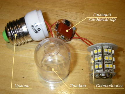
image source: bigclive.com
More expensive lamps are more complicated, very similar to electronic ballasts for fluorescent lamps. The power source in them contains a high-frequency switching regulator, which is powered by rectified mains voltage. As in the case of electronic ballasts, the circuit will work normally if you apply a constant voltage to it.
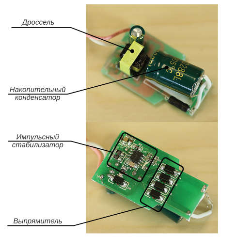
image source: powerelectronictips.com
Universal collector engines
The universal collector motor (UCD) consists of a fixed stator and a rotor that rotates inside. The stator has one winding, and the rotor is several at once. The rotor windings are connected through a collector - a cylinder with contacts, on which carbon brushes slide. The interaction of the magnetic fields of the stator and the rotor causes the rotor to turn. The collector is designed so that all the time includes the one of the windings, which is perpendicular to the stator winding - for it the torque is maximum.
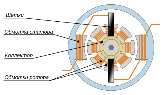
Such an engine can operate when powered by both alternating and direct current. Actually, that's why it is called “universal”. When the polarity is changed, the direction of the magnetic field changes simultaneously in both the stator and the rotor, as a result, the motor continues to rotate in the same direction. At a constant current, the DCB develops an even greater moment than at an alternating current due to the absence of inductive resistance of the windings. Universal collector engines are used where you need to get more power with small dimensions. In household appliances, UCDs are found in washing machines, vacuum cleaners, hair dryers, blenders, mixers, meat grinders, and also in power tools. All these devices will continue to work if the voltage in the outlet suddenly "straightens up".
Synchronous motors
A synchronous motor in the stator has several windings that create a rotating magnetic field. The rotor contains a permanent magnet or a winding fed by direct current. The magnetic field of the stator engages with the rotor field and rotates it behind him. A feature of this engine is that its rotational speed depends only on the frequency of the supply current. At DC, obviously, such a motor will rotate with zero frequency, that is, it will stop.
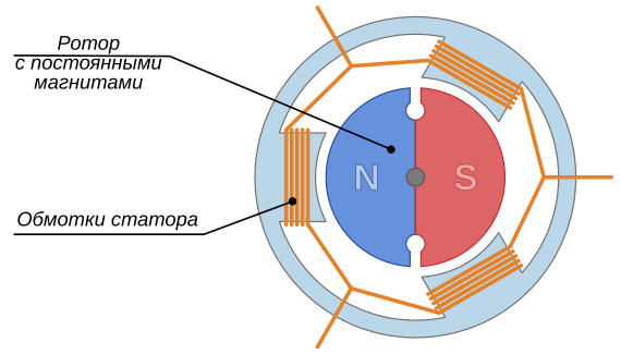
In everyday life, low-power synchronous motors are used wherever it is necessary to maintain a strictly constant rotational speed. These are mainly electromechanical clocks and timers. Also synchronous are the motor of rotation of the dish in the microwave oven and the motor of the drain pump in the washing machine.
Asynchronous motors
Asynchronous motor is similar to its synchronous device. It also has a stator several windings and creates a rotating field. But the rotor winding is not connected anywhere and shorted. The current in it is created due to the phenomenon of electromagnetic induction in the alternating field of the stator. This current creates its own magnetic field, which interacts with the rotating field of the stator and causes the rotor to rotate.
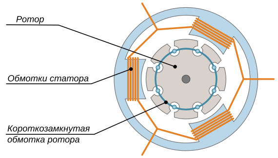
Asynchronous motors are distinguished by low noise and a large resource due to the absence of rubbing brushes. They can be found in refrigerators, air conditioners and fans. When powered by direct current, the magnetic field of the stator will not rotate. There will also be no current in the squirrel-cage rotor. The engine will remain motionless, and the winding will simply heat up, like a normal piece of wire.
Valve motors
Strictly speaking, this is not a separate type of engine, but a way to control it. The motor itself may be synchronous or asynchronous. The main feature is that the voltages on the windings are generated by the control circuit by a signal from the rotor position sensor. This allows you to adjust the speed and torque in wide ranges, to limit the starting currents and gives a lot of opportunities, such as stabilizing the speed. Here are a couple of good articles explaining all this magic:
Time
Two
Valve engines are increasingly being used in household appliances: in washing machines, refrigerators, air conditioners, and vacuum cleaners. Typically, this technique can be found on the adjective "inverter" in advertising. The valve motor is indifferent to the shape of the supply voltage. The mains voltage is first rectified, and then the control unit “sculpts” several different sinusoids (usually three) from it to power the motor windings. Naturally, such a system will safely operate at a constant current.
Transformer (linear) power supplies
The transformer consists of several windings connected by a common magnetic core. Alternating current in one winding (primary) generates induction currents in all other windings (secondary). The key feature of the transformer, for which it is usually used, is that the voltages on the windings are related in the same way as the number of turns in these windings. If in the primary winding to wind 1000 turns, and in the secondary - 100, such a transformer will reduce the voltage by 10 times. If you turn it on the contrary - 10 times increase. Very simple and convenient.
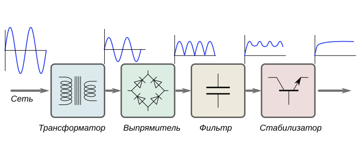
In a linear power supply, the network voltage is lowered (or increased, if necessary) to the required level using a transformer. Next is the rectifier, which converts the alternating voltage into a constant, and the filter, smoothing pulsations. Then there may be a stabilizer that keeps the output voltage constant.
Linear power supplies are gradually replaced by pulsed ones, but the first ones still work in many places. In the microwave, if it is not “inverter”, there is a powerful transformer that raises the mains 220 V to several kilovolts, which are necessary for the operation of the magnetron. Transformers are powered by control electronics in washing machines, stoves and air conditioners. Transformer power supplies are used in audio equipment and cheap chargers.
What happens to a transformer, if it is included in the DC network? First, the voltage does not appear on the secondary windings, since electromagnetic induction occurs only when the current changes. Secondly, the winding will not have inductive resistance, which means that much more current will flow through it than it was calculated. The transformer will overheat and quickly burn out.
Switching power supplies
The higher the frequency of the alternating current, the more efficiently the transformer operates (within reasonable limits, of course). If you use a frequency of several tens of kilohertz instead of the network 50 Hz, you can decently reduce the size of transformers with the same transmitted power. This idea underlies the switching power supplies. Such a unit works as follows: the mains voltage is rectified, the resulting DC voltage feeds the transistor generator, which again gives an alternating voltage, but of high frequency. It can now be lowered or raised by a transformer, straightened and fed into the load.

According to this scheme, the vast majority of electronics are now being powered: computers, monitors, TVs, chargers for laptops, phones and other gadgets. Since the input voltage is first rectified, the switching power supply must operate at a constant current without any problems. But there are a couple of moments that can spoil everything.
First, the voltage after the rectifier is equal to the almost amplitude value of the alternating voltage. That is, for ~ 220 V at the input, the rectifier will give 311 B. By condition, we conditionally supply a constant voltage of 220 V, which is 30% lower. It most likely will not cause problems, because modern power supplies can operate in a wide voltage range, usually from 100 to 250 V.
Secondly, the rectifier consists of four diodes, which operate in pairs: one pair on the positive half-wave of the current, the other on the negative. Thus, each diode transmits current only half the time. If we apply a constant voltage to the rectifier, one pair of diodes will always be open, and double power will be dissipated on them. If the diodes do not have a double current reserve, they can burn out. But this is not too much trouble: you can simply throw out the rectifier and apply a constant voltage immediately after it.
Conclusion
After you put out several fires and raked up the damaged devices, it is time to take stock. The transition to direct current will survive either the old and simple technology (incandescent lamps, heaters, collector motors with mechanical control) or, on the contrary, the most modern (with switching power supplies and inverter motors).
Fortunately, the scenario described is unlikely to materialize in practice unless we consider the possibility of specially organized sabotage. Under no possible accident in the grid, the alternating voltage suddenly becomes constant. True, in case of possible accidents other bad things happen , but that is another story. Take care of yourself and make backups.
Source: https://habr.com/ru/post/372749/
All Articles