Pool Automation with NEVOTON DMC-5.1.1-Z Data Acquisition Module
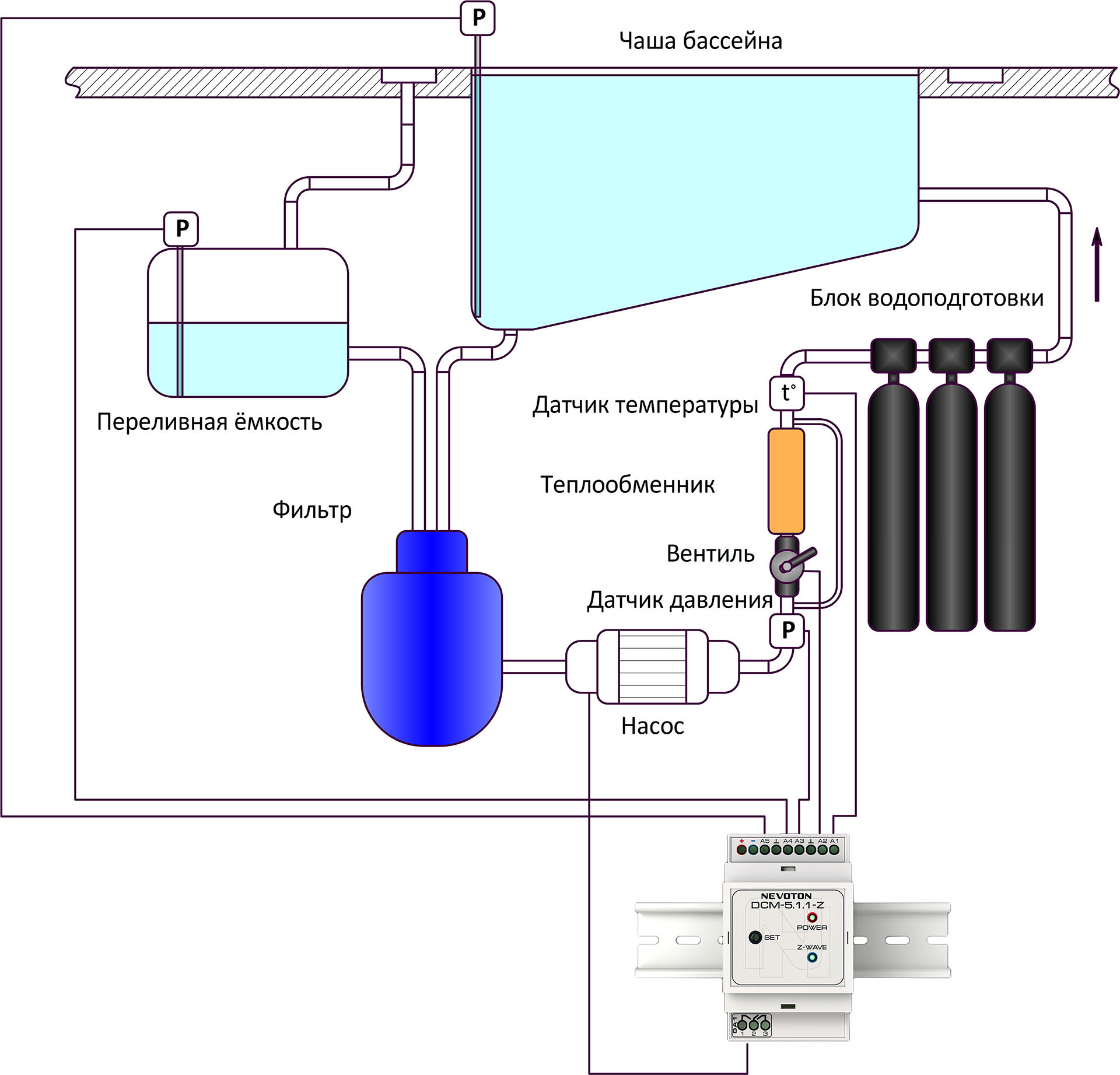
Pic.1 Pool water exchange system
A large distribution in modern suburban construction received private pools with circulating water exchange system. This is a system in which the pump runs continuously and the water circulates continuously in a closed loop, passing successively through the filter, heat exchanger and water treatment system.
The filter mechanically removes water from contamination, the heat exchanger heats the water to a comfortable temperature, the water treatment system provides the necessary concentration of chemically active substances to disinfect water and set the desired pH level.
')
And, if a water treatment system, like any responsible system, is built on already existing specialized controllers, such as, for example, Bayrol Pool Relax, then the rest of the water exchange system is more often passive: the circulating pump runs continuously, the amount of water in the system is not changed or monitored .
At best, install a ball valve, controlled by a thermostat, to maintain the desired water temperature.
This system can be improved using the NEVOTON DCM-5.1.1-Z data acquisition module. It is intended for measuring analog signals from various sensors, transmitting measurement results over a wireless communication network of the Z-Wave standard and switching electrical networks with voltage up to 275 V. Its application will allow the basin water exchange system to be integrated into the home automation system of the Z-Wave standard.
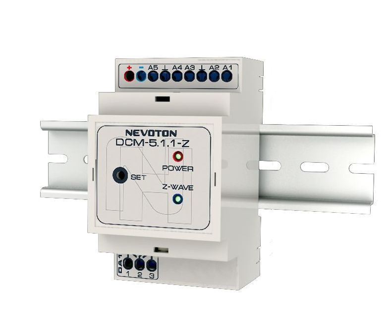
Figure 2. The NEVOTON DCM-5.1.1-Z data acquisition module
It is proposed to measure the following parameters:
- The water pressure in the line after the pump
- Water temperature after heat exchanger
- Water level in the pool
- Water level in the overflow tank, if available in the system
- The position of the ball valve in front of the heat exchanger
It is also possible to control the pump itself (on / off), this reduces the cost of electricity when the pump is running.
It is clear that with prolonged downtime it is possible to pollute the water, surfaces and communications of the basin, but in this case, you can set the scenario of periodic pumping of water, but do not drive water all the time, even if the coming weeks are not going to use the pool.
An example of the inclusion of the data collection module in the pool water exchange system is shown in Fig. 1. The module itself is conveniently located near the pump and the water treatment system. As a rule, they are located in the same room in close proximity to each other.
Since the data acquisition module used is designed to work in a wireless network of the Z-Wave standard, it is necessary to ensure its communication with the automation system controller directly or through intermediate devices of this automation standard.
Configure the NEVOTON DCM-5.1.1-Z I / O module according to the task:
- Water pressure in the line after the pump - pressure sensor with output 0-10 V;
- Water temperature after the heat exchanger - Pt1000 thermal resistance;
- The water level in the pool - a pressure sensor with an output of 0-10 V;
- The water level in the overflow tank, if any, in the system is a pressure sensor with an output of 0-10 V;
- The position of the ball valve in front of the heat exchanger - output 4-20 mA.
Consider the implementation of the proposed solution based on the Raspberry Pi single-board computer with the RaZberry expansion card, designed to work in the Z-Wave network, and installed on the Raspberry Z-Way-server (the installation procedure is described here: razberry.z-wave.me/index.php ? id = 24 ).
Next, follow the instructions here: razberry.z-wave.me/docs/RaZberry500_QSG_en1.pdf , run the Z-Way-server.
The next step is to enable the data collection module in the Z-Wave network. Exclusion and inclusion of the data collection module in the Z-Wave network is performed by pressing the “Set” button located on the front side of the device three times.
If there is no NEVOTON DCM-5.1.1-Z device description file (Description) in your Raspberry, you need to add it.
For this, the NEVOTON DCM-5.1.1-Z.xml file needs to be downloaded from the manufacturer’s website at domoton.ru/shop/modul-sbora-dannyx-dmc-5-1-1-z and added to the / opt / folder z-way-server / ZDDX on your Raspberry Pi.
After that, run the python command ./MakeIndex.py.
Then in Expert UI, select the description file, as shown in Figure. 3

Fig. 3. Select the description file
We will connect the sensors in accordance with the instructions.
Next, enter the tab "Configuration" and configure the type of sensor in all channels.
For Channel 1 (sensor with output voltage 0-10 V):

Fig. 4. Channel 1 configuration for pressure sensor
For Channel 2 (Pt1000 temperature sensor):

Fig. 5. Channel 2 configuration for temperature sensor
For Channel 3 (sensor with output voltage 0-10 V):
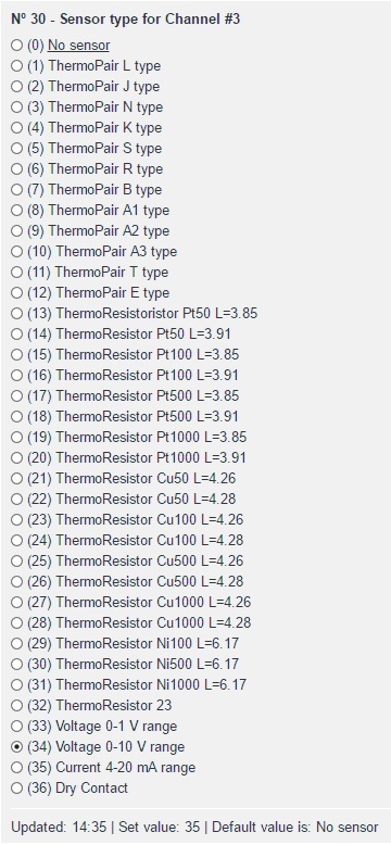
Fig. 6. Channel 3 configuration for pressure sensor
For Channel 4 (sensor with output voltage 0-10 V):
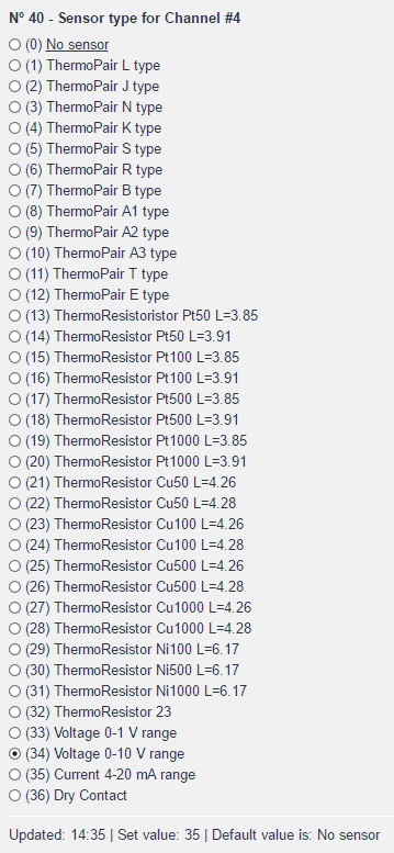
Fig. 7. Channel 4 configuration for pressure sensor
For Channel 5 (sensor with 4-20 mA output current):

Fig. 8. Channel 5 configuration for current sensor
After that, save the configuration, exclude the device from the network and turn it on again.
The device involves the use of an internal relay if necessary, as shown in Fig. 9.
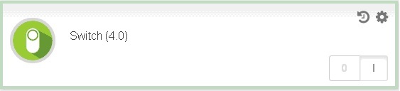
Fig. 9. Status and on / off relay
After the inputs are configured, the NEVOTON DCM-5.1.1-Z will begin to measure the sensor outputs, and the results are shown in fig. ten.
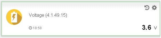
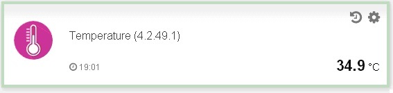
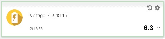


Fig. 10. Sensor readings in Smarthome GUI (v. 2.2)
In order to normalize sensor data and display it in a user-friendly form, you can use the DataSensorMultiplication module, which can also be downloaded from the manufacturer’s website at domoton.ru/shop/modul-sbora-dannyx-dmc-5-1-1 -z . The module after installation has the name “Physical conversion module” - in the English interface and “Module for the conversion of physical quantities” - in the Russian-language interface.
This module converts the sensor reading into any physical quantity using the formula (Sensor Value * Multiplier) with the display of the desired name of the physical quantity.
After downloading, the module must be unpacked and added to the / opt / z-way-server / automation / modules folder on Raspberry. Next, you need to restart the server with sudo service z-way-server restart. After that, the module will be available for use.
For example, it is known that to bring the values of the pressure sensor with an output of 0-10 V (Channel 1, the water pressure in the line after the pump) to 1 atm, the sensor value must be multiplied by 0.785. To do this, configure the module, as shown in Fig. eleven.

Fig. 11. Configure the value conversion module
The result of the module is shown in Fig. 12.

Fig. 12. The result of the conversion module
This module can be used as often as desired, and each time a virtual device will be created with fields for display. Values from this virtual device can be used in further scenarios of Smart Home automation.
Thus, it is always possible, for convenience of perception, to convert data from sensors into any type (recalculate readings according to the level of liquid in any geometric volume, etc., i.e., it is important to calculate the coefficient and set it in the module).
By coupon GT_NEVOTON in the store 5smart.ru discount of all 10%!
Source: https://habr.com/ru/post/372501/
All Articles