Mechanical model of electrical circuits
Here you can even model a transformer and an operational amplifier, but in order.
Electrical circuits can be described by the following equations:
(The voltage drop on the coil is equal to minus the EMF)
')
In mechanics there are the following equations:
(The external force acting on the spring is equal to minus the force on the side of the spring, if there is no mass at the point of application of force)
As you probably guessed, electrical and mechanical quantities can be compared in two ways:
Usually, when they try to draw an electro-mechanical analogy, they use the first method, although in some places you can come across the second one, which we will use.
But we will simulate in rotational mechanics, where we will replace each translational quantity with the corresponding moment or angular value:
But for simplicity, we will denote as in translational mechanics:
Since there is a potential in electricity (at a point) and voltage (between points), we will simulate the potential by the speed of rotation of the shaft, and the voltage by the difference of the speeds of the two shafts. It can be obtained using a differential (like in a car), in which one of the side shafts is inverted:

Above, extensive theoretical considerations have been set forth why we will do just that. Next will be described directly how we will do it.
It can be simulated as a shaft rotating at a constant speed (which is not impossible to stop), and connected to a differential differential input. With the other two of its ends, you can relieve tension (they spin relative to each other at a constant speed).
The same, but only used shaft, issuing a constant torque. Such a shaft without load will accelerate to an infinitely high speed of rotation.
From the differential are the blades and descend into the glass with the liquid.

The more viscous the liquid, the more conductivity, the less resistance. Between unconnected shafts endless resistance. And the resistor, which has jammed blades, has zero resistance. You can dream up about the breakdown voltage, and the friction between the shaft and its holders, but in my opinion this similarity is somehow not very.

As in the ideal capacitor, there is no leakage current, and also in its model there is no friction at all. Just as the current charges the capacitor, so the moment of forces between the shafts accelerates the flywheel. In such a capacitor on one plate is always a charge , and on the other -
  .
.
Also, a single sphere (or another form of conductor) may have capacity. If it is charged with charge Q, then there will be a potential on its surface. . Their attitude will be the capacity of this conductor. This can be modeled with a flywheel without differential.
("Grounding" will denote the fixed parts of the structure)
Where v is the speed difference between two shafts, and x is their relative displacement.
If we assume that the spring stiffness is large enough, and the moment of forces transmitted from one shaft to another is small enough, then the coil can be modeled as follows:
If we fantasize, then we can draw an analogy between the hysteresis loop of ferromagnetic and inelastic deformation of the spring. True in ferromagnets there is no analogue of metal fatigue.
And also, the coil model can be used as an ammeter model, if you attach the arrow to the output of the differential.
Its direction of deviation from the equilibrium position will indicate in which direction the shaft number 1 pushes the shaft number 2. And its value is about the moment of forces with which one shaft acts on another, i.e. about the strength of the current through the simulated coil.
And from the seemingly simplest law it turns out that minus [EMF of the coil] = [voltage of the fall on it] = velocity difference of the shafts = time derivative of the relative displacement of two shafts. In the coil, which is not connected to anything always current = 0, and in its model, the spring is not deformed. But if there is a current in the coil, and then it is short-circuited (by a superconductor), then the current in it will remain, and its model will remain in the deformed state.
In principle, in the coil you can do without the differential, but in the transformer, which contains a pair of coils, it will not work.

Initially, the capacitor is not charged.
Turn on the key (after that ), and the supply voltage is on the resistor, current flows through it and the capacitor charges, which is equivalent to the fact that the voltage starts to rise on the capacitor, and the voltage drops on the resistor, respectively, and the current, respectively, also starts to fall. If after some time the key is opened, the capacitor will remain charged, and the voltage across the resistor will drop to 0.
Initially the flywheel is resting.
We turn on the key (after that the sum of the flywheel speeds and the resistor blades is equal to the speed of the voltage source), the flywheel is at rest at the initial moment, and the resistor blades (weightless) start to rotate, but due to friction, a moment of forces arises that accelerates the flywheel. The faster the flywheel turns, the slower the blades of the resistor spin, and the less force the flywheel rotates. If after some time the key is unlocked, the flywheel will continue to rotate without changing its speed, and the speed of the resistor blades will drop to 0.
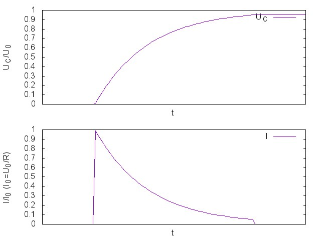
Initially, the current is zero. We turn on the key (after that ), and the supply voltage is applied to the coil, and it begins to gradually accelerate the current through the coil. As the current increases, the voltage drops across the resistor, which means the voltage that accelerates the current in the coil decreases, which means that the current gradually stops growing. If after some time the key is opened, then as a result of an almost instantaneous stopping of the current on the coil there will be a very short burst of EMF, the polarity of which will be inverse to the polarity of the voltage source.
At first, the spring is not stretched. We turn on the key (after that the sum of the deformation speeds of the spring and the blades of the resistor is equal to the speed of the voltage source), and the spring begins to stretch as if at the very initial moment of the resistor = 0. An already stretched spring begins to exert force on the resistor, as a result of which a velocity difference arises in the resistor, and in a spring the velocity difference begins to decrease. The more the spring is stretched, the more force it has on the resistor, the greater the speed difference in the resistor, and the smaller the speed difference in the coil (or rather in its model), and the slower the coil spring stretches further. If after some time the key is unlocked, then as a result of the almost instantaneous fall of the load on the spring, it will quickly contract to its original position.
The mechanical model can be simplified by imagining a weightless boat resting on the water, to which a spring is attached, and the other end of the spring suddenly begins to pull at a constant speed. Initially, the boat is resting. Then the spring begins to stretch, and the more it stretches, the more it carries along the boat, and the smaller the difference between the speeds of the two ends of the spring. And if the spring is released (the mass of the boat and the mass of the spring = 0), then the boat will immediately stop, and the spring will immediately contract.

The transformer itself is also described as a coil:

Where
In other words, a transformer is described by a system of equations:
%0A)
And in order to get a mechanical model of a transformer, it is enough to take mechanical models of two coils, and connect them with a spring through a lever:
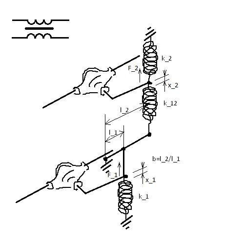
It is possible to replace all translational springs with rotational ones and replace the lever with a gearbox:

We find the equations describing this system.
Suppose the lower shoulder has shifted up to (at the spring attachment point) by force
  and the top has shifted up on
  (at the spring attachment point) by force
  . Writing the second laws of Newton for both weightless arms coming from differentials, we get the system:
%5C%5C%0AF_2%3Dk_2%20x_2%2Bk_%7B12%7D(x_2-bx_1)%0A%5Cend%7Bcases%7D%0A)
which is the same with
x_1-bk_%7B12%7Dx_2%5C%5C%0AF_2%3D-bk_%7B12%7Dx_1%2B(k_2%2Bk_%7B12%7D)x_2%0A%5Cend%7Bcases%7D%0A)
it can be resolved relatively and :

Where))
Comparing this system with (1) it turns out that the matrix

should be matched with the matrix
%7D%0A)
And if we have a transformer, in which all the turns are identical in shape and section, on the 1st winding turns, on the second -
  and
and  - the fraction of the magnetic flux generated by the 1st coil, which passes through the 2nd coil (or vice versa - they coincide) (If the coils are at a great distance, then
  and these are actually two different coils. And if the coils are close to each other and also connected by a core, then
  .), then the inductance matrix will look like this:

Where - coefficient depending on the size of the transformer and the core material.
If you take in his model , then from ratios

the spring stiffness relationship will look like this:
)


and the inductance matrix of the model is:
![[L] = \ begin {pmatrix} (k_2 + k_ {12}) / b ^ 2 & amp; k_ {12} / b \\ k_ {12} / b & amp; k_2 + k_ {12} \ end {pmatrix} \ frac {1} {k_2 ^ 2 + 2k_ {12} k_2}](https://tex.s2cms.ru/svg/%5BL%5D%20%3D%20%0A%5Cbegin%7Bpmatrix%7D%0A(k_2%2Bk_%7B12%7D)%2Fb%5E2%20%20%20%20%26%20k_%7B12%7D%2Fb%20%20%5C%5C%0Ak_%7B12%7D%2Fb%20%20%20%20%20%20%20%20%26%20k_2%2Bk_%7B12%7D%20%20%20%20%0A%5Cend%7Bpmatrix%7D%0A%5Cfrac%7B1%7D%7Bk_2%5E2%2B2k_%7B12%7Dk_2%7D%0A)
because![c \ in [0..1]](https://tex.s2cms.ru/svg/c%20%5Cin%20%5B0..1%5D) then
then  =>
=> 
then the stiffness ratios are also> 0 (if we exclude a lever from the model, ie, b = 1, then one of these ratios will be negative, and there are no springs with negative stiffness).
And back: with any ratio of spring stiffness


and at any ratio of the arms of the lever b> 0
![c = \ frac {1} {\ sqrt {1 + a_1 / b ^ 2 + a_2 + a_1a_2 / b ^ 2}} \ in [0..1]](https://tex.s2cms.ru/svg/c%3D%5Cfrac%7B1%7D%7B%5Csqrt%7B1%2Ba_1%2Fb%5E2%20%2Ba_2%2Ba_1a_2%2Fb%5E2%7D%7D%20%5Cin%20%5B0..1%5D)
%20%3D%20(1%2Ba_2)%2Fb)
%20%3D%20(1%2Bb%5E2a_1)%2Fb)
With
 and coil models become almost independent.
With
 and models of coils are rigidly connected through a lever without a spring. And inductances start tending to
![[L_ {11}] = \ frac {k_2 + k_ {12}} {b ^ 2 (k_2 ^ 2 + 2k_ {12} k_2)} \ to \ frac {1} {2b ^ 2k_2} = \ frac {1 } {2k_1}](https://tex.s2cms.ru/svg/%5BL_%7B11%7D%5D%3D%5Cfrac%7Bk_2%2Bk_%7B12%7D%7D%7Bb%5E2(k_2%5E2%2B2k_%7B12%7Dk_2)%7D%5Cto%20%5Cfrac%7B1%7D%7B2b%5E2k_2%7D%3D%5Cfrac%7B1%7D%7B2k_1%7D)
![[L] \ to \ frac {1} {2} \ begin {pmatrix} 1 / k_1 & amp; 1 / bk_2 \\ 1 / bk_2 & amp; 1 / k_2 \ end {pmatrix}](https://tex.s2cms.ru/svg/%5BL%5D%5Cto%0A%5Cfrac%7B1%7D%7B2%7D%0A%5Cbegin%7Bpmatrix%7D%0A1%2Fk_1%20%20%20%26%201%2Fbk_2%5C%5C%0A1%2Fbk_2%20%20%26%201%2Fk_2%0A%5Cend%7Bpmatrix%7D%0A)
and calculate it

->

let be

%7D%0A)
then

the last equation can be rewritten as

OPOC:
%7D%3E0)
This contribution will be visible only immediately after switching on the scheme, then it will attenuate and will not participate in the steady state transformation.
If you change the equation like this:

and look for CHRNS in the form then we come to the algebraic equation

=>
%5E2%7D%7D)
%20%3D%20%5Cfrac%7B%5Comega%7D%7BM_%7B22%7DR_2%7D)
because then
then
%5E2%7D%7D%0A%5Ccos(%5Comega%20t-arctg%20%5Cfrac%7B%5Comega%7D%7BM_%7B22%7DR_2%7D)%3D)
![= \ frac {-cU_0} {\ sqrt {\ omega ^ 2 \ frac {N_1 ^ 2N_2 ^ 2} {L_0} (1-c ^ 2) + \ frac {N_1 ^ 2} {N_2 ^ 2} R_2 ^ 2 }} \ cos (\ omega t-arctg \ frac {\ omega N_2 ^ 2 (1-c ^ 2) L_0} {R_2}) \ xrightarrow [c \ to 1] {}](https://tex.s2cms.ru/svg/%3D%5Cfrac%7B-cU_0%7D%7B%5Csqrt%7B%5Comega%5E2%5Cfrac%7BN_1%5E2N_2%5E2%7D%7BL_0%7D(1-c%5E2)%2B%5Cfrac%7BN_1%5E2%7D%7BN_2%5E2%7DR_2%5E2%7D%7D%5Ccos(%5Comega%20t-arctg%5Cfrac%7B%5Comega%20N_2%5E2(1-c%5E2)L_0%7D%7BR_2%7D)%5Cxrightarrow%5Bc%5Cto%201%5D%7B%7D)
![\ xrightarrow [c \ to 1] {} - \ frac {N_2} {N_1} \ frac {U_0 \ cos \ omega t} {R_2}](https://tex.s2cms.ru/svg/%5Cxrightarrow%5Bc%5Cto%201%5D%7B%7D%20-%5Cfrac%7BN_2%7D%7BN_1%7D%5Cfrac%7BU_0%5Ccos%20%5Comega%20t%7D%7BR_2%7D)
In the case of a mechanical model of this scheme
![[I_2] = \ frac {-b [U_0]} {\ sqrt {\ frac {\ omega ^ 2} {k_ {12} ^ 2} + (\ frac {k_2} {k_ {12}} + 1) ^ 2 [R_2] ^ 2}} \ cos (\ omega t-arctg \ frac {\ omega} {(k_2 + k_ {12}) [R_2]}) \ xrightarrow [k_ {12} \ to \ infty] {} \ frac {-b [U_0] \ cos \ omega t} {[R_2]}](https://tex.s2cms.ru/svg/%5BI_2%5D%3D%5Cfrac%7B-b%5BU_0%5D%7D%7B%5Csqrt%7B%5Cfrac%7B%5Comega%5E2%7D%7Bk_%7B12%7D%5E2%7D%2B(%5Cfrac%7Bk_2%7D%7Bk_%7B12%7D%7D%2B1)%5E2%5BR_2%5D%5E2%7D%7D%5Ccos(%5Comega%20t-arctg%5Cfrac%7B%5Comega%7D%7B(k_2%2Bk_%7B12%7D)%5BR_2%5D%7D)%5Cxrightarrow%5Bk_%7B12%7D%5Cto%20%5Cinfty%5D%7B%7D%20%5Cfrac%7B-b%5BU_0%5D%5Ccos%20%5Comega%20t%7D%7B%5BR_2%5D%7D)
where the values in square brackets should be replaced by their mechanical counterparts.
As expected, the stiffness of the first spring does not play any role (for any c).
If we simplify the mechanical analogue of this scheme, then we will have a weightless ship on the water, tied to the shore through a spring, and which through another spring and lever move back and forth according to the harmonic law.

The diode can be modeled using nonlinear elements, an operational amplifier (which works like this: if the input voltage is + more than the input voltage is, it gives out + U, and if it is the other way around, then -U) as in the picture, and the transistor is me I did not think how.

In models of resistor, diode and single coil, you can do without the differential. If we fantasize, the friction of the shafts in the mountings can be interpreted as the leakage current through the wire insulator, the deformation of the shafts as the parasitic inductance of the wires, and the inertia moment of the shafts as the parasitic capacitance. But the wire models do not contain resistance in themselves - they are superconducting.
It would be fun if someone in reality did something like that (for example from a lego-technician, or printed it on a 3d printer), and laid it out on YouTube.
Electrical circuits can be described by the following equations:
for coil
for condenser
for resistor
(The voltage drop on the coil is equal to minus the EMF)
')
In mechanics there are the following equations:
for massive body
for spring
for viscous friction
(The external force acting on the spring is equal to minus the force on the side of the spring, if there is no mass at the point of application of force)
As you probably guessed, electrical and mechanical quantities can be compared in two ways:
| electro | mech.1 | mech.2 |
|---|---|---|
| U | F | v |
| I | v | F |
| F | p | x |
| Q | x | p |
| L | m | 1 / k |
| C | 1 / k | m |
| R |
Usually, when they try to draw an electro-mechanical analogy, they use the first method, although in some places you can come across the second one, which we will use.
But we will simulate in rotational mechanics, where we will replace each translational quantity with the corresponding moment or angular value:
where
- angular stiffness
where
- angular viscosity
But for simplicity, we will denote as in translational mechanics:
- voltage
- shaft rotation speed
- current strength
- the moment of forces arising in the shaft
- magnetic flux through the coil
- angular deformation of the spring
- capacitor charge
- flywheel momentum
- coil inductance
- reverse angular stiffness of the spring
- capacitor capacitance
- the moment of inertia of the flywheel
- resistor resistance
- inverse angular coefficient of viscous friction of something in something
Since there is a potential in electricity (at a point) and voltage (between points), we will simulate the potential by the speed of rotation of the shaft, and the voltage by the difference of the speeds of the two shafts. It can be obtained using a differential (like in a car), in which one of the side shafts is inverted:
Above, extensive theoretical considerations have been set forth why we will do just that. Next will be described directly how we will do it.
Let us turn to the modeling of electrical components:
Voltage source
It can be simulated as a shaft rotating at a constant speed (which is not impossible to stop), and connected to a differential differential input. With the other two of its ends, you can relieve tension (they spin relative to each other at a constant speed).
Current source
The same, but only used shaft, issuing a constant torque. Such a shaft without load will accelerate to an infinitely high speed of rotation.
I would model the resistor like this:
From the differential are the blades and descend into the glass with the liquid.
The more viscous the liquid, the more conductivity, the less resistance. Between unconnected shafts endless resistance. And the resistor, which has jammed blades, has zero resistance. You can dream up about the breakdown voltage, and the friction between the shaft and its holders, but in my opinion this similarity is somehow not very.
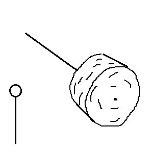
Condenser - flywheel attached to differential
As in the ideal capacitor, there is no leakage current, and also in its model there is no friction at all. Just as the current charges the capacitor, so the moment of forces between the shafts accelerates the flywheel. In such a capacitor on one plate is always a charge
Also, a single sphere (or another form of conductor) may have capacity. If it is charged with charge Q, then there will be a potential on its surface.
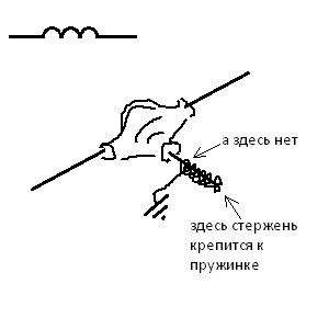
Coil - spring attached to the differential
("Grounding" will denote the fixed parts of the structure)
Where v is the speed difference between two shafts, and x is their relative displacement.
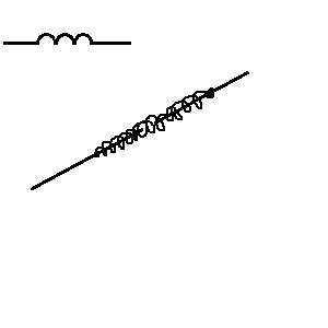
If we assume that the spring stiffness is large enough, and the moment of forces transmitted from one shaft to another is small enough, then the coil can be modeled as follows:
If we fantasize, then we can draw an analogy between the hysteresis loop of ferromagnetic and inelastic deformation of the spring. True in ferromagnets there is no analogue of metal fatigue.
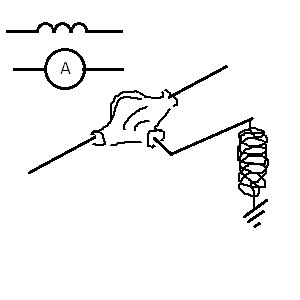
And also, the coil model can be used as an ammeter model, if you attach the arrow to the output of the differential.
Its direction of deviation from the equilibrium position will indicate in which direction the shaft number 1 pushes the shaft number 2. And its value is about the moment of forces with which one shaft acts on another, i.e. about the strength of the current through the simulated coil.
And from the seemingly simplest law
In principle, in the coil you can do without the differential, but in the transformer, which contains a pair of coils, it will not work.
Consider a couple of transients.
Voltage source, switch, resistor, (initially uncharged) capacitor.
Initially, the capacitor is not charged.
Turn on the key (after that
Initially the flywheel is resting.
We turn on the key (after that the sum of the flywheel speeds and the resistor blades is equal to the speed of the voltage source), the flywheel is at rest at the initial moment, and the resistor blades (weightless) start to rotate, but due to friction, a moment of forces arises that accelerates the flywheel. The faster the flywheel turns, the slower the blades of the resistor spin, and the less force the flywheel rotates. If after some time the key is unlocked, the flywheel will continue to rotate without changing its speed, and the speed of the resistor blades will drop to 0.
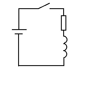
Voltage source, switch, resistor, coil.
Initially, the current is zero. We turn on the key (after that
At first, the spring is not stretched. We turn on the key (after that the sum of the deformation speeds of the spring and the blades of the resistor is equal to the speed of the voltage source), and the spring begins to stretch as if at the very initial moment of the resistor = 0. An already stretched spring begins to exert force on the resistor, as a result of which a velocity difference arises in the resistor, and in a spring the velocity difference begins to decrease. The more the spring is stretched, the more force it has on the resistor, the greater the speed difference in the resistor, and the smaller the speed difference in the coil (or rather in its model), and the slower the coil spring stretches further. If after some time the key is unlocked, then as a result of the almost instantaneous fall of the load on the spring, it will quickly contract to its original position.
The mechanical model can be simplified by imagining a weightless boat resting on the water, to which a spring is attached, and the other end of the spring suddenly begins to pull at a constant speed. Initially, the boat is resting. Then the spring begins to stretch, and the more it stretches, the more it carries along the boat, and the smaller the difference between the speeds of the two ends of the spring. And if the spring is released (the mass of the boat and the mass of the spring = 0), then the boat will immediately stop, and the spring will immediately contract.
And finally, the mechanical model of the transformer.
The transformer itself is also described as a coil:
Where
- U - stress column
and
on 1st and 2nd coils.
- - column of magnetic fluxes.
and
through 1st and 2nd coil.
- I - current column
and
through 1st and 2nd coil.
- L - symmetric (
) mutual inductance matrix
between the respective coils.
In other words, a transformer is described by a system of equations:
And in order to get a mechanical model of a transformer, it is enough to take mechanical models of two coils, and connect them with a spring through a lever:
It is possible to replace all translational springs with rotational ones and replace the lever with a gearbox:
We find the equations describing this system.
Suppose the lower shoulder has shifted up to
which is the same with
it can be resolved relatively
Where
Comparing this system with (1) it turns out that the matrix
should be matched with the matrix
And if we have a transformer, in which all the turns are identical in shape and section, on the 1st winding
Where
If you take in his model
the spring stiffness relationship will look like this:
and the inductance matrix of the model is:
because
then the stiffness ratios are also> 0 (if we exclude a lever from the model, ie, b = 1, then one of these ratios will be negative, and there are no springs with negative stiffness).
And back: with any ratio of spring stiffness
and at any ratio of the arms of the lever b> 0
With
With
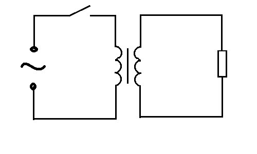
For an example of the operation of a transformer, consider the circuit: an alternating voltage source, a transformer, a resistor
and calculate it
->
let be
then
the last equation can be rewritten as
OPOC:
This contribution will be visible only immediately after switching on the scheme, then it will attenuate and will not participate in the steady state transformation.
If you change the equation like this:
and look for CHRNS in the form
=>
because
In the case of a mechanical model of this scheme
where the values in square brackets should be replaced by their mechanical counterparts.
As expected, the stiffness of the first spring does not play any role (for any c).
If we simplify the mechanical analogue of this scheme, then we will have a weightless ship on the water, tied to the shore through a spring, and which through another spring and lever move back and forth according to the harmonic law.
Nonlinear elements
The diode can be modeled using nonlinear elements, an operational amplifier (which works like this: if the input voltage is + more than the input voltage is, it gives out + U, and if it is the other way around, then -U) as in the picture, and the transistor is me I did not think how.
Instead of conclusion
In models of resistor, diode and single coil, you can do without the differential. If we fantasize, the friction of the shafts in the mountings can be interpreted as the leakage current through the wire insulator, the deformation of the shafts as the parasitic inductance of the wires, and the inertia moment of the shafts as the parasitic capacitance. But the wire models do not contain resistance in themselves - they are superconducting.
It would be fun if someone in reality did something like that (for example from a lego-technician, or printed it on a 3d printer), and laid it out on YouTube.
Source: https://habr.com/ru/post/372403/
All Articles