Autonomous quadcopter 280mm for shooting from the air
Hello to all! I want to talk about the creation of a small Copter that can fly independently, without mediocre control through radio equipment, and at the same time carry out shooting. The idea originated before another trip to Asia. I wanted to take a copter with me and take pictures of it, but at the same time drag a minimum of electronics and components, and also to have the copter itself take up very little space.
At once I want to present the result of this venture - the captured video, and below describe what components of the kopter is assembled, how it is set up and what difficulties it had to face when operating this device.
')
Frame construction and electronics.
Immediately came the idea that you can assemble a drone on the base of the frame for FPV Racer. It was just such a thing that lay idle so far, because because of the snow in winter, the FPV did not particularly want to fly.

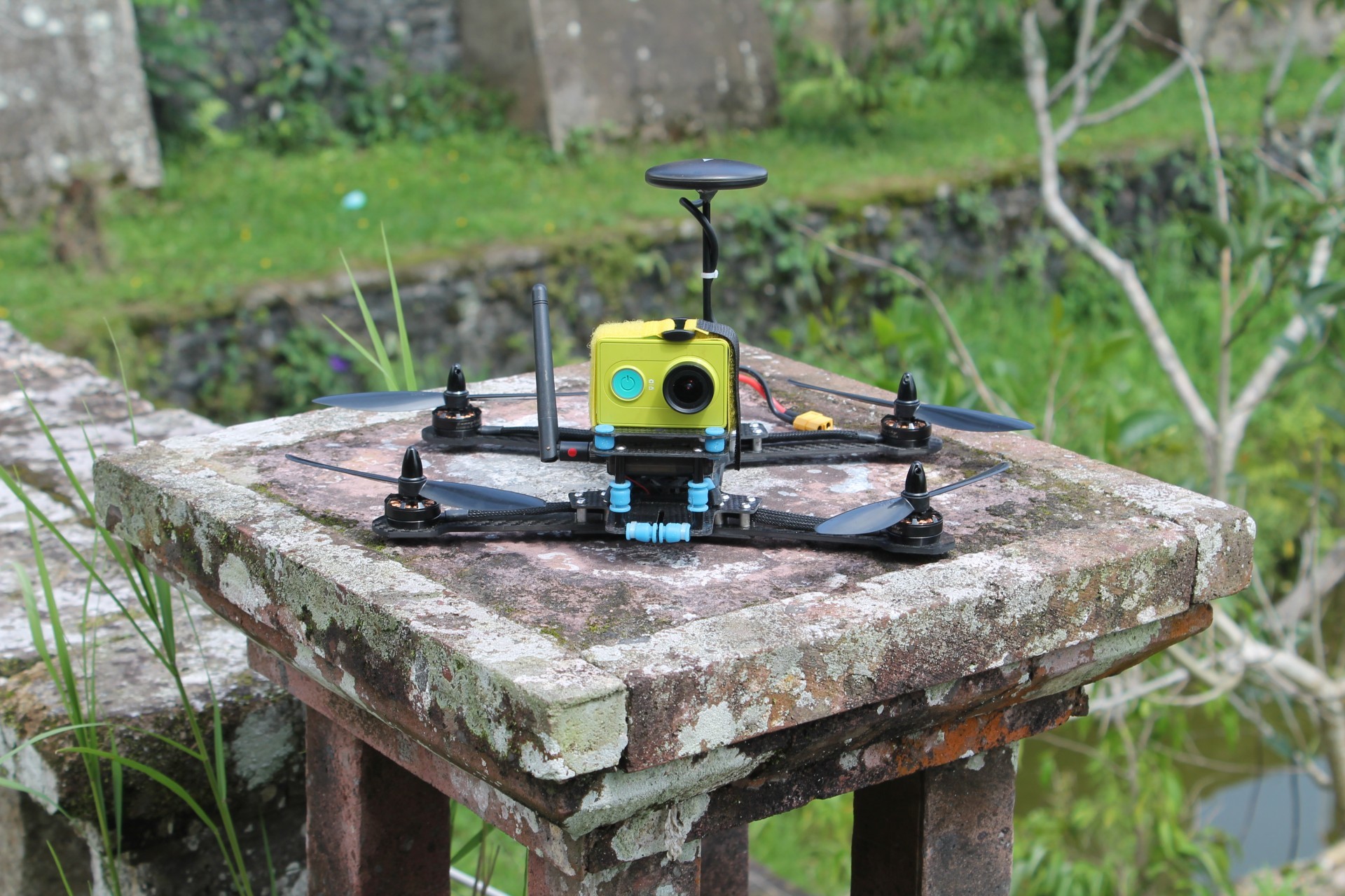
The frame is cut out of carbon with small modifications to this frame . The changes are in the mounting holes for the motors and the shape of the damping platform for the Xaiom Yi camera, instead of Mobius. The screws are chosen 6045, since it is clear from the characteristics of the motor that they are most effective. The flight time with a battery of 3s 2200 mAh is 10-11 minutes.

Engine controllers are installed DYS SN20A . They are inexpensive and fairly reliable, especially for unhurried automatic control.
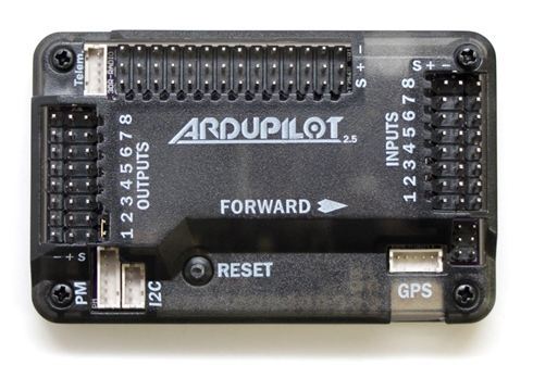
The main element of the electronics - flight controller or autopilot - selected 3DR APM 2.5 . In fact, it is already outdated, but was at hand. Of course, if you can, it’s better to use Pixhawk. ArduCopter firmware for APM is not supported from version 3.2.1, although it contains everything you need to cope with the tasks.
To improve the quality of control of the flight controller, vibration isolation with a frame is needed (to reduce noise on the accelerometer and gyroscope), so the autopilot is installed on the damping platform . In my case, it is printed on a 3d printer, but other designs can also be considered . The barometer built into the autopilot is used to measure altitude, and an accelerometer, gyroscope and magnetometer are used to determine the angular position. It is better to use an external magnetometer in order to reduce the negative impact of metal parts and power electronics on the magnetic field.
Now consider the important part for autonomous flight - this is a GPS module, which also has a magnetometer. The module is necessary for positioning in the horizontal plane to fly on a given route. The module is brought up 12cm upwards to improve the accuracy of measurements of the magnetometer, in addition the reception of GPS signals is better if the upper hemisphere of the antenna, which is also located on the module, is completely open. I used Ublox Neo-M8N . The module had to unscrew one of the three iron screws on the case (in the photo on the left), since it was located near the magnetometer chip.

To send commands from the ground and receive telemetry from the kopter, radio communication is necessary. A good choice is SiK Telemetry Radio modems. The version 900 MHz is installed on the copter. In a city, such a connection is enough for 500-700 meters without direct visibility. Thanks to modems, you can send a compiled flight mission to a kopter (see below), give a command to take off or return home (if it is clear that something went wrong), change the autopilot parameters and much more. Also, from the drone to the ground, you can get information about the location, altitude, battery charge, etc. In general, the communication range is not so important, since during long-distance flights the kopter moves independently according to the mission previously recorded in it. The interruption of communication is bad because the drone cannot be returned home at any time, and it is also not clear at what point on the map to look for it in the event of a fall.
To connect the modem to the smartphone, you need a USB OTG cable. The most convenient way to use a model with two angled microUSB. I made it myself, but you can buy a cable from 3DR. The modem is attached to the phone with a sticky tape.

There is also a power module on the copter that converts the battery voltage (3s, 11.1 V) to the power supply voltage of the control electronics (5 V). The power board is equipped with a current and voltage sensor to monitor the battery charge.

Since before the autonomous flight of the kopter it is necessary to adjust (the coefficients of the PID-regulators and other parameters of the autopilot), at the initial stage a radio receiver was installed to control the equipment. This allows you to manually control the copter to debug the stability of the flight and land it in case of unforeseen situations.
For shooting, the camera is used Xiaomi Yi , since it is the most optimal in price and quality. It is installed on the frame through rubber dampers to reduce the effect of vibrations on video quality.

Setting up the flight controller and the first flights.
Since self-assembled copters consist of a unique set of a screw-motor group, speed regulators, a frame, an accumulator and an additional load, and they can also be designed for various purposes, it is necessary to tune the flight controller in a certain way. The most functional shell for configuring the ArduCopter is MissionPlanner for Windows.
Let's start with PID controllers. Stable and stable flight ensures the selection of coefficients of the controller components. You can read more on the official website ArduCopter. The most important are the contours of control in roll and pitch. The easiest way to do this is using the remote control, changing coefficients and observing changes in flight. In Stabilize mode, it is necessary to achieve the most responsive control of roll, pitch and lynx without oscillations.
Then go to the Alt Hold - the altitude hold mode, in which the barometer is activated. It is worth paying attention to the parameter INAV_TC_Z . It was raised to 6 in order to avoid loss of height when starting to move from a point of hang.
When everything is fine with the altitude hold, it remains to check the flight mode by GPS - Loiter . Before starting the tests it is necessary to calibrate the compass (magnetometer). Most accurately this can be done on the street, away from metal structures. Calibration eliminates local (located on the copter) distortion of the magnetic field. Then you can check how the drone behaves when flying with GPS positioning. Do not forget about the number of satellites and the HDOP parameter, if they are lower than the default, then you can forget about a stable flight. Launches can be made at a distance from tall buildings and trees that can block GPS signals. Also, a negative impact on the compass is made by iron objects, which can introduce distortions in readings and lead to incorrect behavior in flight. Loiter PID parameters can be left as default.
The main goal is autonomous flight. It is represented by Auto mode, and its associated RTL , Guided and Follow Me . If the first three modes described above are properly configured, then Auto should not have any problems. Speaking about the parameters of the automatic modes, you can pay attention to RTL_ALT (height when returning to the starting point), WPNAV_RADIUS (the radius with which the rotor will cut off the corners of the route), WPNAV_LOIT_SPEED, WPNAV_SPEED_DN, WPNAV_SPEED_UP (horizontal and vertical speeds), Zeyyyyyyyyyyyyyyyyyyyyyyyyyyyyyyyyyyyyyyyyyyyyyyyyyyyyyyyyyyyyyyyyyyyyyyyyyyyyyyyyyyyyyyyyyyyyyyyyyyyyyyyyyyyyyyyyyyyyyyyyyyyyyyyyyyyyyyyyyyyyyyyyyyyyyyyyyyyyyyyyyyyyyyyyy_d). "Watch" the kopter when driving on the route).
All parameters can be viewed below. I note that if you assemble the same configuration on the kopter, you can skip the configuration step, and simply fill in the existing parameters in the autopilot. You can even not use the remote and the receiver to debug, but this is at your own risk.
Parameters AP
ACRO_BAL_PITCH,1.00000000 ACRO_BAL_ROLL,1.00000000 ACRO_EXPO,0.30000001 ACRO_RP_P,4.50000000 ACRO_TRAINER,2 ACRO_YAW_P,4.50000000 AHRS_COMP_BETA,0.10000000 AHRS_GPS_GAIN,1.00000000 AHRS_GPS_MINSATS,6 AHRS_GPS_USE,1 AHRS_ORIENTATION,0 AHRS_RP_P,0.10000000 AHRS_TRIM_X,0.00480902 AHRS_TRIM_Y,0.00000000 AHRS_TRIM_Z,0.00000000 AHRS_WIND_MAX,0 AHRS_YAW_P,0.10000000 ANGLE_MAX,4500 ARMING_CHECK,1 ATC_ACCEL_RP_MAX,0.00000000 ATC_ACCEL_Y_MAX,0.00000000 ATC_RATE_FF_ENAB,0 ATC_RATE_RP_MAX,18000.00000000 ATC_RATE_Y_MAX,9000.00000000 ATC_SLEW_YAW,1000.00000000 BAROGLTCH_ACCEL,1500.00000000 BAROGLTCH_DIST,500.00000000 BAROGLTCH_ENABLE,1 BATT_AMP_OFFSET,0.00000000 BATT_AMP_PERVOLT,18.00000000 BATT_CAPACITY,1400 BATT_CURR_PIN,12 BATT_MONITOR,4 BATT_VOLT2_MULT,1.00000000 BATT_VOLT2_PIN,-1 BATT_VOLT_MULT,10.01000023 BATT_VOLT_PIN,13 CAM_DURATION,10 CAM_SERVO_OFF,1100 CAM_SERVO_ON,1300 CAM_TRIGG_DIST,0.00000000 CAM_TRIGG_TYPE,0 CH7_OPT,4 CH8_OPT,0 CIRCLE_RADIUS,1000.00000000 CIRCLE_RATE,20.00000000 COMPASS_AUTODEC,1 COMPASS_DEC,0.00000000 COMPASS_EXTERNAL,0 COMPASS_LEARN,0 COMPASS_MOTCT,0 COMPASS_MOT_X,0.00000000 COMPASS_MOT_Y,0.00000000 COMPASS_MOT_Z,0.00000000 COMPASS_OFS_X,-40.00000000 COMPASS_OFS_Y,-4.00000000 COMPASS_OFS_Z,-27.00000000 COMPASS_ORIENT,8 COMPASS_USE,1 DCM_CHECK_THRESH,0.80000001 EKF_CHECK_THRESH,0.80000001 ESC,0 FENCE_ACTION,1 FENCE_ALT_MAX,100.00000000 FENCE_ENABLE,0 FENCE_MARGIN,2.00000000 FENCE_RADIUS,300.00000000 FENCE_TYPE,3 FLOW_ENABLE,0 FLTMODE1,0 FLTMODE2,0 FLTMODE3,0 FLTMODE4,2 FLTMODE5,0 FLTMODE6,5 FRAME,1 FS_BATT_ENABLE,0 FS_BATT_MAH,0.00000000 FS_BATT_VOLTAGE,10.50000000 FS_GCS_ENABLE,1 FS_GPS_ENABLE,1 FS_THR_ENABLE,0 FS_THR_VALUE,975 GND_ABS_PRESS,99934.92968750 GND_ALT_OFFSET,0 GND_TEMP,20.61724091 GPSGLITCH_ACCEL,1000.00000000 GPSGLITCH_ENABLE,1 GPSGLITCH_RADIUS,200.00000000 GPS_HDOP_GOOD,230 GPS_NAVFILTER,8 GPS_TYPE,1 HLD_LAT_P,1.00000000 INAV_TC_XY,2.50000000 INAV_TC_Z,6.00000000 INS_ACCOFFS_X,0.18518060 INS_ACCOFFS_Y,0.37016189 INS_ACCOFFS_Z,1.30617762 INS_ACCSCAL_X,0.99584502 INS_ACCSCAL_Y,0.99087548 INS_ACCSCAL_Z,0.97209746 INS_GYROFFS_X,-0.01991687 INS_GYROFFS_Y,-0.02309356 INS_GYROFFS_Z,0.01115302 INS_MPU6K_FILTER,0 INS_PRODUCT_ID,0 LAND_REPOSITION,1 LAND_SPEED,50 LOG_BITMASK,894 LOITER_LAT_D,0.00000000 LOITER_LAT_I,0.50000000 LOITER_LAT_IMAX,4 LOITER_LAT_P,1.00000000 LOITER_LON_D,0.00000000 LOITER_LON_I,0.50000000 LOITER_LON_IMAX,1000 LOITER_LON_P,1.00000000 MAG_ENABLE,1 MIS_RESTART,0 MIS_TOTAL,6 MNT_ANGMAX_PAN,4500 MNT_ANGMAX_ROL,4500 MNT_ANGMAX_TIL,4500 MNT_ANGMIN_PAN,-4500 MNT_ANGMIN_ROL,-4500 MNT_ANGMIN_TIL,-4500 MNT_CONTROL_X,0.00000000 MNT_CONTROL_Y,0.00000000 MNT_CONTROL_Z,0.00000000 MNT_JSTICK_SPD,0 MNT_MODE,3 MNT_NEUTRAL_X,0.00000000 MNT_NEUTRAL_Y,0.00000000 MNT_NEUTRAL_Z,0.00000000 MNT_RC_IN_PAN,0 MNT_RC_IN_ROLL,0 MNT_RC_IN_TILT,0 MNT_RETRACT_X,0.00000000 MNT_RETRACT_Y,0.00000000 MNT_RETRACT_Z,0.00000000 MNT_STAB_PAN,0 MNT_STAB_ROLL,0 MNT_STAB_TILT,0 MOT_SPIN_ARMED,70 MOT_TCRV_ENABLE,1 MOT_TCRV_MAXPCT,93 MOT_TCRV_MIDPCT,52 OF_PIT_D,0.12000000 OF_PIT_I,0.50000000 OF_PIT_IMAX,100 OF_PIT_P,2.50000000 OF_RLL_D,0.12000000 OF_RLL_I,0.50000000 OF_RLL_IMAX,100 OF_RLL_P,2.50000000 PHLD_BRAKE_ANGLE,3000 PHLD_BRAKE_RATE,8 PILOT_ACCEL_Z,250 PILOT_VELZ_MAX,250 POSCON_THR_HOVER,193.00000000 RATE_PIT_D,0.00350000 RATE_PIT_I,0.06800000 RATE_PIT_IMAX,1500 RATE_PIT_P,0.06800000 RATE_RLL_D,0.00200000 RATE_RLL_I,0.04200000 RATE_RLL_IMAX,1500 RATE_RLL_P,0.04200000 RATE_YAW_D,0.00000000 RATE_YAW_I,0.02000000 RATE_YAW_IMAX,8 RATE_YAW_P,0.15000001 RC10_DZ,0 RC10_FUNCTION,0 RC10_MAX,1900 RC10_MIN,1100 RC10_REV,1 RC10_TRIM,1500 RC11_DZ,0 RC11_FUNCTION,0 RC11_MAX,1900 RC11_MIN,1100 RC11_REV,1 RC11_TRIM,1500 RC1_DZ,30 RC1_MAX,2020 RC1_MIN,962 RC1_REV,1 RC1_TRIM,1499 RC2_DZ,30 RC2_MAX,2022 RC2_MIN,962 RC2_REV,1 RC2_TRIM,1493 RC3_DZ,30 RC3_MAX,2021 RC3_MIN,958 RC3_REV,1 RC3_TRIM,963 RC4_DZ,40 RC4_MAX,2020 RC4_MIN,962 RC4_REV,1 RC4_TRIM,1493 RC5_DZ,0 RC5_FUNCTION,0 RC5_MAX,2020 RC5_MIN,962 RC5_REV,1 RC5_TRIM,963 RC6_DZ,0 RC6_FUNCTION,0 RC6_MAX,2020 RC6_MIN,959 RC6_REV,1 RC6_TRIM,963 RC7_DZ,0 RC7_FUNCTION,0 RC7_MAX,1500 RC7_MIN,1500 RC7_REV,1 RC7_TRIM,1500 RC8_DZ,0 RC8_FUNCTION,0 RC8_MAX,1501 RC8_MIN,1500 RC8_REV,1 RC8_TRIM,1500 RCMAP_PITCH,2 RCMAP_ROLL,1 RCMAP_THROTTLE,3 RCMAP_YAW,4 RC_FEEL_RP,100 RC_SPEED,490 RELAY_PIN,13 RELAY_PIN2,-1 RNGFND_FUNCTION,0 RNGFND_GAIN,0.80000001 RNGFND_MAX_CM,700 RNGFND_MIN_CM,20 RNGFND_OFFSET,0.00000000 RNGFND_PIN,-1 RNGFND_RMETRIC,1 RNGFND_SCALING,3.00000000 RNGFND_SETTLE_MS,0 RNGFND_STOP_PIN,-1 RNGFND_TYPE,0 RSSI_PIN,-1 RSSI_RANGE,5.00000000 RTL_ALT,0 RTL_ALT_FINAL,-1 RTL_LOIT_TIME,3000 SCHED_DEBUG,0 SERIAL0_BAUD,115 SERIAL1_BAUD,57 SIMPLE,0 SR0_EXTRA1,10 SR0_EXTRA2,10 SR0_EXTRA3,2 SR0_EXT_STAT,2 SR0_PARAMS,10 SR0_POSITION,3 SR0_RAW_CTRL,2 SR0_RAW_SENS,2 SR0_RC_CHAN,2 SR1_EXTRA1,0 SR1_EXTRA2,0 SR1_EXTRA3,0 SR1_EXT_STAT,0 SR1_PARAMS,0 SR1_POSITION,0 SR1_RAW_CTRL,0 SR1_RAW_SENS,0 SR1_RC_CHAN,0 STB_PIT_P,6.59999990 STB_RLL_P,6.59999990 STB_YAW_P,4.50000000 SUPER_SIMPLE,0 SYSID_MYGCS,255 SYSID_SW_MREV,120 SYSID_SW_TYPE,10 SYSID_THISMAV,1 TELEM_DELAY,0 THR_ACCEL_D,0.00000000 THR_ACCEL_I,1.29999995 THR_ACCEL_IMAX,5 THR_ACCEL_P,0.64999998 THR_ALT_P,1.00000000 THR_DZ,100 THR_MAX,1000 THR_MID,420 THR_MIN,130 THR_RATE_P,6.00000000 TRIM_THROTTLE,193 TUNE,0 TUNE_HIGH,1000 TUNE_LOW,0 WPNAV_ACCEL,100.00000000 WPNAV_ACCEL_Z,100.00000000 WPNAV_LOIT_JERK,1000.00000000 WPNAV_LOIT_SPEED,850.00000000 WPNAV_RADIUS,1000.00000000 WPNAV_SPEED,850.00000000 WPNAV_SPEED_DN,200.00000000 WPNAV_SPEED_UP,300.00000000 WP_YAW_BEHAVIOR,1 Autonomous flight.
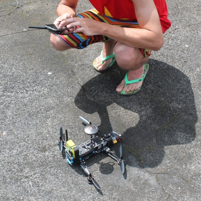
First, about the application with which the route is set on the map. This is a tower . Together with him, you will have to install 3DR Services to connect the modem to Android. The application is quite stable and functional, you can use offline maps or simply upload Google Maps in advance. About all the features and skills of using this application is easy to learn from the following video.
It is worth noting that at the initial stages it is better not to remove the radio from the drone and have the remote control on hand to intercept the rotor in manual control, since errors may occur during launches via Tower, while the program interface is not fully understood.
The first thing you should pay attention to is the flight altitude set manually. It is often difficult from the outside to determine the height at which the copter must pass in order not to touch anything. It is worth practicing in determining the height "by eye". But still it does not save when flying over long distances, when the view is blocked by closer objects.
Second, you should always remember about the conditions of operation of the GPS and magnetometer described above. In this regard, it is necessary to carefully select the launching pad. To check the compass, you can see if the turns of the copter on the ground are 90 or 180 degrees, with the readings of the course angle in the Tower. The error should not exceed 15 degrees.
The third is security. It is better to take off and landings away from people and animals, and also not to fly in the forbidden zones.
Experience of using the device and conclusion.
The embodiment of the idea of a small copter, flying independently along the route, can be accepted. A minimum of necessary things, including five batteries and a charger, take up very little space in the baggage. In 10 minutes of flight, the copter is able to fly 1.5-2 km and return. It is necessary to recognize the sufficient reliability of the device - no failures have ever happened. In this case, the tests were held in St. Petersburg, when the temperature was kept near zero degrees, and the main flights were in the heat of 30-35 degrees. By the way, you can see the video of the first flights 1 , 2 , 3 and 4 . In total, about 2 hours of video were filmed and 40 sorties were made in various locations.
Of course, there were mistakes. Two times in the journey, the copter crashed into obstacles. This is completely connected with the incorrect installation of the flight altitude, since in the first case there was a mountainous terrain, and in the second there were literally ten centimeters lacking. Three times during landing, the so-called “ toiletbowls ” were observed, because large metal buildings were nearby. At the same time, the landings were not very successful, but without breakdowns. I did not greatly appreciate the ability to use the Follow Me mode, it is worth modifying. In this mode, the flight is uncertain.
I will also highlight the main drawback of such a copter - this is the absence of a gyro-stabilized suspension and, as a result, a jerky video. But unfortunately, without losing the duration of the flight, the suspension for Xiaomi Yi does not fit into the given size.
In general, the project can be considered successful. Thanks to the drone received unforgettable travel footage. Although it is necessary to recognize that there is something to work on and, perhaps, create a new version.
Source: https://habr.com/ru/post/372343/
All Articles