Practical use of ROS on the Raspberry Pi - part 4
This is the last fourth article planned in the series . In this article I will talk about using the PS3 Dualshock joystick to control the robot through ROS using the example of controlling a simple servo used in the tutorial for rosserial_arduino. Who cares, I ask under the cat.
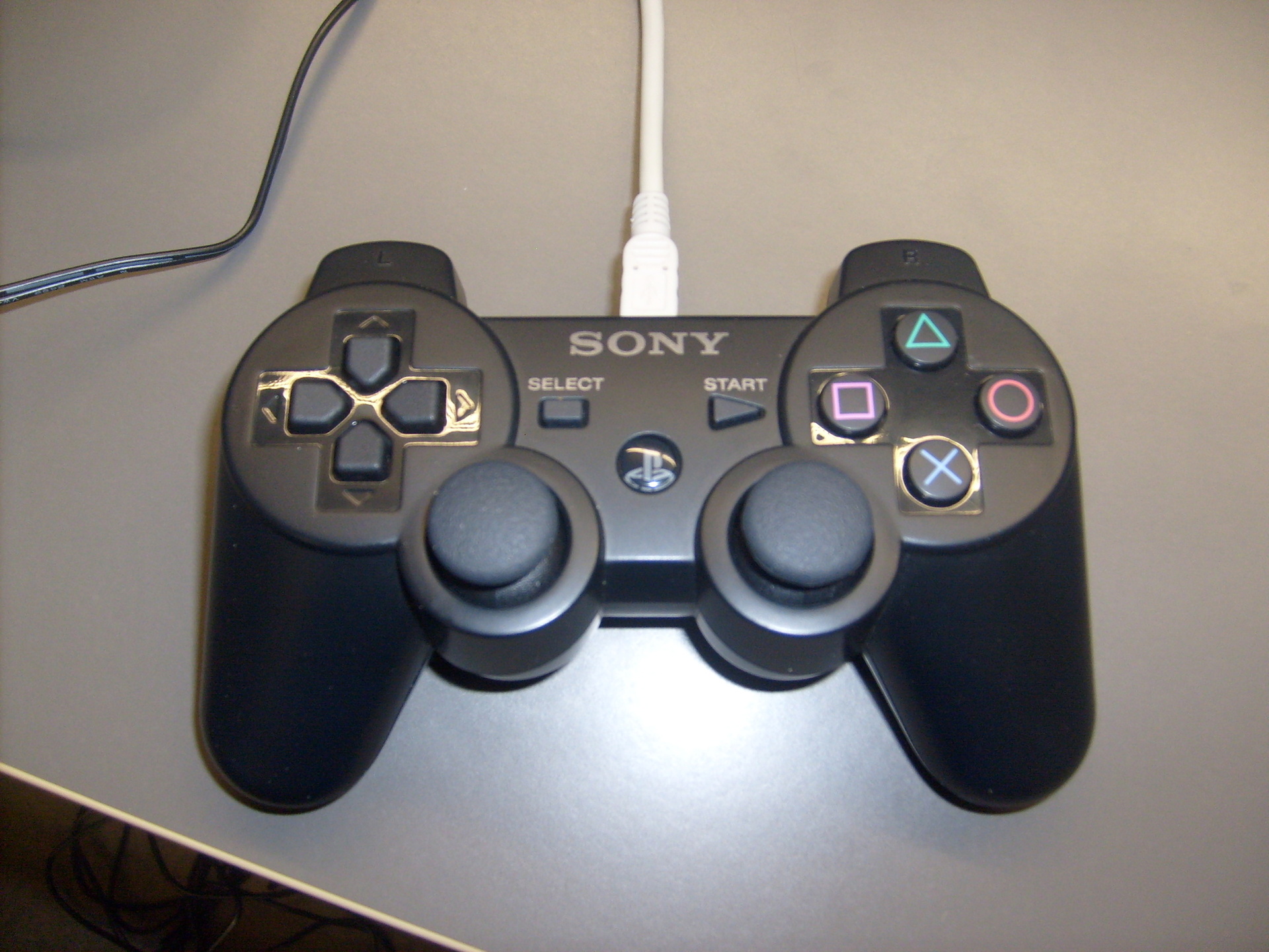
We need the PS3 Dualshock joystick itself
')
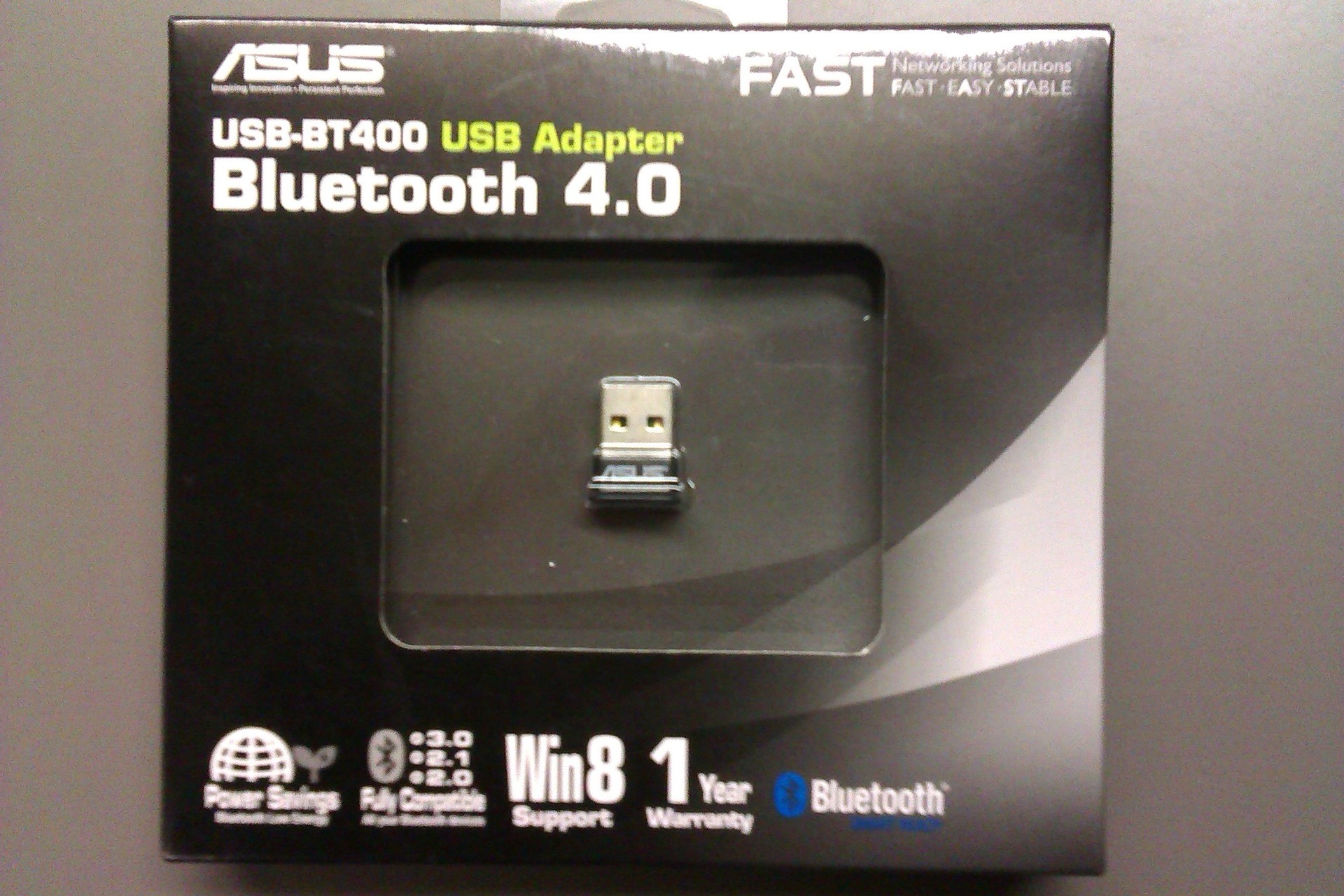
and a Bluetooth adapter, such as
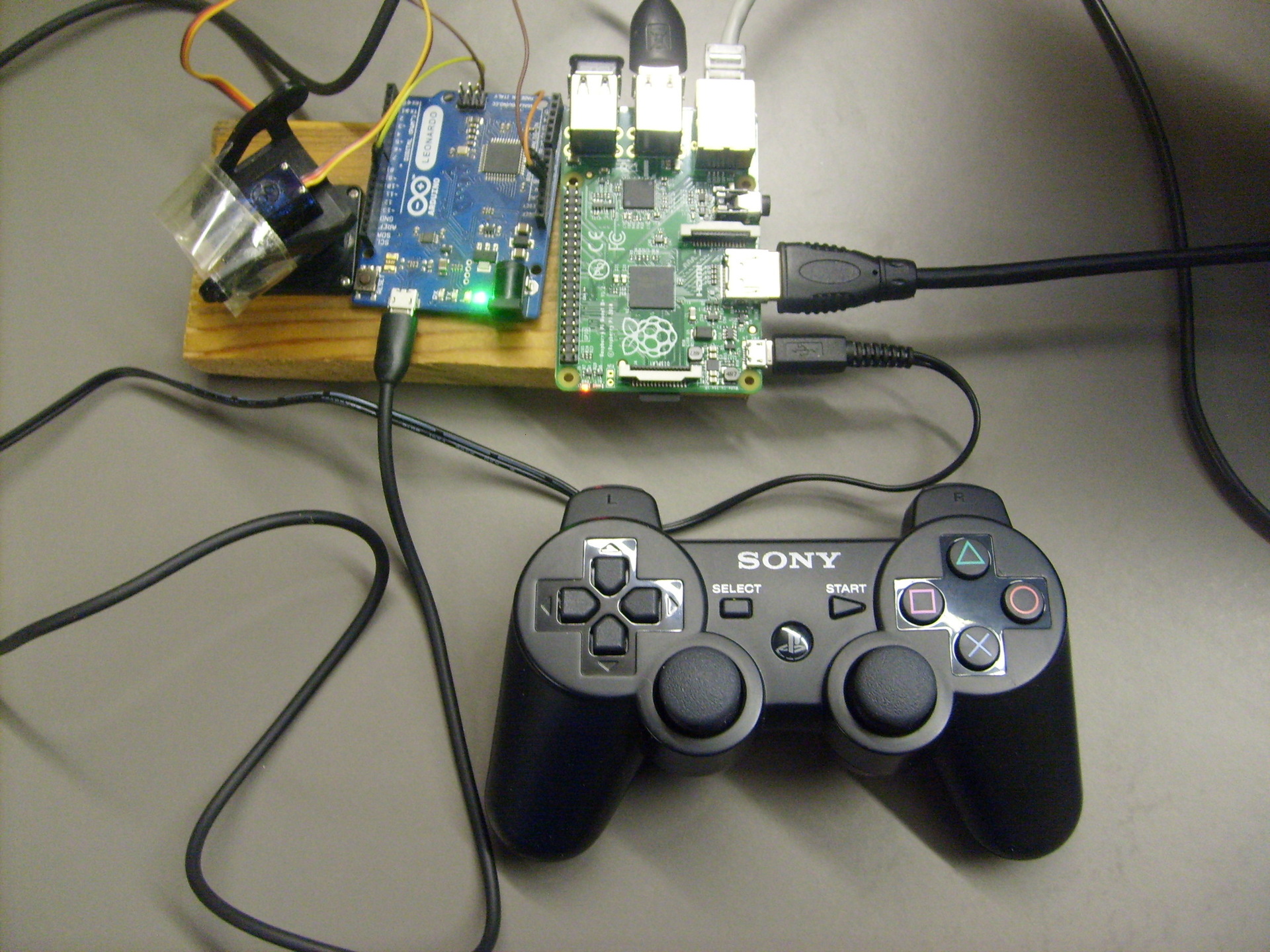
I also use a camera mount (for example, this ), controlled by a servo:
We need the RetroPie-Setup script to install hardware support for the Dualshock joystick on the Raspberry Pi.
Download it from here and install it:
First choose Update ReproPie-Setup.
Then run the retropie_setup.sh script again. Choose Setup / Configuration> 310 Install / Pair PS3 controller. Follow the instructions, install.
After the installation is complete, you will need to connect the joystick to the USB port and click OK. After that, you need to disconnect the joystick from the USB port and press the round PS button. A Bluetooth connection will be established. Now the joystick is paired and ready to use.
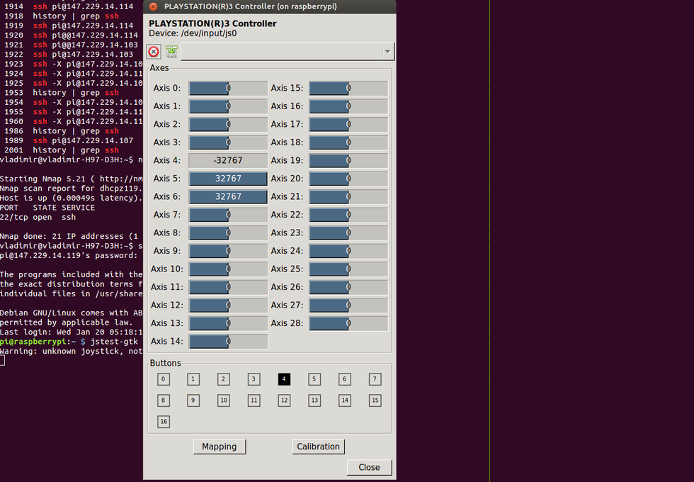
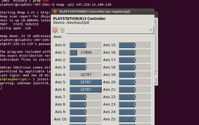
You can test the joystick using the jstest-gtk graphical utility:
Run the utility:
The program interface is very simple.

Try pressing the buttons and you should instantly see how the progress bars next to the corresponding axis names for the bumper buttons begin to change or the button lights appear when you press the button.
After pressing the buttons you will see the following picture.
After pressing the buttons "bumper" you will see the following picture
To use the joystick in ROS you need to install the appropriate packages:
The joystick_drivers stack includes all the necessary nodes and drivers. The primary goal of this stack is to convert joystick events to ROS messages.
In particular, we will need a joy node. A detailed description of it can be found on the page along with tutorials here and here .
First, let's start the joy node:
Connect the joystick, press the round power button PS and execute:
The output will be something like this:
Messages posted by the joy node are of type sensor_msgs / Joy and include linear and angular velocity. Speed values are included in the axes field: the first value determines the angular velocity, the second one - linear.
You can see the structure of Joy messages with the command:
The command will show the following structure:
We will create a sketch to control the servo. Create a sketch. To control the server, we will need the Arduino Servo library. Connect the servo to the Arduino can be viewed in the tutorial .
We write the sketch. To begin with, add a header file for the sensor_msgs / Joy messages at the top of the file:
Add header files for the Servo library and for ROS:
The following is the standard code for the rosserial_arduino sketch:
In the setup method, we bind the servo to pin 9 and perform the standard initialization of the rosserial_arduino node.
In the sketch should pay attention to the lines:
where we specify the indices for the angular and linear velocity values in the axes array in the sensor_msgs / Joy message. We simply create a subscriber for the joy topic and in the servo_cb method we process the received message. Here we extract the angular and linear velocity values. In this sketch, we use only the angular velocity, since we determine the rotation of the serva.
The direction of rotation is determined based on the ratio of the joystick buttons and the direction of the axes. An example for the two main bumper buttons can be seen on the image from the page .

Here it is indicated that axis 16 sets the rotation (left click - positive value, right - negative). In accordance with this rule, in the sketch, the turn is determined to the left - to the right (angular velocity - the angular field).
Axis 17 sets the movement forward - backward: forward - positive, backward - negative. The values of this axis correspond to the linear velocity (linear field):
Using the camera mount, you can mount and control the Raspberry Pi Camera Board camera by rotating the servo:

Thus, you can write the controller logic for a mobile robot by defining control actions to specific buttons of the joystick (controlling the “bumper” button using the tilt or using the up-down-left-left-right) buttons.
As you can see, you can find many uses of the joystick to control the robot. All this is possible thanks to the fact that ROS provides a convenient interface for connecting the PS3 Dualshock joystick to a robot on the Raspberry Pi platform and makes it very simple to implement the control logic of various servo robot actuators.
I wish everyone good luck in robotic projects using ROS and Raspberry Pi!
PS3 Joystick Support Installation (Dualshock)
We need the PS3 Dualshock joystick itself
')
and a Bluetooth adapter, such as
I also use a camera mount (for example, this ), controlled by a servo:
We need the RetroPie-Setup script to install hardware support for the Dualshock joystick on the Raspberry Pi.
Download it from here and install it:
git clone https://github.com/RetroPie/RetroPie-Setup.git cd RetroPie-Setup/ sudo ./retropie_setup.sh First choose Update ReproPie-Setup.
Then run the retropie_setup.sh script again. Choose Setup / Configuration> 310 Install / Pair PS3 controller. Follow the instructions, install.
After the installation is complete, you will need to connect the joystick to the USB port and click OK. After that, you need to disconnect the joystick from the USB port and press the round PS button. A Bluetooth connection will be established. Now the joystick is paired and ready to use.
You can test the joystick using the jstest-gtk graphical utility:
sudo apt-get install jstest-gtk. Run the utility:
jstest-gtk The program interface is very simple.
Try pressing the buttons and you should instantly see how the progress bars next to the corresponding axis names for the bumper buttons begin to change or the button lights appear when you press the button.
After pressing the buttons you will see the following picture.
After pressing the buttons "bumper" you will see the following picture
To use the joystick in ROS you need to install the appropriate packages:
rosinstall_generator ros_comm joystick_drivers image_transport --rosdistro indigo --deps --wet-only --exclude roslisp --tar > indigo-custom_ros.rosinstall wstool update -t src rosdep install --from-paths src --ignore-src --rosdistro indigo -y -r --os=debian:jessie sudo ./src/catkin/bin/catkin_make_isolated --install -DCMAKE_BUILD_TYPE=Release --install-space /opt/ros/indigo The joystick_drivers stack includes all the necessary nodes and drivers. The primary goal of this stack is to convert joystick events to ROS messages.
In particular, we will need a joy node. A detailed description of it can be found on the page along with tutorials here and here .
Using the ROS joystick
First, let's start the joy node:
rosrun joy joy_node Connect the joystick, press the round power button PS and execute:
rostopic echo joy The output will be something like this:
--- axes: (0.0, 0.0, 0.0, 0.0) buttons: (0, 0, 0, 0, 0) --- axes: (0.0, 0.0, 0.0, 0.12372203916311264) buttons: (0, 0, 0, 0, 0) --- axes: (0.0, 0.0, -0.18555253744125366, 0.12372203916311264) buttons: (0, 0, 0, 0, 0) --- Messages posted by the joy node are of type sensor_msgs / Joy and include linear and angular velocity. Speed values are included in the axes field: the first value determines the angular velocity, the second one - linear.
You can see the structure of Joy messages with the command:
rosmsg show sensor_msgs/Joy The command will show the following structure:
std_msgs/Header header uint32 seq time stamp string frame_id float32[] axes int32[] buttons We will create a sketch to control the servo. Create a sketch. To control the server, we will need the Arduino Servo library. Connect the servo to the Arduino can be viewed in the tutorial .
We write the sketch. To begin with, add a header file for the sensor_msgs / Joy messages at the top of the file:
#include <sensor_msgs/Joy.h> Add header files for the Servo library and for ROS:
#include <Servo.h> #include <ros.h> The following is the standard code for the rosserial_arduino sketch:
ros::NodeHandle nh; Servo servo; // Indices of components in joy message int linear_ind = 1; int angular_ind = 0; void servo_cb(const sensor_msgs::Joy& joy) { float angular = joy.axes[angular_ind]; float linear = joy.axes[linear_ind]; int cur_pos = servo.read(); if(angular > 0) { nh.loginfo("Turn left"); cur_pos = cur_pos - 20; servo.write(cur_pos); } else if(angular < 0) { nh.loginfo("Turn right"); cur_pos = cur_pos + 20; servo.write(cur_pos); } } ros::Subscriber<sensor_msgs::Joy> sub("joy", &servo_cb); void setup() { pinMode(13, OUTPUT); nh.initNode(); nh.subscribe(sub); servo.attach(9); // attach it to pin 9 } void loop() { nh.spinOnce(); delay(1); } In the setup method, we bind the servo to pin 9 and perform the standard initialization of the rosserial_arduino node.
In the sketch should pay attention to the lines:
// Indices of components in joy message int linear_ind = 1; int angular_ind = 0; where we specify the indices for the angular and linear velocity values in the axes array in the sensor_msgs / Joy message. We simply create a subscriber for the joy topic and in the servo_cb method we process the received message. Here we extract the angular and linear velocity values. In this sketch, we use only the angular velocity, since we determine the rotation of the serva.
The direction of rotation is determined based on the ratio of the joystick buttons and the direction of the axes. An example for the two main bumper buttons can be seen on the image from the page .
Here it is indicated that axis 16 sets the rotation (left click - positive value, right - negative). In accordance with this rule, in the sketch, the turn is determined to the left - to the right (angular velocity - the angular field).
Axis 17 sets the movement forward - backward: forward - positive, backward - negative. The values of this axis correspond to the linear velocity (linear field):
float linear = joy.axes[linear_ind]; Using the camera mount, you can mount and control the Raspberry Pi Camera Board camera by rotating the servo:
Thus, you can write the controller logic for a mobile robot by defining control actions to specific buttons of the joystick (controlling the “bumper” button using the tilt or using the up-down-left-left-right) buttons.
As you can see, you can find many uses of the joystick to control the robot. All this is possible thanks to the fact that ROS provides a convenient interface for connecting the PS3 Dualshock joystick to a robot on the Raspberry Pi platform and makes it very simple to implement the control logic of various servo robot actuators.
I wish everyone good luck in robotic projects using ROS and Raspberry Pi!
Source: https://habr.com/ru/post/372331/
All Articles