Fast high-voltage movements, or almost the whole truth about stepper motor control
Good day to you, dear geeks and sympathizers!
In this post I want to share my management experience. More precisely - control steps. And if to be completely accurate, we will discuss the management of a wonderful device - a stepper motor.
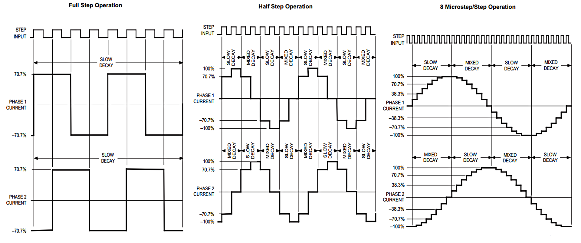
What is this same stepping motor? In principle, in terms of functionality, this motor can be represented as an ordinary electric motor, each turn of the shaft of which is divided into many identical, exactly fixed steps. By moving a certain number of steps, we can position the shaft of the stepping motor with high accuracy and good repeatability. Each step can be divided into many steps (the so-called microstepping), which increases the smoothness of the motor, contributes to the suppression of resonances, and also increases the angular resolution. Differences between full-step mode (left), 1/2 microstepping (center) and 1/16 microstepping (right) are visible to the naked eye:
Unfortunately, all the above-mentioned advantages are achieved at the cost of the considerable complexity of the stepper motor control system (for simplicity, we will call this system a driver).
Now consider the scheme of a typical stepper motor:
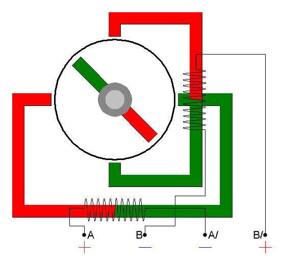
From this picture it can be seen that a stepping motor in electrical terms consists of two or more electromagnets that must be switched in a certain sequence in order to set the rotor in motion.
Lyrical digression: Currently, there are two basic types of stepping motors: unipolar and bipolar. Since unipolar motors have lower torque and lower speed characteristics, they will not be considered in this publication.
So back to the management of a bipolar motor. Paradoxically, it is often easier to discuss general principles with concrete examples. As an example, we take the stepper motor ST4118L1804-A manufacturer Nanotec. Why is this motor and manufacturer? The reason is simple: in terms of basic characteristics, this is a typical representative of NEMA 17 type motor, which is widely used in amateur radio practice, and also has quite detailed technical documentation (which is absent from Chinese noname motors).
')
The main characteristics of this motor:
Operating voltage 3.15 V
Operating current 1.8 A
The winding resistance of 1.75 Ohms
Winding inductance 3.3 mH
Hold moment 0.5 Nm
Angle pitch 1.8 ° (200 steps per rotor rotation)
In this case, the most important thing is the correct interpretation of the data. Applying Ohm's law, we find out that the manufacturer indicated the operating current and voltage for direct current flowing through the motor windings, without taking into account the inductance.
Check: I = U / R, or 1.8 A = 3.15 V / 1.75 Ohms. It all fits together.
What is the power dissipation when powering the windings with direct current?
It's simple: P = I x U, or 1.8 A x 3.15 V = 5.67 watts. In the half-step mode, a situation is possible when the current flows through both motor windings, respectively, the power dissipated must be doubled: 5.67 W x 2 = 11.34 W. This is quite a lot, and can lead to overheating of the motor. This value is the minimum power supply for this motor. An ordinary 3D printer has five such motors; accordingly, a power supply with a minimum power of 11.34 W x 5 = 56.7 W is needed to power the drivers. To this figure it is necessary to add the electrical power converted by the motor into kinetic or potential energy when the printer is operating. The exact calculation of this power is quite complicated, in practice it is easiest to add 75% to the calculated thermal power and to complete the calculations. Why exactly 75%? The fact is that a conventional stepper motor is capable of performing useful work of about 2/3 of the maximum thermal power. In this case, to create any node or device, first a suitable motor is selected (for example, by torque), and then the power of the power supply unit is calculated.
The total capacity of the power supply for the five stepper motors: 56.7 W x 1.75 = 99.225 W.
Of course, in practice, no amateur device uses motors under maximum load, and the actual power consumption will most likely be much lower than the calculated one. I, as a person lazy and stingy, extremely do not like to do the same thing twice, so I always take the power supply with some margin (that is, according to the above calculations).
Now it's time to start determining the minimum required voltage of the power supply. Unfortunately, this parameter is given unduly little attention in thematic publications. Why is this parameter so important? The fact is that when the rotor rotates a stepper motor, an alternating current flows through the coils, limited not only by the active, but also the inductive resistance of the windings.
Consider the graph provided by the manufacturer of the torque of our motor versus speed:
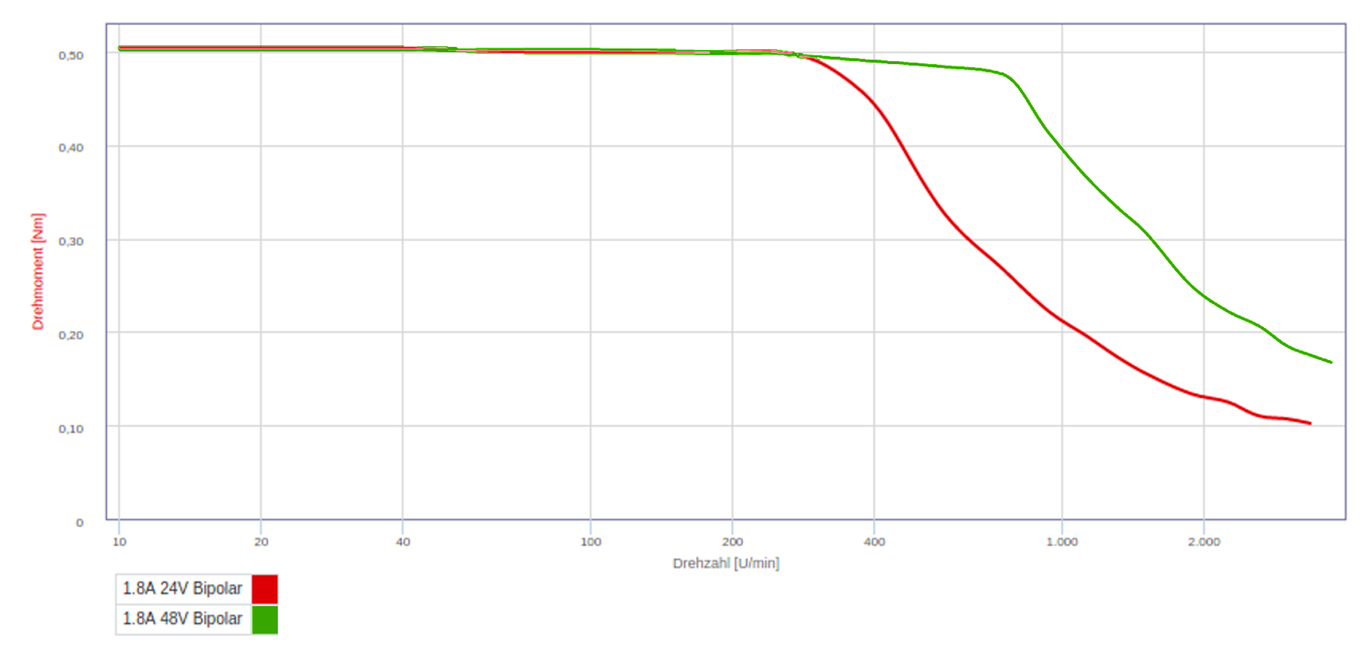
The graph has two lines showing the dependence of torque on the rotational speed for the supply voltage of 24 V (red line) and 48 V (green line). It is easy to see that the decline in torque starts from about 300 rpm for 24 V and from about 600-700 rpm for a voltage of 48 V. It should be mentioned that the manufacturer uses expensive industrial drivers that are inaccessible to fans. Why is the driver supply voltage so important, if it even in the case of power supply from 12 V is obviously higher than the nominal value of the supply voltage of the stepping motor (3.15 V)? The fact is that a stepper motor is controlled by current, not voltage, and it is the current sources that are all modern drivers. In the ideal case, the driver provides the specified current in the motor windings, regardless of the rotor speed, load, temperature change and other parameters. This is organized at the expense of the PWM controller, which is often controlled by quite complex algorithms. From the technical documentation of our motor, it is clear that for a complete revolution the rotor needs to complete 200 steps, at 300 rpm it will be 60,000 steps per minute, or 1000 steps per second. This, simply put, corresponds to an alternating current frequency of 1 kHz. At this frequency, the inductive impedance of the winding will be (R (L) = 2π × F × L): 2π x 1 kHz x 3.3 mH = 20.73 Ohms. What kind of voltage is necessary to provide a current of 1.8 A with this resistance? Ohm's law is not asleep (U = IR): 1.8 A x 20.73 Ohm = 37.31 V. It is not surprising that a decrease in torque is observed above the speed of 300 rpm: the driver simply does not have enough supply voltage. Why, with such a glaring lack of power (37 - 24 = 13 V) does the fall not occur at a lower frequency of rotation? The fact is that modern drivers use a bridge circuit of the output stages, which allows you to "double" the voltage applied to the motor windings. That is, in theory, the driver is able to apply “virtual” 48 V to the windings at a supply voltage of 24 V, which creates a theoretical margin of 48 - 37 = 11 V. In practice, this margin will be leveled by driver losses, associated circuits and active resistance of the windings motor (the resistance of the windings is constantly present, and even increases slightly when the motor is heated). As the rotor speed increases above 300 rpm, the frequency of the pulses increases proportionally and, accordingly, the inductive resistance of the winding increases. When powered from 24 V, the driver no longer has enough supply voltage to maintain the current in the windings, and the torque is steadily decreasing. The same thing happens when the driver is powered from 48 V, but much later, at a speed of 600-700 rpm.
So, with the power and voltage of the power supply unit everything is clear, now it is necessary to move on to the practical implementation of a universal driver capable of both filigree work using tiny NEMA 11 and shaking the foundations of the world paired with powerful NEMA 23. What are the main qualities have a driver of my dreams?
1. High supply voltage. Since the maximum voltage of the power supply is extremely rare in the technical documentation for motors, it will be better to limit to 48 V.
2. The most important parameter: high output current. NEMA 23 have working currents up to 3.5 A, the driver must provide this current with a margin of 30%. By simple calculations, we get the maximum operating current of about 4.5 A.
3. Simple and quick adjustment of the output current.
4. The presence of microstepping at least 1/8 step
5. Availability of protection against short circuit, overheating, etc.
6. Small size, the possibility of mounting an arbitrary radiator.
7. Execution in the form of an integrated circuit. XXI century in the yard!
8. Simple wiring diagram with a minimum number of discrete components.
9. Low price.
After a
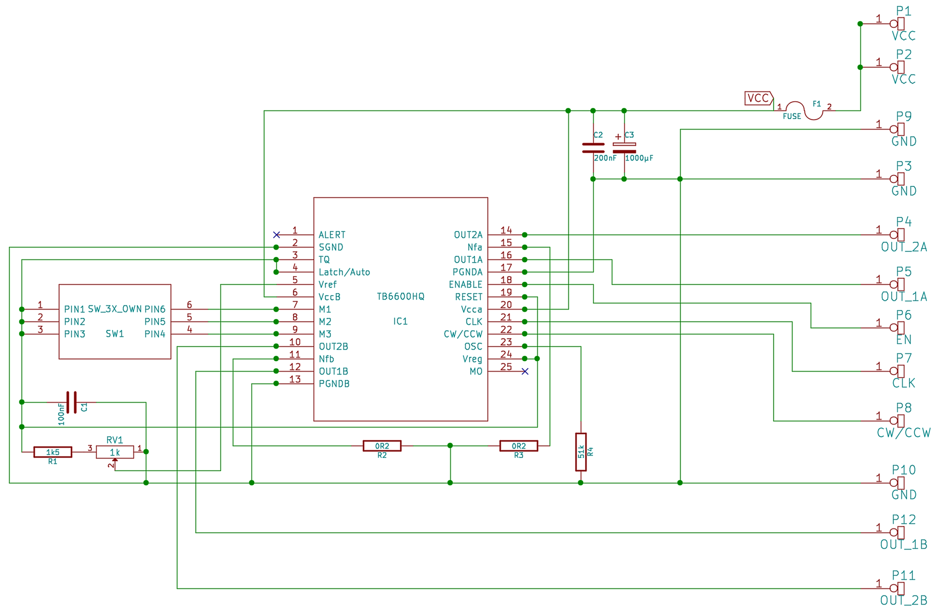
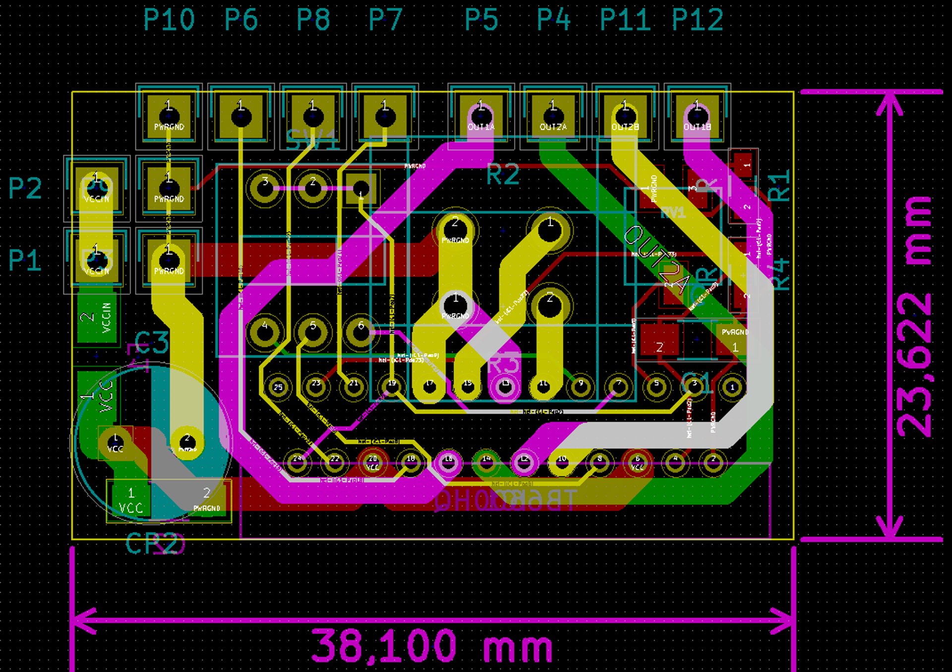
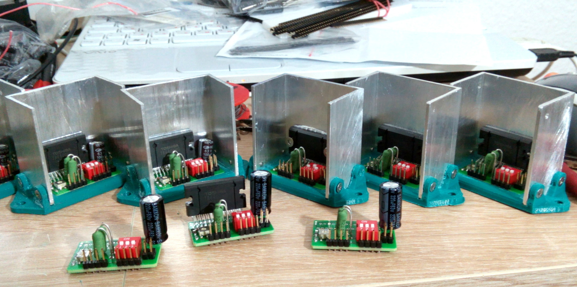
In order to minimize the size, a four-layer printed circuit board was designed. This fact, unfortunately, excludes its production at home. Therefore, at the Berlin company LeitOn, 36 such boards were ordered, each of which cost about five euros in total. A part of these boards were subsequently bought out by my fellow enthusiasts, and as a result, the production of the boards turned out to be not too expensive. TBB6600HG chips were ordered on Aliexpress for 4 euros per piece, the rest of the components were ordered on eBay, in terms of one driver, the price of discrete components was 2 euros. Five-centimeter lengths of U-shaped aluminum profile were taken as radiators; plastic frames were printed on a 3D printer. Total price of one driver was about 12 euros. This is a fair price for a driver with the following characteristics:
Power supply from 8 to 42 volts
The maximum long-term operating current is 4.5 Amps, set by potentiometer
Microstepping up to 1/16 of a step
Protection: short circuit, overheating, low supply voltage
Compact size and low weight
Work with input signal levels from 3.3 to 5.5 volts
Simple installation of microstepping with the help of microswitches - to hell jumpers!
Ready printed circuit boards:

Collected and unfinished drivers.
Video of the driver in my old 3D printer. Here, the three-amp NEMA 17 cheerfully chases a heated work platform of a printer measuring 45 x 25 cm across a sixteen-millimeter spindle 60 cm long:
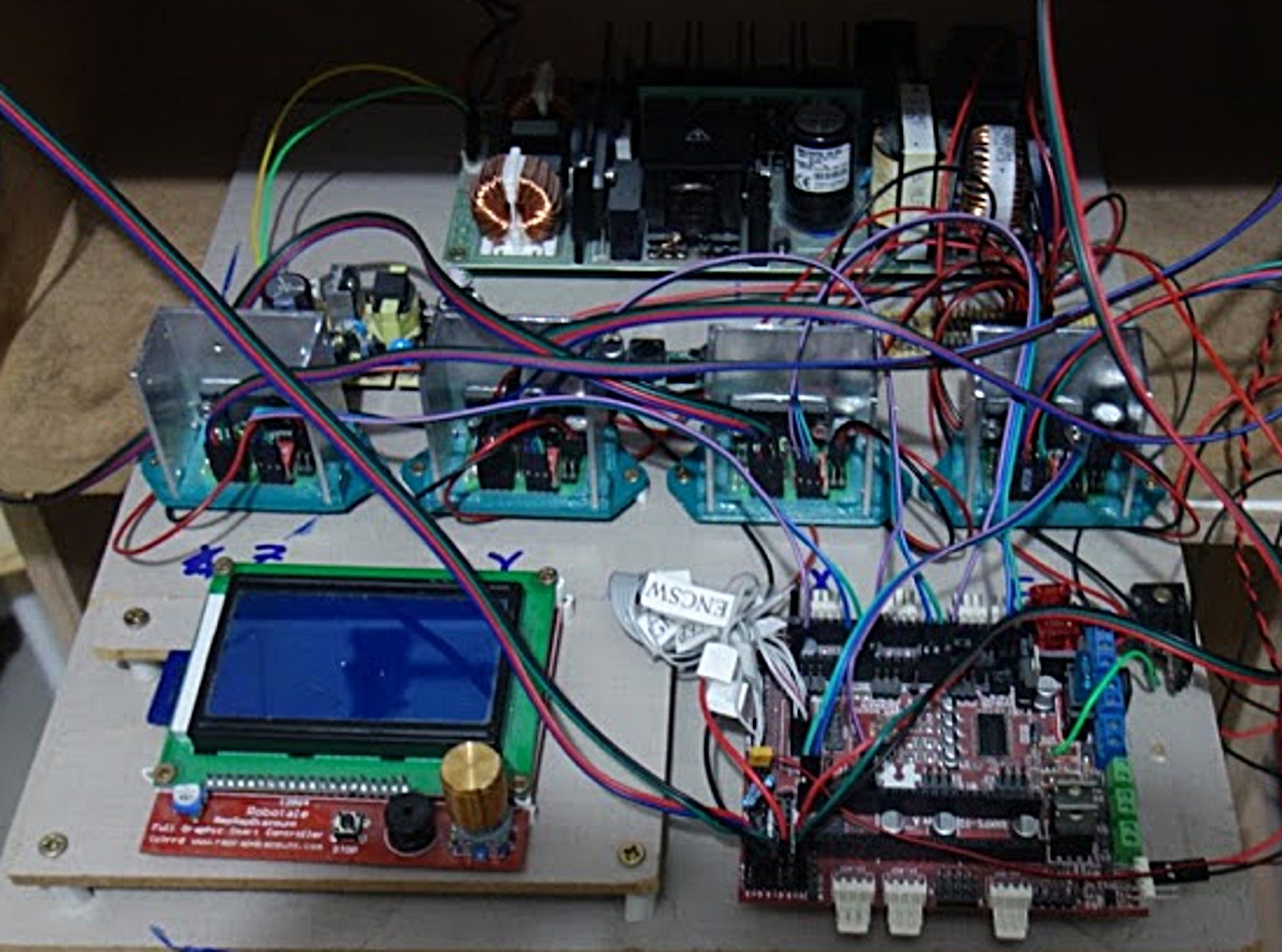
The final photo: homemade drivers in my workplace in my new 3D printer.
Published under the WTFPL license.
Well, and traditional: Have fun!
Source: https://habr.com/ru/post/372249/
All Articles