How to manage "advertising" LED-matrices
In recent years, widespread in outdoor advertising and a variety of information boards led matrix. Rather bright, dynamic - they perfectly attract attention and do not go blind on a sunny day. Each of you sees them on the streets of your city every day.
Of course, the low price (due to Chinese manufacturers) and the simplicity of screen assembly contributed to their spread.
But what if you try to apply these matrices in your devices on microcontrollers? What is the exchange interface and output logic for these matrices?
Let's try to figure it out.
The Chinese offer both the matrixes themselves of different sizes and with different resolutions, as well as controllers for displaying images with various simple effects on them, as well as all the necessary accessories, connecting cables, frames.
Matrices are found as monochromatic (white, yellow, red, green, blue), and 3-color (RGB). The designation of a matrix model usually looks like Pxx or PHxx, where xx is a number indicating the distance between pixels in millimeters. In my case, this is P10. In addition, matrices of some sizes are not only rectangular, but also square.
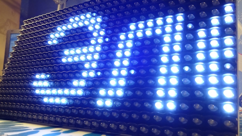
So, we have a white matrix of 32x16 pixels with dimensions of 320x160 mm and, accordingly, an interpixel distance of 10 mm. Let's take a closer look at it.
Front view:

Do you also think that the LEDs are oval? You did not think ...

A small visor is made above the LEDs, which does not allow the sunlight to illuminate the LEDs.
')
We turn over the matrix and see the board:

On the board a handful of logic chips. Let's see what these chips are:
1. 1 x SM74HC245D - non-inverting buffer
2. 1 x SM74HC04 - 6-channel inverter
3. 1 x SM74HC138D - 8-Bit Decoder
4. 4 x APM4953 - build from 2 P-channel MOSFET
5. 16 x 74HC595D - latch shift register
Two 16-pin connectors are interfaced, one of them is input (the screen controller is connected to it), and the second is output (the next matrix in the chain is connected to it). The arrow on the board is directed from the input connector to the output.
Power is supplied to the terminals in the center of the board. The supply voltage is 5V, the maximum current (when all LED arrays are on) is 2A (for a white matrix).
The site managed to find the pinout connector (s) of the matrix:

Also on the site we managed to find a schematic diagram, which quite accurately corresponds to the scheme of my matrix:
On the connector:
- Pins 6, 14, 16 (C, G, D) - not used (perhaps they are used in 3-color matrices).
- Pins 2 and 4 (A and B) - specify which of the 4 groups of screen LEDs is working at the moment. Matrices use dynamic indication, alternately switching 4 groups of LEDs depending on the logic levels on legs A and B. On the board, these signals come to the D18 decoder, which opens 1 of 4 groups of P-channel fieldmasters, thereby applying + 5V to the anodes of the LEDs selected groups.
- Pin 1 (nOE) - allows the matrix to work (log. 0 suppresses all matrices in the chain). The operation logic of this pin is implemented on the elements NOT in D19 and the decoder D18.
- Pins 8 and 12 (CLK and R) are the lines of the clock and data of the synchronous serial interface. They are connected to the SCK and MOSI SPI interface of the microcontroller.
- Pin 10 (SCLK) - on the leading edge, the data transmitted to the shift registers is latched onto their outputs. The shift registers are connected to the cathodes of the matrix LEDs. For this reason, the transmitted data must be inverted (the LED will be lit at log. 0).
All signals except the signal R are connected at the input and output interface connectors of the matrix via the buffer. The signal R passes from the input connector through the buffer to the first shift register of the matrix and, passing through the entire chain of registers, goes to the output interface connector. Thus, all the shift registers of all matrices are included in one long chain.
Based on this, the logic of updating the screen (more precisely, a quarter of the screen) is as follows:
1. We issue SPI data for shift registers. For one 32x16 matrix, this is 16 bytes (16 8-bit registers).
2. Install the log. 0 on the leg nOE.
3. Install the log. Levels on the legs A and B in accordance with the updated group of LEDs (one of the four). This supplies + 5V to the anodes of the LEDs of the selected group.
4. We issue a short positive impulse to the SCLK stem. This supplies ground to the cathodes of the LEDs according to the bytes loaded into the registers.
5. Install the log. 1 on the leg nOE. In this case, a quarter of the screen (one group of LEDs) lights up and lights up until the next update of the next group of LEDs.
Repeat points 1-5 with a constant period.
My implementation of this algorithm and a small demo of the matrix:
Project source for AVR ATmega328 (IAR)
Project source for STM32f103c8t6 (IAR)
All the above information, as well as a demonstration of the matrix in the video below. In it, from 13:04 to 15:00 I'm talking about the dependence of the brightness of the screen on the number of matrices. This is due to an error in the algorithm. The error is corrected and now the data is loaded before the screen is turned off.
Also I will be glad to see you on my youtube-channel , where I connect many more things to microcontrollers.
Thank you all for your attention!
Of course, the low price (due to Chinese manufacturers) and the simplicity of screen assembly contributed to their spread.
But what if you try to apply these matrices in your devices on microcontrollers? What is the exchange interface and output logic for these matrices?
Let's try to figure it out.
The Chinese offer both the matrixes themselves of different sizes and with different resolutions, as well as controllers for displaying images with various simple effects on them, as well as all the necessary accessories, connecting cables, frames.
Matrices are found as monochromatic (white, yellow, red, green, blue), and 3-color (RGB). The designation of a matrix model usually looks like Pxx or PHxx, where xx is a number indicating the distance between pixels in millimeters. In my case, this is P10. In addition, matrices of some sizes are not only rectangular, but also square.
Possible options for matrix sizes
So, we have a white matrix of 32x16 pixels with dimensions of 320x160 mm and, accordingly, an interpixel distance of 10 mm. Let's take a closer look at it.
Front view:
Do you also think that the LEDs are oval? You did not think ...
A small visor is made above the LEDs, which does not allow the sunlight to illuminate the LEDs.
')
Front view with a plastic mask removed
We turn over the matrix and see the board:
On the board a handful of logic chips. Let's see what these chips are:
1. 1 x SM74HC245D - non-inverting buffer
2. 1 x SM74HC04 - 6-channel inverter
3. 1 x SM74HC138D - 8-Bit Decoder
4. 4 x APM4953 - build from 2 P-channel MOSFET
5. 16 x 74HC595D - latch shift register
Two 16-pin connectors are interfaced, one of them is input (the screen controller is connected to it), and the second is output (the next matrix in the chain is connected to it). The arrow on the board is directed from the input connector to the output.
Power is supplied to the terminals in the center of the board. The supply voltage is 5V, the maximum current (when all LED arrays are on) is 2A (for a white matrix).
The site managed to find the pinout connector (s) of the matrix:
Also on the site we managed to find a schematic diagram, which quite accurately corresponds to the scheme of my matrix:
On the connector:
- Pins 6, 14, 16 (C, G, D) - not used (perhaps they are used in 3-color matrices).
- Pins 2 and 4 (A and B) - specify which of the 4 groups of screen LEDs is working at the moment. Matrices use dynamic indication, alternately switching 4 groups of LEDs depending on the logic levels on legs A and B. On the board, these signals come to the D18 decoder, which opens 1 of 4 groups of P-channel fieldmasters, thereby applying + 5V to the anodes of the LEDs selected groups.
- Pin 1 (nOE) - allows the matrix to work (log. 0 suppresses all matrices in the chain). The operation logic of this pin is implemented on the elements NOT in D19 and the decoder D18.
- Pins 8 and 12 (CLK and R) are the lines of the clock and data of the synchronous serial interface. They are connected to the SCK and MOSI SPI interface of the microcontroller.
- Pin 10 (SCLK) - on the leading edge, the data transmitted to the shift registers is latched onto their outputs. The shift registers are connected to the cathodes of the matrix LEDs. For this reason, the transmitted data must be inverted (the LED will be lit at log. 0).
All signals except the signal R are connected at the input and output interface connectors of the matrix via the buffer. The signal R passes from the input connector through the buffer to the first shift register of the matrix and, passing through the entire chain of registers, goes to the output interface connector. Thus, all the shift registers of all matrices are included in one long chain.
Based on this, the logic of updating the screen (more precisely, a quarter of the screen) is as follows:
1. We issue SPI data for shift registers. For one 32x16 matrix, this is 16 bytes (16 8-bit registers).
2. Install the log. 0 on the leg nOE.
3. Install the log. Levels on the legs A and B in accordance with the updated group of LEDs (one of the four). This supplies + 5V to the anodes of the LEDs of the selected group.
4. We issue a short positive impulse to the SCLK stem. This supplies ground to the cathodes of the LEDs according to the bytes loaded into the registers.
5. Install the log. 1 on the leg nOE. In this case, a quarter of the screen (one group of LEDs) lights up and lights up until the next update of the next group of LEDs.
Repeat points 1-5 with a constant period.
My implementation of this algorithm and a small demo of the matrix:
Project source for AVR ATmega328 (IAR)
Project source for STM32f103c8t6 (IAR)
All the above information, as well as a demonstration of the matrix in the video below. In it, from 13:04 to 15:00 I'm talking about the dependence of the brightness of the screen on the number of matrices. This is due to an error in the algorithm. The error is corrected and now the data is loaded before the screen is turned off.
Also I will be glad to see you on my youtube-channel , where I connect many more things to microcontrollers.
Thank you all for your attention!
Source: https://habr.com/ru/post/372215/
All Articles