Inertial tracker based on Arduino and GY-85
Hi geektimes . Head tracker, sometimes it is also called inertial tracker - a device that tracks the movement of the head in space, that is, in three axes - X, Y, Z.
Today I will tell you how you can move the mouse cursor with the help of head movements, although everything is not limited to just turnips, you can use any other moving part of the body, such as an arm.
')
This video, for the most part, duplicates the text of the article.
The target audience of this device, as I see it at the moment, will be approximately as follows:
- Gamers, this solution is great for all kinds of flight simulators, be it War Thunder or space simulators, such as Elite Dangerous (just below there will be an example of use), and simulators in general, where the mouse is mostly used for review, although they say that Arma 2 is also well played. At the beginning of the video, I showed work in GTA5 with the third person view turned on, and I will tell you that these are completely different sensations from the game, although it is difficult to aim, and there are some other nuances specifically in this game, like for example - you still have to a little "taxi" with the mouse;
- People with disabilities, I think if you seriously develop this topic, you can facilitate the use of computers for people who have difficulty using them;
- VR device developers (virtual reality);
- RC modellers and copter drivers;
- Same tech geeks like me .
In order to repeat this device, we need the following hardware:
- Arduino, the best solution in this case is Arduino Nano V3 (inexpensive, relatively small size), it is imperative that the board be with an ATmega328 microcontroller on board. It would also not be bad if there was a USB to UART converter on the CH340 chip in Arduinka:

So that there are no problems with the lack of memory in the microcontroller or drivers, such as with arduinkami based on FT232RL chips .
Argument in favor of ATmega328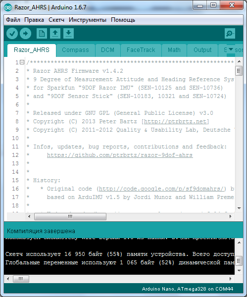
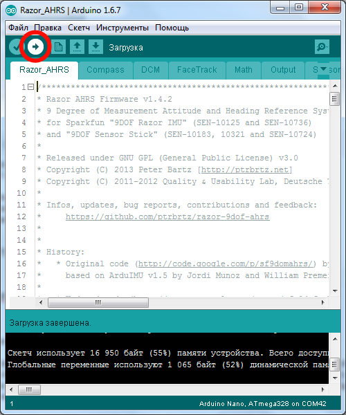
The code, as can be seen from the screenshot above, takes about 16 kilobytes of microcontroller memory, which is definitely not enough if the Arduink is based on ATmega168, although of course you can cut out not quite the necessary functionality from the firmware and thus try to fit. But why?
The code, as can be seen from the screenshot above, takes about 16 kilobytes of microcontroller memory, which is definitely not enough if the Arduink is based on ATmega168, although of course you can cut out not quite the necessary functionality from the firmware and thus try to fit. But why?
Drivers for the chip CH340G look in the first links for the query "ch340g driver" in Google , or in the archive for this article.
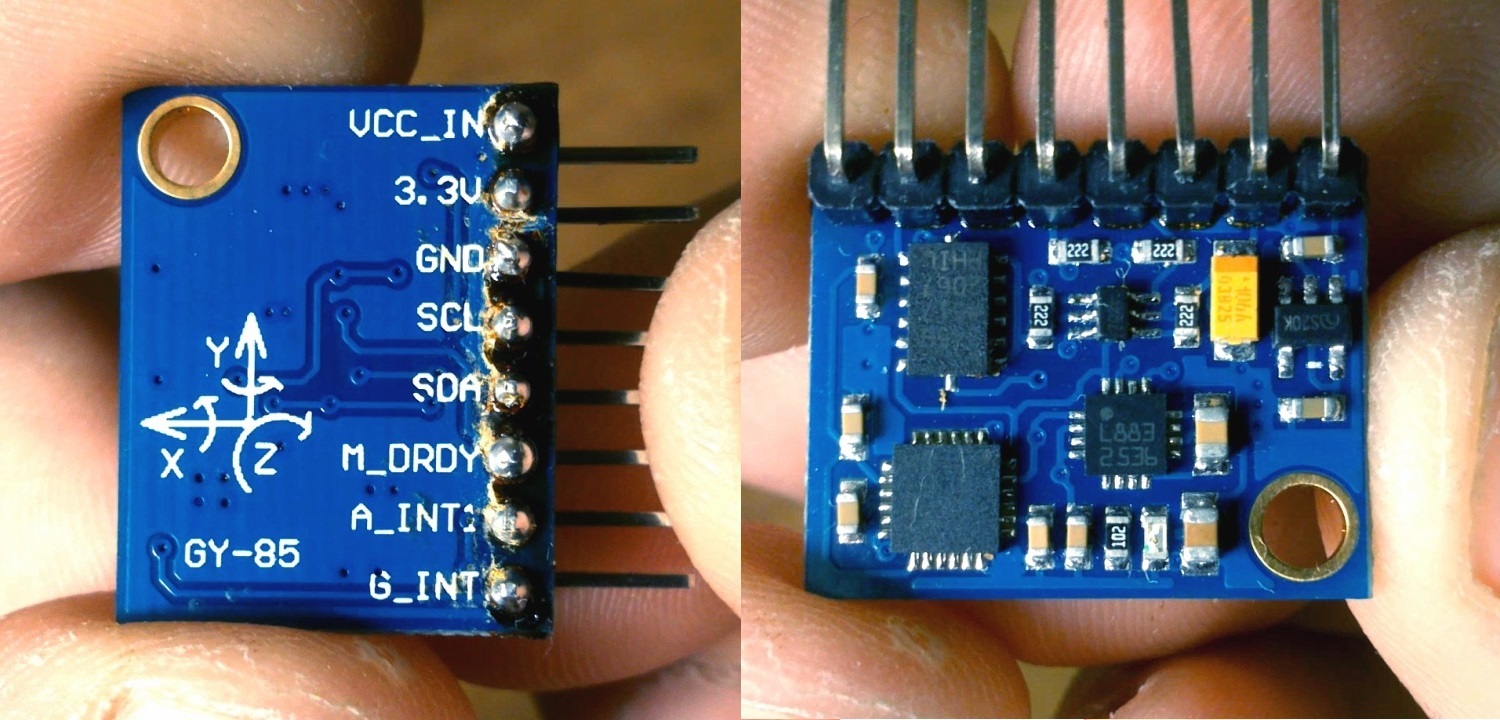
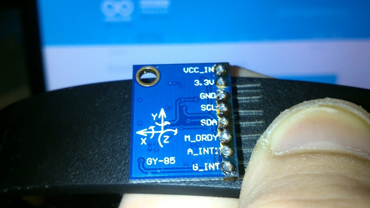
- The GY-85 sensor is a three-axis MPU3200 gyroscope, an ADXL345 accelerometer and a HMC5883L magnetometer on a single board. This is more than enough to navigate in space in three axes.
He showed himself the best, does not require preliminary calibrations, hooked up, flashed arduinka and works. Although AHRS (Kursovertikal) firmware and allows calibration, but this is a separate topic, which, I believe, is more than fully disclosed on the forum on the game WarThunder ;
- A different trifle - wires, a soldering iron (you can't do without it, because, like the Arduino Nano and GY-85 come from China in the soldered state), a USB extension cable, a Mini-USB cable for the Arduino Nano V3.
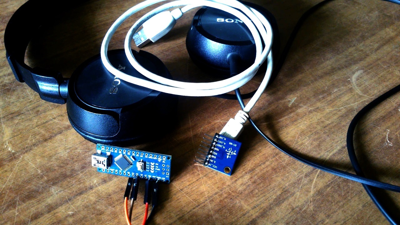
Head Tracker Assembly:
We connect Arduino and GY-85, in the case of Arduino Nano it will be like this:
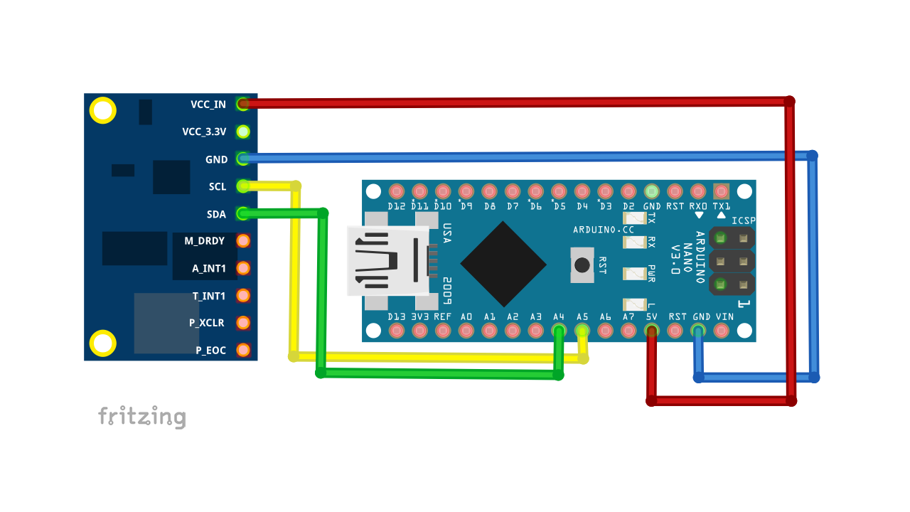
- VCC_IN -> 5V;
- SCL -> A5;
- SDA -> A4;
- GND -> GND.
We supply power to the Arduino - the LED should be lit on the sensor.
In the case of Head Tracker, the sensor is ideally attached to the bezel of the headphones, as I did on the “Krivoruk” line:

I am sure that you will do it more carefully than me.
Arduino screwed the board with a normal wire from a twisted pair, so as not to shorten anything on the board, the insulation from the wire was not removed, everything is fine, if you do not constantly pull at it.
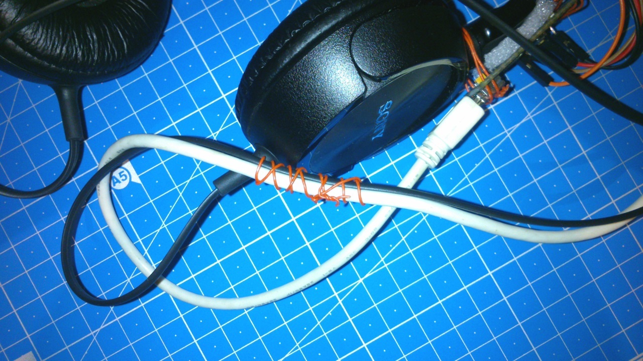
As for not pulling the board, I just twisted the USB cable and headphone cable with the same wiring from the twisted pair.
I also wanted to do the same with the sensor, but through trial and error I found out that this is not an option, I will write below why. Just tied everything together, it turned out like this:

I put a piece of polyethylene foam under the sensor, as well as under the Arduinka, so that they would not scratch my headphones, and so it would be better kept.
True, there are some points, it is important to position the sensor so that the arrow Y points to the monitor.
It is also necessary to keep the sensor away from metal objects, the recommended distance is 5-10 cm. Otherwise there may be a distortion of the readings, glitches in the operation of the sensor. This is true for those who have a metal bezel headphones. Although not only metal can distort the readings, but also arduinka itself or even wires, which was shown on the video , so try to remove it all from the sensor at least at a distance of 5-10 cm.
The simplest solution with a metal headband is a sponge for washing dishes:

Since I have a plastic bezel (it was checked by a magnet), I scored on all this.
Firmware:
If you still have not installed the latest version of the Arduino IDE - download and install. At the time of writing, this is 1.6.8.
In our inertial tracker, we will use the custom firmware of the project AHRS Firmware for the SparkFun 9DOF Razor IMU and SparkFun 9DOF Sensor Stick ( archive with everything you need at the bottom of the article ). In the Arduino IDE, open the Razor_AHRS.ino file, which is archived along the DIY headtracker \ RazorAHRS_FaceTrack \ Razor_AHRS path:

And we load the firmware in Arduino:
OpenTrack setup:
OpenTrack is a free, open source program designed to track user head movements and convert them into coordinates. Able to work with different input devices, including IR frame and Oculus Rift, or with smartphones.
In the video, the dude plays the Elite Dangerous cult game using his Android smartphone as a mouse:
This allowed us to use both hands for the gameplay. Agree, it looks very cool. True, I don’t like a few nuances in this implementation, namely, the smartphone is relatively bulky and heavy, the GY-85 clearly takes up space and weighs less, besides, the radiation from the WiFi transmitter of the smartphone doesn’t hammer into it.
You can read more here:
https://github.com/opentrack/opentrack/wiki/Smartphone-Headtracking
But let's go back to our Arduino and GY-85
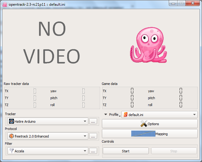
Now we need to configure the program - in the “Tracker” field, select “Hatire Arduino” and press the "..." button and we will see something like this:
Hatire Arduino Settings Window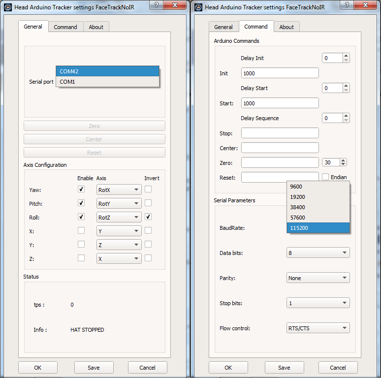
Here it is necessary to change the “Serial port” to the COM port of our arduinka, in my case it is COM42. Next, go to the tab "Command", register there, in the fields "Init" and "Start" 1000, then set "BaudRate" 115200, and finally click "Save" and "OK".
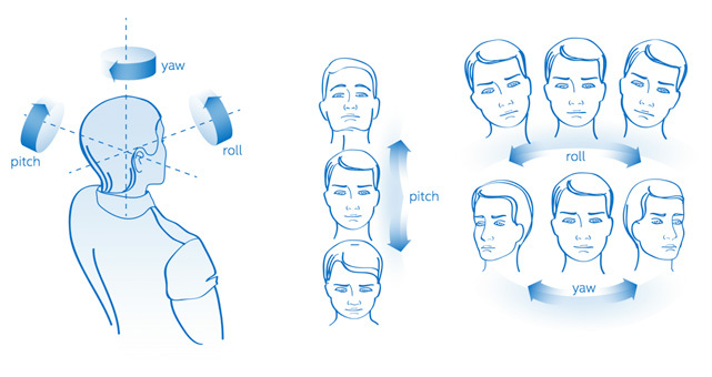
Further in the main window of the program we press the “Start” button, we begin to rotate the sensor in different axes and monitor the octopus. Most likely, the movements of the sensor and the octopus will be different, at least in my case it happened, without stopping the tracking, click the "..." button in the "Tracker" field. Here we need to configure the “Axis Configuration” so that the sensor movements coincide with the movements of the octopus in the program — we set the Yaw, Pich and Roll values to RotX / RotY / RotZ in the correct sequence, this will help us picture:
As I did, you can see on the settings screen “Hatire Arduino” which is higher. The axis “Roll” had to be inverted, because the octopus was spinning in the opposite direction.
The program also allows you to adjust the sensitivity for each of the axes - the "Mapping" button in the main program window:
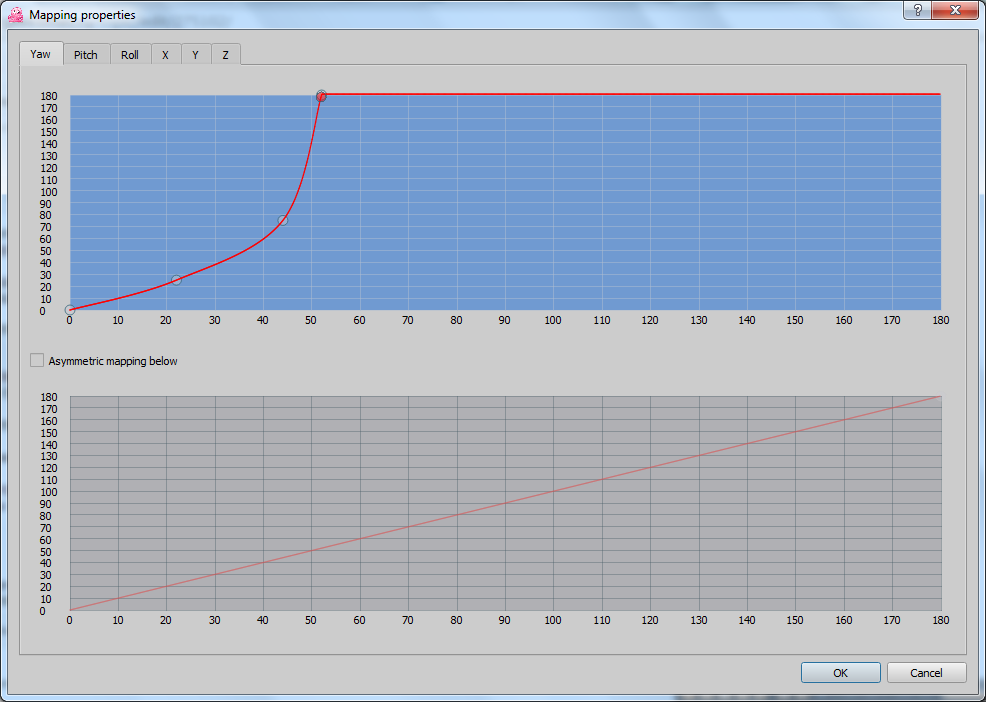
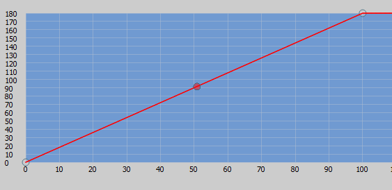
With the right mouse button you can set and move points, the left mouse button deletes points, you can put several points to eliminate non-linearity in the sensor reading, if any. All my axes are configured like this:
The “Filter” tab in the main window of the program allows you to change the filter type, or disable it altogether, in this case, the readings will be very unstable and abrupt. My filter type is “Accela” with these settings:

If you wish, you can play around with the settings.
Go to the mouse emulation setting, for this, in the Protocol tab, select mouse emulation and press the "..." button, there you need to set Yaw and Pich for the X, Y axes:

Press the start button and voila - prevention of cervical osteochondrosis. And finally, I’ll add that before pressing the start button, you need to set the head exactly relative to the monitor, because the sensor is calibrating at this moment.
Results:
Pluses before the option with the use of a web camera and IR LEDs:
- The speed, this firmware gives out about 60 readings per second, which is approximately equal to a web camera at 60 fps, but it seems to me that a webcam at 60 frames per second is clearly more expensive than the GY-85 and Arduino boards;
- No dependency on lighting;
- Since almost all calculations are produced by arduino, the processor resources of the computer are unloaded, that is, there are fewer glitches in games;
- It can be used not only for games, but also to facilitate the use of PC for people with disabilities.
Minuses:
- Wired connection, which in principle can be solved using a Bluetooth module, for example as HC-05 / HC-06. The firmware supports this feature.
- The sensor is relatively expensive, I bought mine for $ 8, which I consider overpriced;
- Worry aesthetic look of headphones, but I'm sure you will do better than me.
Surely many will have a question, what is the point of turning your head around the monitor if it is standing still? As I said in the video, this is just the beginning of the VR theme on my YouTube channel.
Useful links on the topic:
Archive to the article , with all necessary;
Branch of the forum on the game WarThunder , where there is a lot of interesting things on the topic of the article;
Always fresh version of Arduino IDE ;
Project AHRS Firmware for the SparkFun 9DOF Razor IMU and SparkFun 9DOF Sensor Stick ;
Custom firmware project above , sharpened by working with the program OpenTrack;
A similar project using a smartphone as a position sensor ;
Always fresh and working version of the OpenTrack program is here ;
Similar publication from comrade Sergey Novoselov SergeNovo
Self-made inertial tracker for 3-D points and not only ;
All my publications are on geektimes .
PS There is another option, when OpenTrack does not emulate mouse movements, but directly interacts with the game, but I can write about this some other time, or you can figure it out yourself; I asked the vector to develop this theme;
PPS If anyone needs it, here's the GY-85:
GY-85-SCH.jpg
Source: https://habr.com/ru/post/372171/
All Articles