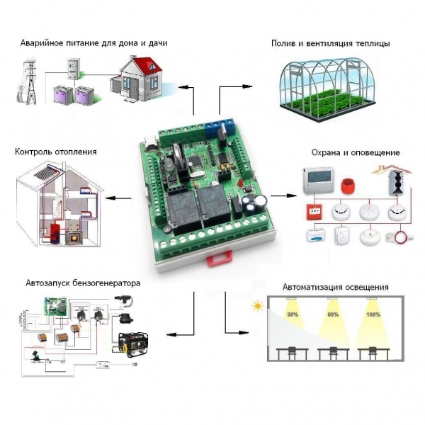
We manage the autonomous power of a country house
Most of us have summer houses, and someone generally lives year-round in a private house or cottage. The problem of power outages on the periphery is familiar firsthand. The easiest way out of the situation is to light a candle and humbly wait for the best, but nowadays this is not always acceptable. More advanced gardeners got generators, only they must be started and stopped manually. In the dark and in the cold season it is uncomfortable to do. And there are situations when the owners are not at home at all, however, stopping the supply of energy can lead to the shutdown of the heating control systems at home and other critical situations. In such cases, it is simply necessary to automate the processes of transition from the main power supply to the backup and vice versa. In the first part, we will look at an example of the operation of the MP8036multi module in controller mode (mixed mode, example 1), which controls the autonomous power supply of a country house. And also we give a wiring diagram and an example of a working debugged program.
This task is not as simple as it seems. First, you need to monitor the presence of voltage in the network, and to distinguish short-term voltage fluctuations from the actual cases of cessation of energy supply. Secondly, it is not enough just to apply voltage to start the generator - it is also necessary after some time to check whether it has started and how it works stably, and only after that switch the power supply network to the backup line. Thirdly, throughout the whole time of the generator operation it is desirable to monitor its state: oil pressure, fuel level, etc. It is also necessary to control the availability and stability of the mains voltage, and after the electricity supply is resumed, smoothly stop the generator, letting it idle, and only after that switch consumers to the main line.
Accordingly, the control controller must support operation with temperature sensors, have at least two ADC inputs, eight independent outputs for controlling starters and relays, an output for signaling and indication - and at the same time have the capabilities of a flexible configuration. All these requirements are met by the new Master Kit - the multifunctional MP8036multi controller.
')
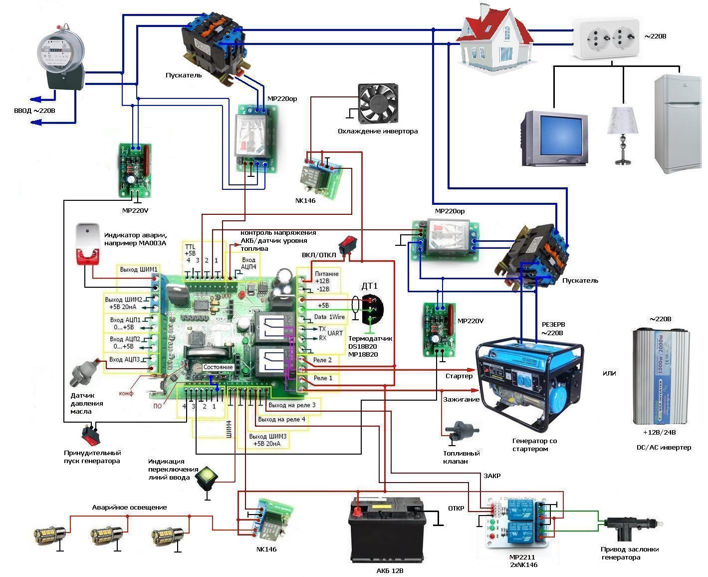
In general approximation, the automatic control system will have the following main controls and alarms:
- Sensor MP220V №1 (input control);
- Sensor MP220V №2 (generator control);
- MP220op №1 (ON / OFF input, delay);
- MP220op №2 (ON / OFF generator delay);
- NK146 №1 (ON / OFF emergency lighting);
- MP2211 No. 1 (opening damper actuator);
- MP2211 No. 2 (closing damper actuator);
- ignition / fuel valve;
- starter start (RELAY 1 output);
- control of oil pressure;
- control the temperature of the inverter;
- NK146 №2 inverter cooling;
- battery charge control;
- alarm indicator / temperature sensor health;
- input line switching indicator.
Algorithm of the module
When the power is turned on, the module checks for mains voltage of 220V using the MP220V sensor (input 4). If there is no mains voltage, the module using the MP220op optole (Output 1) disconnects the power line from the meter and starts the generator or inverter start algorithm (Relay 1) and (Relay 2).
After the launch, the module waits 15 seconds - during this time the generator should go into operating mode. After that, using the MP220op relay (Output 2), the power line of the house is connected to the high-voltage socket of the generator. The generator start control is performed using the MP220V mains voltage sensor connected to Input 3 of the module.
When operating from a generator, the module constantly monitors the presence of a 220V mains voltage at the input (Input 4). As soon as 220V appears on the home electric meter, the controller will disconnect the power supply line from the generator to the house (Output 2). To cool the generator will work for 30 seconds in idle mode, after which it will be stopped.
After 35 seconds of a stable supply voltage of 220V, at the meter input, the module connects the power line at home (Output 1). At this time, despite the absence of voltage in the sockets, emergency lighting is automatically turned on (Output PWM3).
When using a DC / AC inverter, there is a two-threshold temperature control. When the temperature exceeds 60 ° C, the inverter cooling fan turns on (Output 3). If the temperature continues to rise, then at 90C there will be a power line disconnection at home (Exit 2). Then the module will wait for the inverter to cool to 60C, after which it will resume powering again (Output 2).
In all positions, when there is no voltage in the power line at home, emergency lighting is turned on using the PWM3 output. Since emergency lighting is battery powered, it is better to use LED lights or ribbons to save energy.
With the help of input 3, the module can control the oil pressure in the crankcase of the generator, and at emergency low pressure the generator will be stopped.
With the help of the ACP4 input, when working with a generator, the module can control the level of fuel in the tank, and when working with a DC / AC inverter, it charges the batteries, protecting them from deep discharge.
At the output of PWM4, the indication of the switching of the power line at home is implemented.
At the outputs PWM1 implemented alarm:
- low oil pressure in crankcase (Input ATsP3);
- low battery charge (ADC4 input);
- DC / AC inverter overheating (Input Data).
For gasoline generators, a generator damper control is provided using the outputs of relay 3 and relay 4. When using a diesel generator, a glow plug can be connected to the output of relay 4 to heat the incoming air into cold weather. When using a DC / AC inverter, the outputs of relay 3, relay 4 and relay 2 are not used.
The program of the module is written in such a way that allows you to control any type of generator: both gasoline and diesel. If necessary, you can use DC / AC inverter required power. When working with an inverter program code does not need to change.
The wiring diagram and the program text are shown below:
All used PWM channels are switched to discrete output mode. But if necessary, they can always be used as intended.
When practicing the program, do not forget to add the DT1 temperature sensors according to the configuration instructions. Please note that when adding two or more sensors, you must connect them in turn. The time intervals and temperature range are adjusted locally.
Each time the program is loaded into the module’s memory, the configurator program must be restarted.
At first glance it may seem that everything is very difficult. But in fact, you just need to understand the algorithm, as on any other device. You take one of the inputs as a basis and just start to describe the conditions. In this case, Input 4 was taken as the basis.
If necessary, you can always correct the algorithm for a particular task.
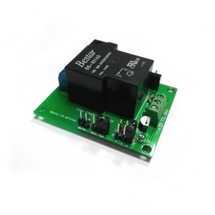
With a total power consumption of electrical appliances up to 7 kW, the MP146 power module can be used instead of the MP220op + starter:
To be continued …
The authors of the decision: E.A. Sapunov, V.A. Rublev (UA4LOU)
Attention!
Only from 02/18/2016 to 10-00 02/24/2016 the MP8036 multi is subject to a festive price, you can buy it for 5,000.00 rubles!
Discount on the product is combined with a discount for online payment!
This task is not as simple as it seems. First, you need to monitor the presence of voltage in the network, and to distinguish short-term voltage fluctuations from the actual cases of cessation of energy supply. Secondly, it is not enough just to apply voltage to start the generator - it is also necessary after some time to check whether it has started and how it works stably, and only after that switch the power supply network to the backup line. Thirdly, throughout the whole time of the generator operation it is desirable to monitor its state: oil pressure, fuel level, etc. It is also necessary to control the availability and stability of the mains voltage, and after the electricity supply is resumed, smoothly stop the generator, letting it idle, and only after that switch consumers to the main line.
Accordingly, the control controller must support operation with temperature sensors, have at least two ADC inputs, eight independent outputs for controlling starters and relays, an output for signaling and indication - and at the same time have the capabilities of a flexible configuration. All these requirements are met by the new Master Kit - the multifunctional MP8036multi controller.
')
In general approximation, the automatic control system will have the following main controls and alarms:
- Sensor MP220V №1 (input control);
- Sensor MP220V №2 (generator control);
- MP220op №1 (ON / OFF input, delay);
- MP220op №2 (ON / OFF generator delay);
- NK146 №1 (ON / OFF emergency lighting);
- MP2211 No. 1 (opening damper actuator);
- MP2211 No. 2 (closing damper actuator);
- ignition / fuel valve;
- starter start (RELAY 1 output);
- control of oil pressure;
- control the temperature of the inverter;
- NK146 №2 inverter cooling;
- battery charge control;
- alarm indicator / temperature sensor health;
- input line switching indicator.
Algorithm of the module
When the power is turned on, the module checks for mains voltage of 220V using the MP220V sensor (input 4). If there is no mains voltage, the module using the MP220op optole (Output 1) disconnects the power line from the meter and starts the generator or inverter start algorithm (Relay 1) and (Relay 2).
After the launch, the module waits 15 seconds - during this time the generator should go into operating mode. After that, using the MP220op relay (Output 2), the power line of the house is connected to the high-voltage socket of the generator. The generator start control is performed using the MP220V mains voltage sensor connected to Input 3 of the module.
When operating from a generator, the module constantly monitors the presence of a 220V mains voltage at the input (Input 4). As soon as 220V appears on the home electric meter, the controller will disconnect the power supply line from the generator to the house (Output 2). To cool the generator will work for 30 seconds in idle mode, after which it will be stopped.
After 35 seconds of a stable supply voltage of 220V, at the meter input, the module connects the power line at home (Output 1). At this time, despite the absence of voltage in the sockets, emergency lighting is automatically turned on (Output PWM3).
When using a DC / AC inverter, there is a two-threshold temperature control. When the temperature exceeds 60 ° C, the inverter cooling fan turns on (Output 3). If the temperature continues to rise, then at 90C there will be a power line disconnection at home (Exit 2). Then the module will wait for the inverter to cool to 60C, after which it will resume powering again (Output 2).
In all positions, when there is no voltage in the power line at home, emergency lighting is turned on using the PWM3 output. Since emergency lighting is battery powered, it is better to use LED lights or ribbons to save energy.
With the help of input 3, the module can control the oil pressure in the crankcase of the generator, and at emergency low pressure the generator will be stopped.
With the help of the ACP4 input, when working with a generator, the module can control the level of fuel in the tank, and when working with a DC / AC inverter, it charges the batteries, protecting them from deep discharge.
At the output of PWM4, the indication of the switching of the power line at home is implemented.
At the outputs PWM1 implemented alarm:
- low oil pressure in crankcase (Input ATsP3);
- low battery charge (ADC4 input);
- DC / AC inverter overheating (Input Data).
For gasoline generators, a generator damper control is provided using the outputs of relay 3 and relay 4. When using a diesel generator, a glow plug can be connected to the output of relay 4 to heat the incoming air into cold weather. When using a DC / AC inverter, the outputs of relay 3, relay 4 and relay 2 are not used.
The program of the module is written in such a way that allows you to control any type of generator: both gasoline and diesel. If necessary, you can use DC / AC inverter required power. When working with an inverter program code does not need to change.
The wiring diagram and the program text are shown below:
PROGRAM TEXT
// INPUT4 - MP220V sensor input control
// INPUT3 - MP220V sensor generator control
// OUT1 - MP220op ON / OFF input, delay
// OUTPUT2 - MP220op generator ON / OFF delay
// PWM3 - NK146 ON / OFF emergency lighting
// INPUT1 - button with latching Start / Stop
// RELAY4 - MP2211 Flap Drive Opening
// RELAY 3 - MP2211 Damper actuator closing
// RELAY1 - ignition / fuel valve
// RELAY2 - starter 4 sec
// ACP3 - <5V oil pressure control
// DT1 - inverter temperature control
// OUTPUT 3 - NK146 inverter cooling
// ACP4 - <10.5V battery charge control
// PWM1 - alarm indicator / temperature sensor operability
// PWM4 - input line switching indicator
CONFIGURATION RESET
OUTPUT1. MODE_PO_MULSE = 1
OUTPUT1. MODE1. STATUS = 0
OUTPUT1. MODE1. DELAY = 5 (s)
OUTPUT1. MODE1. CONDITION1: INPUT4 = 1
OUTPUT1. MODE1. LOGIC_OUTIONS = U1
OUTPUT1. MODE2. STATUS = 1
OUTPUT1. MODE2. DELAY = 35 (s)
OUTPUT1. MODE2. CONDITION1: INPUT4 = 0
OUTPUT1. MODE2. LOGIC_OUTIONS = U1
OUTPUT2.REW_NUMBERING MODE = 1
OUTPUT2. MODE1. STATUS = 0
OUTPUT2. MODE1. DELAY = 15 (s)
OUTPUT2. MODE1. CONDITION1: INPUT4 = 0
OUTPUT2. MODE1. CONDITION2: ACP3 <= 5
OUTPUT2. MODE1. CONDITION3: ACP4 <= 10.5
OUTPUT2. MODE1. CONDITION4: DT1> = 90
OUTPUT2. MODE1. CONDITION5: OUTPUT1 = 1
OUTPUT2. MODE1. CONDITION6: INPUT1 = 1
OUTPUT2. MODE1. CONDITION7: INPUT3 = 1
OUTPUT2. MODE1. CONDITION8: INPUT4 = 1
OUTPUT2. MODE1. CONDITION9: PWM1 = 1
OUTPUT2. MODE.LOGICA_USLOVY = U1 OR Y2 OR Y3 OR Y4 OR Y5 OR Y6 OR Y9 OR (Y7 And Y8)
OUTPUT2. MODE2. STATUS = 1
OUTPUT2. MODE2. DELAY = 15 (s)
OUTPUT2. MODE2. CONDITION1: INPUT3 = 0
OUTPUT2. MODE2. CONDITION2: DT1 <= 60
OUTPUT2. MODE2. CONDITION3: ACP3> = 5
OUTPUT2. MODE2. CONDITION4: ACP4> = 10.5
OUTPUT2. MODE2. CONDITION5: INPUT4 = 1
OUTPUT2. MODE2. LOGIC OF THE CONDITIONS = U1 AND U2 AND U3 AND U4 AND U5
OUTPUT3. MODE_PO_MULSE = 1
OUTPUT3. MODE1. STATUS = 0
OUTPUT3. MODE1. CONDITION1: DT1 <= 60
OUTPUT3. MODE1. CONDIT2: INPUT3 = 1
OUTPUT3. MODE1. LOGIC OF THE CONDITIONS = U1 OR U2
OUTPUT3. MODE2. STATUS = 1
OUTPUT3. MODE2. CONDITION1: DT1> = 90
OUTPUT3. MODE2. LOGIC OF THE CONDITIONS = U1
RELAY 1. MODE_PO_MULSE = 1
RELAY 1. MODE. STATUS = DISABLED
RELAY 1. MODE. DELAY = 30 (s)
RELAY1. MODE1. CONDITION1: INPUT4 = 0
RELAY1. MODE1. CONDITION2: ACP3 <= 5
RELAY1. MODE1. CONDITION3: ACP4 <= 10.5
RELAY 1. MODE1. CONDITION4: DT1> = 90
RELAY1. MODE1. CONDITION 5: INPUT 3 = 1
RELAY 1. MODE1. CONDITION6: OUTPUT4 = 1
RELAY1. MODE1. CONDITION7: PWM1 = 1
RELAY1. MODE1. LOGIC OF THE CONDITIONS = U1 OR U2 OR Y3 OR U4 OR U7 OR (U5 And Y6)
RELAY 1. MODE. STATUS = ENABLE
RELAY 1. MODE 2. DELAY = 6 (s)
RELAY 1. MODE2. CONDITION1: INPUT4 = 1
RELAY1. MODE2. CONDITION2: DT1 <= 60
RELAY 1. MODE 2. CONDITION 3: ACP 3> = 5
RELAY1. MODE2. CONDITION4: ACP4> = 10.5
RELAY1. MODE2. LOGIC OF THE CONDITIONS = U1 AND U2 AND U3 AND U4
OUTPUT4. MODE_PO_MULSE = 1
OUTPUT4. MODE1. STATUS = 0
OUTPUT4. MODE1. CONDITION1: INPUT4 = 0
OUTPUT4. MODE. LOGIC_OUTIONS = U1
OUTPUT4. MODE2. STATUS = 1
OUTPUT4. MODE2. DELAY = 35 (s)
OUTPUT4. MODE2. CONDITION1: INPUT4 = 1
OUTPUT4. MODE2. CONDITION2: ACP4 <= 10.5
OUTPUT4. MODE2. CONDITION3: ACP3 <= 5
OUTPUT4. MODE2. LOGIC OF THE CONDITIONS = U1 OR U2 OR U3
//T.k. for identical events, different operating modes are required, an additional OUTPUT4 is involved.
// This output creates an additional event for which the desired operation mode is selected.
RELAY2. MODE_PO_MULSE = 1
RELAY 2. MODE. STATUS = DISABLED
RELAY2. MODE1. CONDITION1: INPUT4 = 0
RELAY2. MODE1. CONDITION2: ACP3 <= 5
RELAY2. MODE1. CONDITION3: ACP4 <= 10.5
RELAY 2. MODE1. CONDITION4: DT1> = 90
RELAY 2. MODE1. CONDITION 5: PWM1 = 1
RELE2. MODE. LOGIC_USLOVE = U1 OR U2 OR Y3 OR Y5
RELAY 2. MODE 2. STATUS = INCLUDED
RELAY 2. MODE 2. DELAY = 10 (s)
RELAY 2. MODE 2. TIME_ACTION = 5 (s)
RELAY2. MODE2. CONDITION1: INPUT4 = 1
RELAY2. MODE2. CONDITION2: PWM1 = 0
RELAY2. MODE2. LOGIC OF THE CONDITIONS = U1 AND U2
RELAY 3. MODE_PO_MULSE = 1
RELAY 3. MODE. STATUS = DISABLED
RELAY 3. MODE1. CONDITION1: INPUT4 = 1
RELAY 3. MODE1. CONDITION2: OUTPUT1 = 1
RELAY 3. MODE1. CONDITION3: INPUT4 = 0
RELAY3. MODE1. LOGIC OF THE CONDITIONS = U1 OR (U2 And U3)
RELAY3. MODE2. STATUS = ENABLE
RELAY 3. MODE 2. DELAY = 25 (s)
RELAY 3. MODE 2. TIME_ACTION = 4 (s)
RELAY3. MODE2. CONDITION1: INPUT4 = 0
RELAY 3. MODE 2. CONDIT2: OUT1 = 0
RELAY3. MODE2. LOGIC OF THE CONDITIONS = (U1 And U2)
RELAY4. MODE_PO_MULSE = 1
RELAY 4. MODE. STATUS = DISABLED
RELAY4. MODE1. CONDITION1: INPUT4 = 0
RELAY4. MODE1. CONDITION2: PWM1 = 1
RELAY4. MODE. LOGIC OF THE CONDITIONS = U1 OR U2
RELAY4. MODE2. STATUS = ENABLE
RELAY 4. MODE 2. DELAY = 4 (s)
RELAY4. MODE2. TIME = 4 (s)
RELAY4. MODE2. CONDITION1: INPUT4 = 1
RELAY 4. MODE 2. LOGIC_OUTIONS = U1
PWM1. MODE_PROPERTY = 1
PWM1. MODE1. FUNCTION = DISCRETE_OUT
PWM1. MODE1. STATUS = 0
PWM1. MODE1. CONDITION1: DT1 <= 60
PWM1. MODE1. CONDITION2: ACP3> = 5
PWM1. MODE1. CONDITION 3: ACP4> = 10.5
PWM1. MODE1. LOGIC_USDOBY = U1 OR U2 OR U3
PWM1. MODE2. FUNCTION = DISCRETE_INIT
PWM1. MODE2. STATUS = 1
PWM1. MODE2. CONDITION1: DT1> = 90
PWM1. MODE2. CONDITION2: ACP3 <= 5
PWM1. MODE2. CONDITION3: ACP4 <= 10.5
PWM1. MODE2. CONDITION4: INPUT1 = 1
PWM1. MODE 2. LOGIC_USLOVE = U1 OR U2 OR Y3 OR U4
PWM3. MODE_OUT_MISSION = 1
PWM3. MODE1. FUNCTION = DISCRETE_OUT
PWM3. MODE1. STATUS = 1
PWM3. MODE1. DELAY = 1 (s)
PWM3. MODE1. CONDITION1: OUTPUT1 = 0
PWM3. MODE1. CONDIT2: OUTPUT2 = 0
PWM3. MODE1. CONDITION3: PWM1 = 1
PWM3. MODE1. LOGIC_USDONS = Y3 OR (U1 and U2)
PWM3. MODE2. FUNCTION = DISCRETE_OUT
PWM3. MODE2. STATUS = 0
PWM3. MODE2. DELAY = 2 (s)
PWM3. MODE2. CONDITION1: OUTPUT1 = 1
PWM3. MODE2. CONDIT2: OUTPUT2 = 1
PWM3. MODE2. CONDITION 3: INPUT 3 = 1
PWM3. MODE2. CONDITION4: OUTPUT4 = 1
PWM3. MODE2. CONDITION 5: ACP4 <= 10.5
PWM3. MODE2. CONDITION 6: ACP3 <= 5
PWM3. MODE 2. LOGIC_USLOVE = U1 OR U2 OR U5 OR U6 OR (U3 And U4)
PWM4. MODE_PO_MULSE = 1
PWM4. MODE1. FUNCTION = DISCRETE_OUT
PWM4. MODE1. STATUS = 0
PWM4. MODE1. CONDITION1: OUTPUT1 = 1
PWM4. MODE1. CONDIT2: OUTPUT2 = 1
PWM4. MODE. LOGIC_OUTIONS = U1 OR U2
PWM4. MODE2. FUNCTION = DISCRETE_OUT
PWM4. MODE2. STATUS = 1
PWM4. MODE2. CONDITION1: OUTPUT1 = 0
PWM4. MODE2. CONDIT2: OUTPUT2 = 0
PWM4. MODE2. LOGIC_OUTIONS = U1 and U2
DT1. PERIOD_OPROSA = 5 (s)
ADC3. FUNCTION = ADC
ADC4. FUNCTION = ADC
All used PWM channels are switched to discrete output mode. But if necessary, they can always be used as intended.
When practicing the program, do not forget to add the DT1 temperature sensors according to the configuration instructions. Please note that when adding two or more sensors, you must connect them in turn. The time intervals and temperature range are adjusted locally.
Each time the program is loaded into the module’s memory, the configurator program must be restarted.
At first glance it may seem that everything is very difficult. But in fact, you just need to understand the algorithm, as on any other device. You take one of the inputs as a basis and just start to describe the conditions. In this case, Input 4 was taken as the basis.
If necessary, you can always correct the algorithm for a particular task.
With a total power consumption of electrical appliances up to 7 kW, the MP146 power module can be used instead of the MP220op + starter:
To be continued …
The authors of the decision: E.A. Sapunov, V.A. Rublev (UA4LOU)
Attention!
Only from 02/18/2016 to 10-00 02/24/2016 the MP8036 multi is subject to a festive price, you can buy it for 5,000.00 rubles!
Discount on the product is combined with a discount for online payment!
Source: https://habr.com/ru/post/371807/
All Articles