Electric motors: what they are
In previous articles, the principle of operation of synchronous and asynchronous electric motors was considered, and also how to control them was described. But there are more types of electric motors! And each of them has its own properties, scope and features.
In this article there will be a small overview of different types of electric motors with photographs and examples of applications. Why are some engines put in the vacuum cleaner and others in the exhaust fan? What engines are segway? And which subway train move?
')
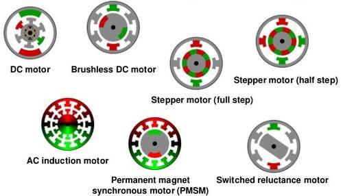
Each electric motor has some distinctive properties that determine its scope in which it is most beneficial. Synchronous, asynchronous, DC, collector, brushless, valve-inductor, step ... Why not, as is the case with internal combustion engines, invent a couple of types, bring them to perfection and put them and only them in all applications? Let's go through all types of electric motors, and at the end we will discuss why there are so many of them and which engine is the “best”.
DC motor (DPT)
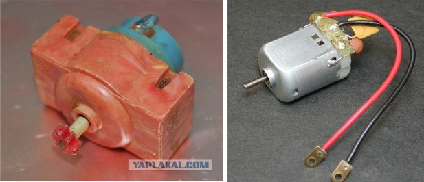
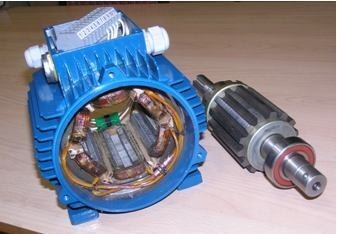
With this engine, everyone should be familiar from childhood, because it is this type of engine that is found in most old toys. Battery, two wiring to the contacts and the sound of a familiar buzz, inspiring to further design exploits. After all, everyone did that? I hope. Otherwise, this article is likely to not be interesting to you. Inside such an engine, a contact assembly is installed on the shaft - a collector, which switches the windings on the rotor depending on the rotor position. Direct current supplied to the motor flows through one or the other parts of the winding, creating a torque. By the way, without going far away, everyone, after all, was probably interested in - what were the yellow things on some DPT from toys, right on the contacts (as in the photo above)? These are capacitors — when the collector is working, due to commutation, the current consumption is pulsed, the voltage can also change irregularly, due to which the motor creates a lot of noise. They especially interfere if the DFT is installed in a radio-controlled toy. Capacitors just extinguish such high-frequency pulsations and, accordingly, remove interference.
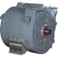
DC motors can be either very small in size (“vibration” in the phone) or rather large — usually up to megawatts. For example, the photo below shows a traction motor of an electric locomotive with a capacity of 810 kW and voltage of 1500V.
 Why don't DPTs be made more powerful? The main problem of all DPT, and in particular of a high capacity DPT, is the collector node. Sliding contact in itself is not a very good idea, and sliding contact on kilovolts and kiloampers is even more so. Therefore, designing a collector for high power DPT is an art, and at a power higher than a megawatt, it becomes too difficult to make a reliable collector (record - 12.5 MW).
In consumer quality, DFT is good for its simplicity in terms of manageability. Its moment is directly proportional to the armature current, and the rotational speed (at least idle) is directly proportional to the applied voltage. Therefore, before the onset of the era of microcontrollers, power electronics, and variable frequency ac drive, it was DPT that was the most popular electric motor for applications where it is necessary to adjust the rotational speed or torque.
It is also necessary to mention exactly how the excitation magnetic flux is formed in the DC motor, with which the armature (rotor) interacts and due to this a torque is generated. This flow can be done in two ways: by permanent magnets and an excitation winding. Permanent magnets are most often installed in small motors, and excitation winding in large ones. Excitation winding is another control channel. As the excitation winding current increases, its magnetic flux increases. This magnetic flux is included in both the motor torque formula and the emf formula. The higher the excitation magnetic flux, the higher the developed moment at the same armature current. But the higher and the EMF of the machine, which means that at the same supply voltage, the idling speed of the engine will be lower. But if you reduce the magnetic flux, then at the same supply voltage, the idling frequency will be higher, going to infinity when the excitation flux decreases to zero. This is a very important property of DPT. In general, I strongly advise studying the DPT equations - they are simple, linear, but they can be extended to all electric motors - the processes are similar everywhere.
Universal collector motor
Strangely enough, it is the most common electric motor in everyday life, the name of which is least known. Why did this happen? Its design and characteristics are the same as those of a DC motor, therefore the mention of it in drive textbooks is usually placed at the very end of the chapter on DC motor. In this case, the collector = DPT association so firmly sits in the head that not everyone comes to mind that the DC motor, in the name of which there is a “direct current”, can theoretically be included in the AC network. Let's see.
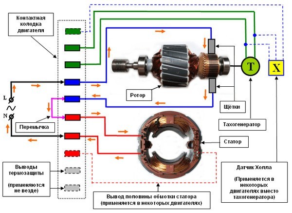
How to change the direction of rotation of the DC motor? Everybody knows this, it is necessary to change the polarity of the power of the anchor. And more? And you can also change the polarity of the excitation winding, if the excitation is done by winding, not by magnets. And if the polarity change and the anchor and the excitation winding? Correctly, the direction of rotation will not change. So what are we waiting for? We connect the armature and exciter windings in series or in parallel so that the polarity changes the same here and there, and then we insert into the single-phase AC network! Done, the engine will spin. There is only one small stroke that needs to be done: since an alternating current flows through the excitation winding, its magnetic core, unlike the true DFT, must be made of laminated to reduce the losses from eddy currents. And so we got the so-called "universal collector engine", which by design is a subspecies of the DPT, but ... works perfectly from both alternating and direct current.
This type of engine is most widely used in household appliances where rotational speed is required: drills, washing machines (not “direct drive”), vacuum cleaners, etc. Why is he so popular? Because of the ease of regulation. As in DPT, it can be adjusted by the voltage level, which is done by the triac (bi-directional thyristor) for the AC network. The control circuit can be so simple that it fits, for example, right in the “trigger” of the power tool and does not require either a microcontroller, or PWM, or a rotor position sensor.
Asynchronous motor
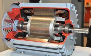 Even more common than collector motors, is an asynchronous motor. It is only distributed mainly in the industry - where there is a three-phase network. About the principle of his work a separate article was written. In short, its stator is a distributed two-phase or three-phase (less often multi-phase) winding. It connects to an AC voltage source and creates a rotating magnetic field. The rotor can be thought of as a copper or aluminum cylinder, inside of which there is an iron magnetic core. An explicit voltage is not supplied to the rotor, but it is induced there due to the alternating stator field (therefore, the motor in English is called induction). The resulting eddy currents in a short-circuited rotor interact with the stator field, resulting in a torque.
Why is an asynchronous motor so popular? It has no sliding contact, like a collector engine, and therefore it is more reliable and requires less maintenance. In addition, such a motor can be started from the AC network by “direct start” - it can be switched on by the switch “to the network”, as a result of which the engine will start (with a large starting current of 5-7 times, but acceptable). DPT of relatively high power cannot be switched on this way, a collector will burn from the inrush current. Also, asynchronous drives, unlike DCs, can do much more power - tens of megawatts, also due to the absence of a collector. In this case, the asynchronous motor is relatively simple and cheap.
Asynchronous motor is also used in everyday life: in those devices where it is not necessary to regulate the rotational speed. Most often this is the so-called "capacitor" engines, or, which is the same thing, "single-phase" asynchronics. Although in fact from the point of view of the electric motor, it is more correct to say “two-phase”, just one phase of the motor is connected to the network directly, and the second through a capacitor. The capacitor makes a phase voltage shift in the second winding, which allows you to create a rotating elliptical magnetic field. Typically, these engines are used in exhaust fans, refrigerators, small pumps, etc.
The minus of the asynchronous motor in comparison with DPT is that it is difficult to regulate it. An asynchronous motor is an AC motor. If an asynchronous motor simply lowers the voltage without lowering the frequency, then it will slightly slow down, yes. But it will increase the so-called slip (the lag of the rotation frequency from the frequency of the stator field), the losses in the rotor increase, because of which it can overheat and burn. You can think of it as controlling the speed of a passenger car solely by the clutch, giving full gas and turning on fourth gear. In order to properly regulate the frequency of rotation of an induction motor, it is necessary to regulate both the frequency and the voltage proportionally. And it is better to organize vector control at all, as was described in more detail in the last article . But for this you need a frequency converter - a whole device with an inverter, a microcontroller, sensors, etc. Until the era of power semiconductor electronics and microprocessor technology (in the last century), frequency control was exotic - there was nothing to do with it. But today an adjustable asynchronous electric drive based on a frequency converter is already standard de facto.
Synchronous motor
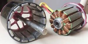
 About the principle of operation of the synchronous motor was also a separate article . Synchronous drives can be several subspecies - with magnets (PMSM) and without (with excitation winding and slip rings), with sinusoidal EMF or with trapezoidal (brushless DC motors, BLDC). This also includes some stepper motors. Before the era of power semiconductor electronics, synchronous machines were used as generators (almost all generators of all power plants are synchronous machines), and also as powerful drives for any serious load in the industry.
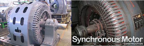
All these machines were performed with slip rings (you can see in the photo), of course, there is no talk about the excitation from permanent magnets at such powers. In this case, a synchronous motor, in contrast to an asynchronous one, has big problems with starting. If you turn on a powerful synchronous machine directly to a three-phase network, then everything will be bad. Since the machine is synchronous, it must rotate strictly with the frequency of the network. But during the time of 1/50 second, the rotor, of course, will not have time to accelerate from zero to the network frequency, and therefore it will simply jerk back and forth, since the moment will turn out to be alternating. This is called "synchronous motor not included in synchronism." Therefore, in real synchronous machines, asynchronous start-up is used — a small asynchronous start winding is made inside the synchronous machine and the excitation winding is short-circuited, simulating the asynchronous squirrel cage to accelerate the machine to a frequency approximately equal to the field rotation frequency, and after that the excitation with direct current the machine is drawn into synchronicity.
And if the asynchronous motor regulates the frequency of the rotor without changing the frequency of the field at least somehow, then the synchronous motor cannot be in any way. It either revolves from a frequent field, or falls out of synchronicity and stops with disgusting transients. In addition, a synchronous motor without magnets has contact rings - a sliding contact to transfer energy to the field winding in the rotor. From the point of view of complexity, this, of course, is not a collector of DPT, but it would still be better without a sliding contact. That is why, in industry, less capricious asynchronous drives are used for unregulated loads.
But that all changed with the advent of power semiconductor electronics and microcontrollers. They allowed to form for the synchronous machine any desired frequency of the field, tied through the position sensor to the motor rotor: to organize the valve mode of the engine (auto switching) or vector control. At the same time, the characteristics of the entire drive (synchronous machine + inverter) turned out to be the same as those of a DC motor: synchronous motors played in completely different colors. Therefore, starting somewhere in 2000, the “boom” of permanent-magnet synchronous motors began. At first, they shyly got out of the cooler fans as small BLDC engines, then got to the model aircraft, then climbed into the washing machines as a direct drive, into electric traction (segway, Toyota Prius, etc.), increasingly displacing the collector engine that is classical in such tasks. Today, permanent magnet synchronous motors take on more and more applications and are leaps and bounds. And all this - thanks to electronics. But what is better asynchronous synchronous motor, if we compare a set of converter + motor? And the worse? This question will be considered at the end of the article, and now let's take a look at several more types of electric motors.
Valve-inductor motor with self-excitation (VIEW CB, SRM)
He has many names. Usually it is briefly called a valve-inductor motor (VID) or a valve-inductor machine (VIM) or a drive (VIP). In English terminology, this is a switched reluctance drive (SRD) or motor (SRM), which translates as a machine with switchable magnetic resistance. But just below will be considered another subspecies of this engine, differing in the principle of action. In order not to confuse them with each other, the “usual” VIEW, which is discussed in this section, we call the “valve-inductor motor with self-excitation” or, briefly, the VIEW CB, which is called the “NPF VECTOR” company at the department of electric drives. emphasizes the principle of excitation and distinguishes it from the machine, discussed below. But other researchers also call it a SID with self-magnetisation, sometimes reactive AID (which reflects the essence of the formation of torque).
Structurally, this is the simplest motor and is similar in principle to some stepper motors. Rotor - gears. The stator is also notched, but with a different number of teeth. The easiest way to work the principle explains this animation:
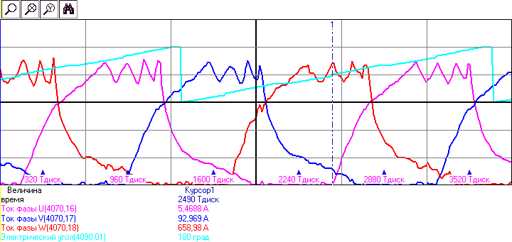
By applying a constant current to the phases in accordance with the current position of the rotor, it is possible to make the motor rotate. Phases can be a different amount. The shape of the current of the real drive for the three phases shown in the figure (current limit 600A):
However, for the simplicity of the engine has to pay. Since the motor is powered by unipolar current pulses, it cannot be switched directly on the network. A converter and a rotor position sensor are required. Moreover, the converter is not a classic (such as a six-key inverter): for each phase, the converter for SRD should have half bridges, as in the photo at the beginning of this section. The problem is that to reduce the cost of components and to improve the layout of the transducers, power switches and diodes are often not manufactured separately: usually, ready-made modules containing two keys and two diodes — the so-called racks — are usually used. And it is them that most often have to be put into the converter for the VIEW CB, half of the power switches simply leaving unused: a redundant converter is obtained. Although in recent years, some manufacturers of IGBT modules have released products designed specifically for SRD.
The next problem is torque ripple. Due to the jagged structure and pulsed current, the moment is rarely stable — most often it pulses. This somewhat limits the applicability of engines for transport - who wants to have a pulsating moment on the wheels? In addition, motor bearings do not feel very well from such pulses of pulling force. The problem is somewhat solved by special profiling of the phase current shape, as well as an increase in the number of phases.
However, even with these shortcomings, engines remain promising as an adjustable drive. Due to their simplicity, the motor itself is cheaper than the classic asynchronous motor. In addition, the engine is easy to make multi-phase and multisection, dividing the management of one engine into several independent converters that operate in parallel. This makes it possible to increase the reliability of the drive - shutting down, say, one of the four converters will not cause the drive to stop as a whole - the three neighbors will work for a while with a slight overload. For an asynchronous motor, such a focus cannot be done so simply because it is not possible to make the stator phases unrelated to each other, which would be controlled by a separate converter completely independently of the others. In addition, the appearance is very well regulated upwards from the main frequency. The rotor can be unwound without problems to very high frequencies.
We at the company NPF VECTOR, LLC have completed several projects based on this engine. For example, they made a small drive for hot water pumps , and also recently completed the development and debugging of a control system for high-capacity (1.6 MW) multiphase redundant drives for processing plants of ALROSA . Here is a 1.25 MW machine:
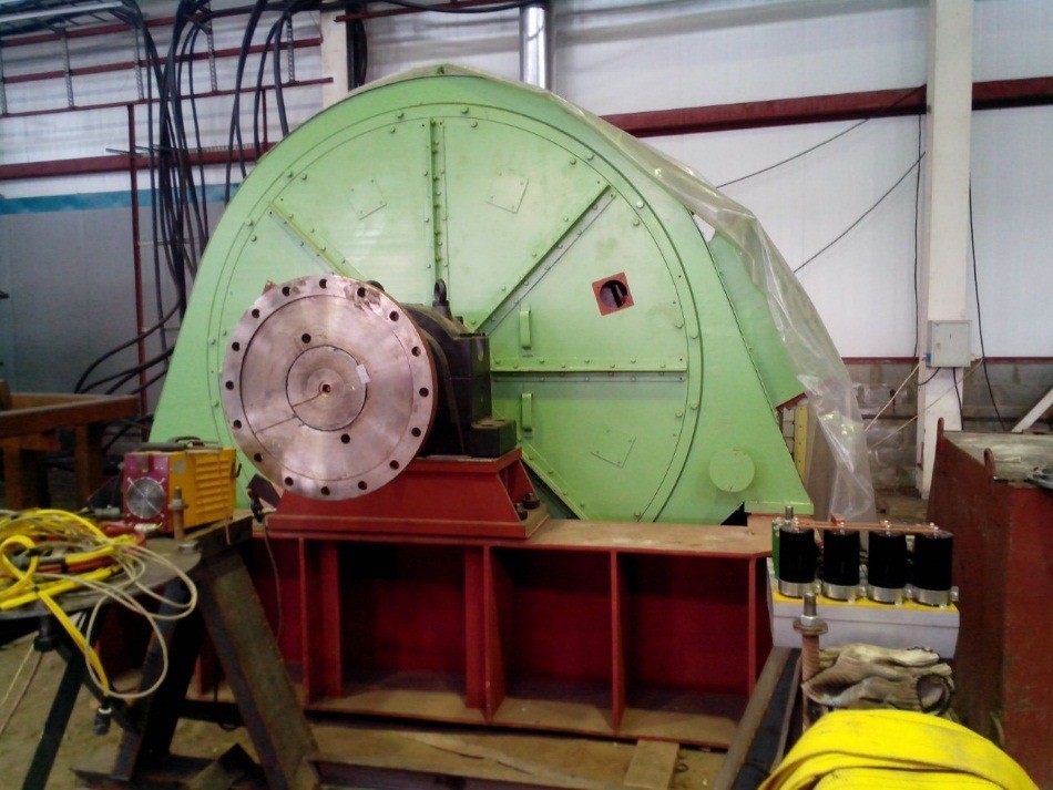
The entire control system, controllers and algorithms were made in NPF VECTOR LLC, power converters were designed and manufactured by LLC NPP TsIKL +. The customer of the work and the designer of the engines themselves was the company LLC MIP "Mechatronica" YURGTU (NPI) ".
Valve-inductor motor with independent excitation (type HB)
This is a completely different type of engine, differing in the principle of operation from the usual VIEW. Historically known and widely used valve-inductor generators of this type, used on airplanes, ships, rail transport, but for some reason, they are little involved in this type of engines.
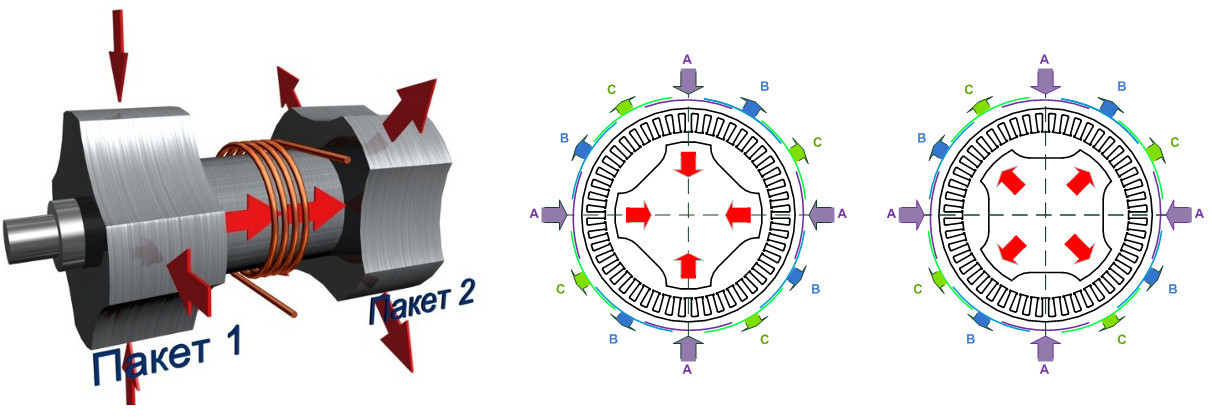
The figure schematically shows the geometry of the rotor and the magnetic flux of the excitation winding, and also shows the interaction of the magnetic fluxes of the stator and the rotor, while the rotor in the figure is set to a consistent position (the moment is zero).
The rotor is assembled from two packages (from two halves), between which an excitation winding is installed (in the figure it is shown as four turns of copper wire). Despite the fact that the winding hangs "in the middle" between the halves of the rotor, it is attached to the stator and does not rotate. The rotor and stator are made of laminated iron, there are no permanent magnets. The stator winding is distributed three-phase - like a conventional asynchronous or synchronous motor. Although there are variants of this type of machine with a concentrated winding: teeth on the stator, like the SRD or BLDC motor. The stator windings cover both rotor packages at once.
The principle of operation can be simplified as follows: the rotor tends to turn to a position in which the directions of the magnetic flux in the stator (from the currents of the stator) and the rotor (from the excitation current) coincide. In this case, half of the electromagnetic moment is formed in one package, and half in the other. On the stator side, the machine implies a bipolar sinusoidal power supply (EMF sinusoidal), the electromagnetic moment is active (polarity depends on the sign of the current) and is formed by the interaction of the field created by the excitation winding with the field created by the stator windings. By the principle of operation, this machine is different from the classic stepper and SRD engines, in which the moment is reactive (when the metal bar is attracted to the electromagnet and the sign of the force does not depend on the sign of the current of the electromagnet).
From the point of view of control, HBV is equivalent to a synchronous machine with slip rings. That is, if you do not know the design of this machine and use it as a “black box”, then it behaves almost indistinguishable from a synchronous machine with a field winding. You can do vector control or autocommutation, you can weaken the excitation flow to increase the rotational speed, you can amplify it to create more moment - all as if it were a classic synchronous machine with adjustable excitation. Only the HB VIEW does not have a sliding contact. And does not have magnets. And the rotor in the form of a cheap iron blanks. And the moment does not pulsate, unlike SRD. For example, here are the sinusoidal currents TYPE HB during the operation of vector control:

In addition, the TYPE of HB can be created multiphase and multisection, in the same way as it is done in the TYPE ST. In this case, the phases are uncoupled by magnetic fluxes and can operate independently. Those. it turns out as if several three-phase machines in one, each of which is joined by its own independent inverter with vector control, and the resulting power is simply summed. Coordination between the transducers does not require any - only the general setting of the rotational speed.
There are also disadvantages to this engine: it cannot spin directly from the network, since, unlike the classical synchronous machines, the HLT view does not have an asynchronous starting winding on the rotor. In addition, it is more complex in construction than the usual type of SV (SRD).
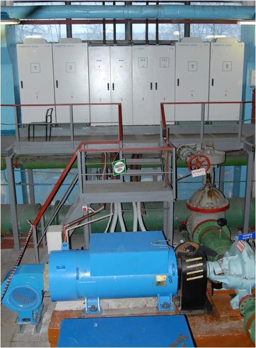
On the basis of this engine, we also made several successful projects. For example, one of them is a series of pump drives and fans for district heating plants of Moscow with a capacity of 315-1200 kW ( reference to the project ). These are low-voltage (380V) TYPE HV with redundancy, where one machine is “split” into 2, 4 or 6 independent three-phase sections. Each section has its own type converter with vector sensorless control. Thus, it is possible to easily increase power based on the same type of construction of the converter and the motor. In this case, part of the converters is connected to one input of the district heating station, and part to the other. Therefore, if there is a “power supply mink” on one of the power supply inputs, then the drive does not rise: half of the sections operate briefly in the overload until the power is restored. As soon as it is restored, rested sections are automatically entered into work on the fly. In general, probably, this project would deserve a separate article, so for now I’ll finish about it by inserting a photo of the engine and converters:
Conclusion: What is the best electric motor?
Unfortunately, two words are not enough. And the general conclusions about the fact that each engine has its advantages and disadvantages - too. Because not considered the most important qualities - weight and dimensions of each and types of machines, the price, as well as their mechanical characteristics and overload capacity. Let's leave the unregulated asynchronous drive to turn its pumps directly off the mains, there are no competitors for it. Let's leave the collector machines to turn the drills and vacuum cleaners, then with them in the simplicity of regulation it is also difficult to contend.
Let's consider an adjustable electric drive, the mode of operation of which is long. Collector machines are immediately excluded from competition due to the unreliability of the collector node. But there are still four left - synchronous, asynchronous, and two types of valve-inductor. If we are talking about the drive of a pump, a fan and something similar that is used in industry and where the weight and dimensions are not particularly important, then synchronous machines drop out of the competition. Excitation winding requires slip rings, which is a capricious element, and permanent magnets are very expensive. Competing options remain asynchronous drive and valve-inductor motors of both types.
Experience shows that all three types of machines are successfully used. But - an asynchronous drive cannot (or is very difficult) to partition, i.e. break a powerful machine into several low-powered ones. Therefore, to ensure a high power asynchronous converter, it is required to make it high-voltage: after all, power is, if roughly, the product of voltage and current. If for a sectionable drive we can take a low-voltage converter and set them up a few, each for a small current, then for an asynchronous drive, the converter should be one. But do not do the same converter at 500V and current 3 kiloampere? This wires are needed with arm thick. Therefore, to increase the power, the voltage is increased and the current is reduced. A high voltage converter is a completely different class of problem. You can’t just take 10kV power switches and make them a classic 6-key inverter, as before: there are no such keys, and if they are, they are very expensive. Inverter make multi-level, on low-voltage switches connected in series in complex combinations. Such an inverter sometimes pulls up a specialized transformer, optical key management channels, a complex distributed control system working as one unit ... In general, everything is complicated for a powerful asynchronous drive. At the same time, the valve-inductor drive can, by sectioning, “delay” the transition to a high-voltage inverter, allowing the drive to be made up to a few megawatts of low-voltage power, made according to the classical scheme. In this regard, the VIPs become more interesting asynchronous drive, and even provide redundancy. On the other hand, asynchronous drives have been operating for hundreds of years, engines have proven their reliability. VIPs just make their way. So here you need to weigh a lot of factors in order to choose the most optimal drive for a specific task.
But everything becomes even more interesting when it comes to transport or small devices. There it is no longer possible to blithely treat the mass and dimensions of the electric drive. And there already it is necessary to look at synchronous machines with permanent magnets. If you look only at the power parameter divided by mass (or size), then synchronous machines with permanent magnets are out of competition. Individual copies can be many times smaller and lighter than any other "non-magnetic" AC drive. But there is one dangerous misconception, which I will now try to dispel.
If a synchronous machine is three times smaller and lighter - this does not mean that it is better suited for electric traction. It's all about the lack of adjustment of the flow of permanent magnets. The flow of magnets determines the emf of the machine. At a certain frequency of rotation, the EMF of the machine reaches the supply voltage of the inverter and a further increase in the rotational speed becomes difficult. The same goes for raising the moment. If you need to realize a greater moment, in a synchronous machine you need to increase the stator current - the moment will increase proportionally.But it would be more effective to increase the excitation flow - then the magnetic saturation of iron would be more harmonious, and the losses would be lower. But again, we can not increase the flow of magnets. Moreover, in some designs of synchronous machines, the stator current cannot be increased beyond a certain value — the magnets can demagnetize. What is the result?A synchronous machine is good, but only at a single point - at the nominal one. With rated speed and rated torque. Above and below - everything is bad. If you draw it, you get this characteristic of frequency from moment (red):

, – . , , 60. – , – .. «» «» . , – ( d ), , . Everything. , 60. . Those. , , 10/ 60 , 150/. : ( , . ), 50-60/.
What does this mean? ? , , - . Like this:
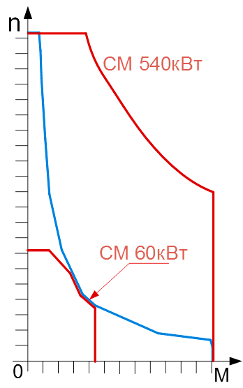
, . Those.so that the machine can simultaneously develop a large moment and work at a high frequency of rotation. As you can see from the figure ... the installed capacity of such a machine will no longer be 60 kW, but 540 kW (can be calculated by division). Those. In an electric car with a 60kW battery, you will have to install a synchronous machine and an inverter on 540kW, just to “go through” at the required torque and speed.
, , . 540 60. , «» . , ( ), , . , , . , « , ». «» . , — , , — ..
, . , , 30/ ( ?). : , – , (). – , . , , .
, , : . , . ( ) (, ..). ?
( ) , . . : -, – . . ( ) . – , 4 , , , . – . , . . , . – «» , ( ). . «» — ( ), . … .
, Model S. … ( , , , ). … . , «» , 540, 300. , - . Those. «» , - . . «» , 100 , , , ( 300), .
And now VIPs. What can they do? What is their traction characteristic? I can’t say for sure about TYPE OF SV - it’s a non-linear motor by its principle of operation, and its mechanical characteristic can vary greatly from project to project. But in general, it is most likely better than an asynchronous motor in terms of approaching the desired traction characteristic with constant power. But about the type of HB I can say more, since we at the company are engaged in it very closely. Do you see the desired traction characteristic in the figure above, which is painted in blue, to which we want to strive? This is actually not just the desired characteristic. This is a real traction characteristic, which we have taken on points according to the torque sensor for one of the TYPE HB. Since the TYPE of HB has an independent external excitation, its qualities are closest to the DPT HB,which can also form such a traction response by controlling the excitation.
So what?View HB - the perfect machine for traction without a single problem? Not really. He has a lot of problems too. For example, its excitation winding, which "hangs" between the stator packets. Although it does not rotate, it is also difficult to remove heat from it - the situation is almost like a rotor of an asynchronous, only slightly better. You can, if necessary, "throw" the cooling tube from the stator. The second problem is the overestimated weight and dimensions. Looking at the picture of the rotor VIEW HB, one can see that the space inside the engine is not used very efficiently - only the beginning and the end of the rotor “work”, and the middle is occupied by the excitation winding. In an asynchronous motor, for example, the entire length of the rotor, all the iron "works." The complexity of the assembly - shove the excitation winding into the rotor packages must also be managed (the rotor is collapsible, respectivelythere are problems with balancing). Well, just the weight and size characteristics so far are not very outstanding compared to the same Tesla asynchronous motors, if you put traction characteristics on each other.
And there is also a common problem with both types of VIEW. Their rotor is a steamer wheel. And at high frequencies of rotation (and a high frequency is needed, so high-frequency machines with the same power are less slow), the loss from mixing the air inside becomes very significant. If up to 5000-7000 rev / min. VIEW can still be done, then at 20,000 rev / min it will turn out to be a big mixer. But an asynchronous motor for such frequencies and much higher can be done at the expense of a smooth stator.
So what is the best result for electric traction? Which engine is the best?
I have no idea. . . – , - , . . , . – , – . – , . , - . And so on and so forth…
.
UPD:
, , , , .
1. — , , ( ) . , . , — .
2. . — , SRD gif , , — SRD. , . .
3. , , SRD — . , «» , () : . — (). , «» — . . , .
Source: https://habr.com/ru/post/371749/
All Articles