Smart home start
The idea of creating a smart home (UD) originated in the head long before the appearance of your own house (apartment). From time to time I studied articles about the smart home, looked for various solutions online and tried them on my own vision of the smart home. Gradually, a picture of the future project emerged in my head. And when the long-awaited moment came, the apartment was acquired, I began to put my ideas into practice. I am a practitioner by nature, it’s easier for me to start immediately doing something in the gland without writing, unnecessary words, plans and calculations on paper, so the whole project was in my head and constantly adjusted.
The choice was made at 99% in the direction of wired devices, plus all devices should be as low as possible. Initially I planned to do everything on microcontrollers, but after learning about the existence of the Arduino, the choice fell on her, because simplified manufacture of end devices, it was not necessary to make the board yourself.
During the repair phase, a twisted pair cable was laid in all possible directions - lighting, windows, doors, radiators, water meters, heat meters, an electric meter, intercom, TV, computer, projector, air conditioning, access shield, motion sensors, balcony, all switches and sockets ...
')
Power wiring was redone. I refused the switchgear, and all the wiring from each chandelier, switch, sockets are tightened instead of installing an electrical panel. Additionally, the power wiring is stretched to each window, to power the controllers and power supply for roller blinds. In total, the two-room apartment took about 1 kilometer of various wires.
The heart of the system is the server based on the Asus EeeBox nettop, on which iobroker runs . All controllers communicate with the server using the MQTT protocol.
In each window there is a room controller built on the Arduino UNO + Ethernet Shield W5100, each of which collects the following information:
The lighting is controlled by a separate controller built on the Arduino Mega + Ethernet Shield W5100.
The switches are the usual Schneider Electric reversible switches from the Unica series with a redesigned backlight for 5V. The backlight is powered by a field effect transistor from the PWM lighting controller (CO).
Switches commute 12V which through the divider arrive at the input of the CO. The KO program inverts the output state when the switch is switched, i.e. if the light is on, switching the switch will turn off the light and vice versa. The disadvantage of this decision is that the switches do not have the on / off position, and one of the advantages is the easy organization of the emergency mode, in which the switches switch the lighting relay (Finder) directly bypassing the CO.
In the bathroom, in addition to the usual switch, there is a visitor counter on the IR sensors. If visitors are greater than 0, the light is on.
Additionally, management and control of individual devices is organized:
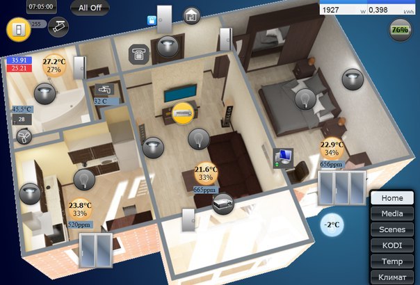
The management of the DD is organized through the web from both a computer and a phone or tablet. Plus, the management of voice commands via the phone using the Tasker application is organized.
PS This is the first iteration of my DD and not all is completed yet. If some moments will be interesting to readers, then I will reveal in more detail in the following articles.
Part Two - Bathroom Visitor Counter
The choice was made at 99% in the direction of wired devices, plus all devices should be as low as possible. Initially I planned to do everything on microcontrollers, but after learning about the existence of the Arduino, the choice fell on her, because simplified manufacture of end devices, it was not necessary to make the board yourself.
During the repair phase, a twisted pair cable was laid in all possible directions - lighting, windows, doors, radiators, water meters, heat meters, an electric meter, intercom, TV, computer, projector, air conditioning, access shield, motion sensors, balcony, all switches and sockets ...
')
Power wiring was redone. I refused the switchgear, and all the wiring from each chandelier, switch, sockets are tightened instead of installing an electrical panel. Additionally, the power wiring is stretched to each window, to power the controllers and power supply for roller blinds. In total, the two-room apartment took about 1 kilometer of various wires.
Electrical board
The heart of the system is the server based on the Asus EeeBox nettop, on which iobroker runs . All controllers communicate with the server using the MQTT protocol.
In each window there is a room controller built on the Arduino UNO + Ethernet Shield W5100, each of which collects the following information:
Controller in the window frame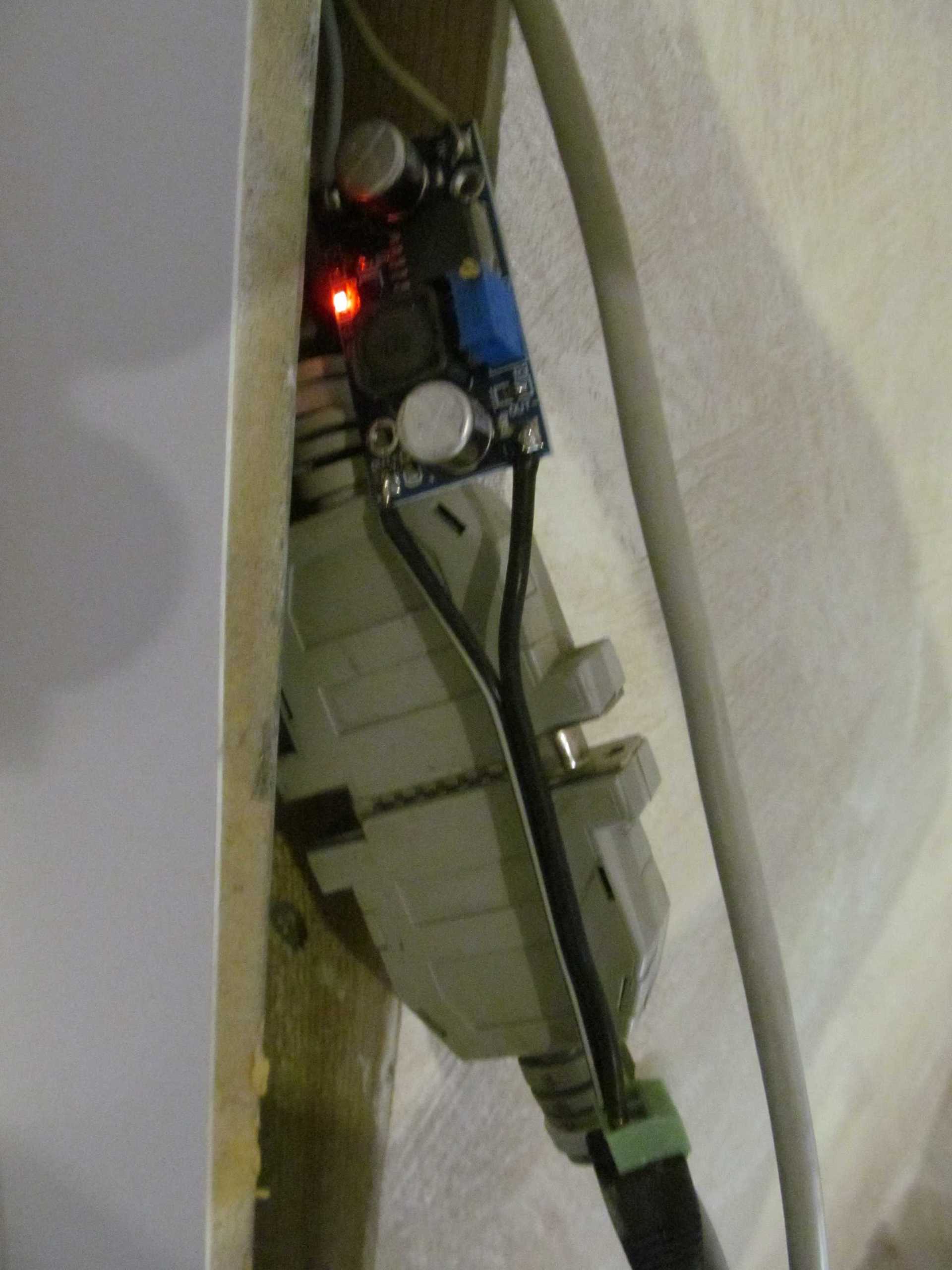

- radiator temperature (DS18b20)
- room temperature and humidity (DHT22)
- light level (photoresistor)
- CO sensor (MQ7, it is planned to replace it with a more reliable sensor)
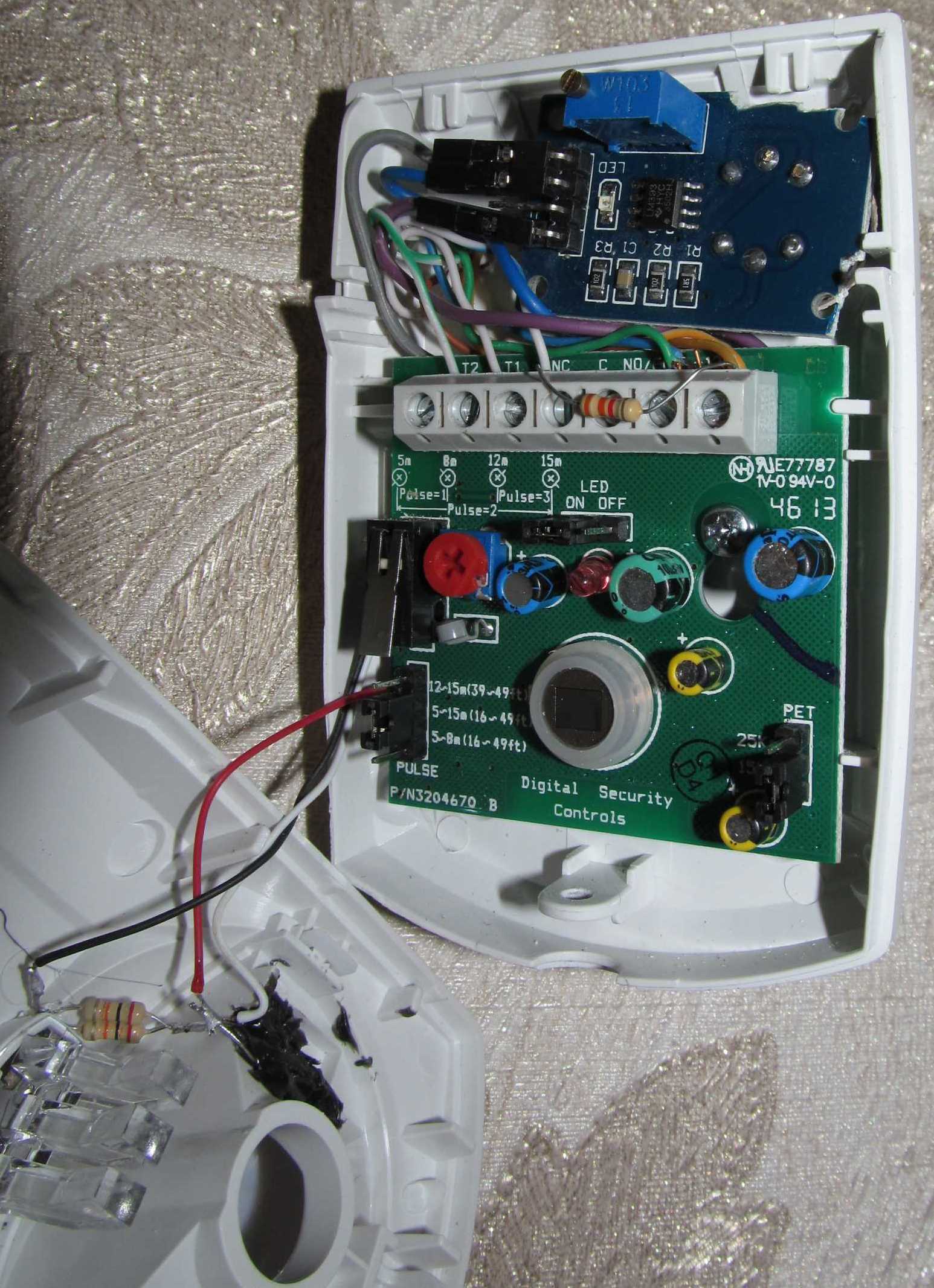
- volume sensors (DSC LC-100PI, converted to 5V power supply, which has a built-in light sensor and CO sensor)Volume sensor
- in the bedroom and living room, in addition, temperature sensors DS18b20, which are installed inside the KIP-125 intake valves
- servo-drive control (SG90) which is installed on the KIP-125 intake flap valvesServo valve KIP-125

- open window sensor (reed switch)
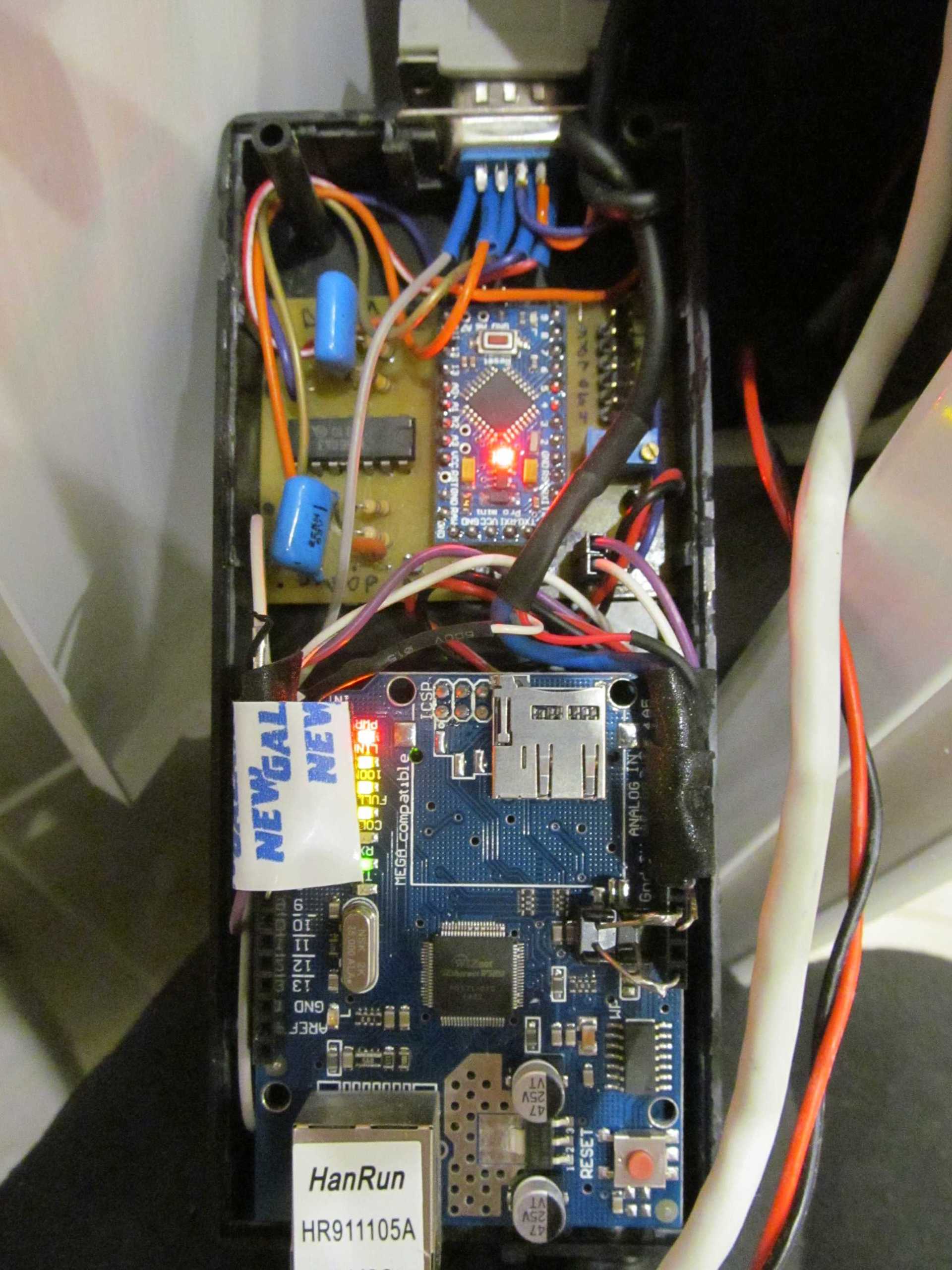
The lighting is controlled by a separate controller built on the Arduino Mega + Ethernet Shield W5100.
Lighting Controller Assembly
The switches are the usual Schneider Electric reversible switches from the Unica series with a redesigned backlight for 5V. The backlight is powered by a field effect transistor from the PWM lighting controller (CO).
Switch
Alteration of the backlight switch under 5V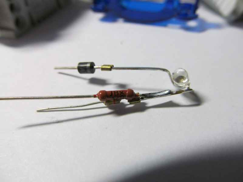
Switches commute 12V which through the divider arrive at the input of the CO. The KO program inverts the output state when the switch is switched, i.e. if the light is on, switching the switch will turn off the light and vice versa. The disadvantage of this decision is that the switches do not have the on / off position, and one of the advantages is the easy organization of the emergency mode, in which the switches switch the lighting relay (Finder) directly bypassing the CO.
Emergency mode fee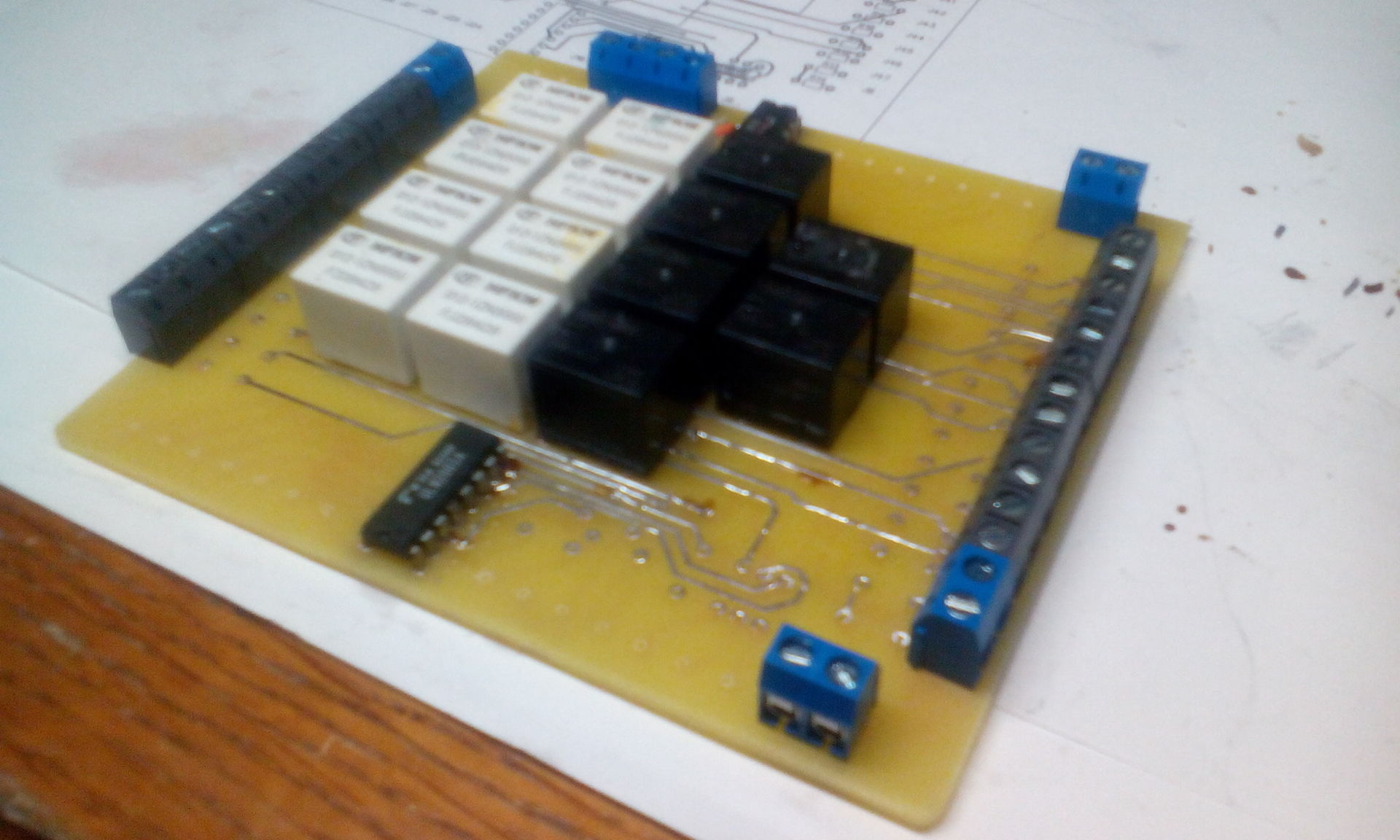
Lighting Control Relay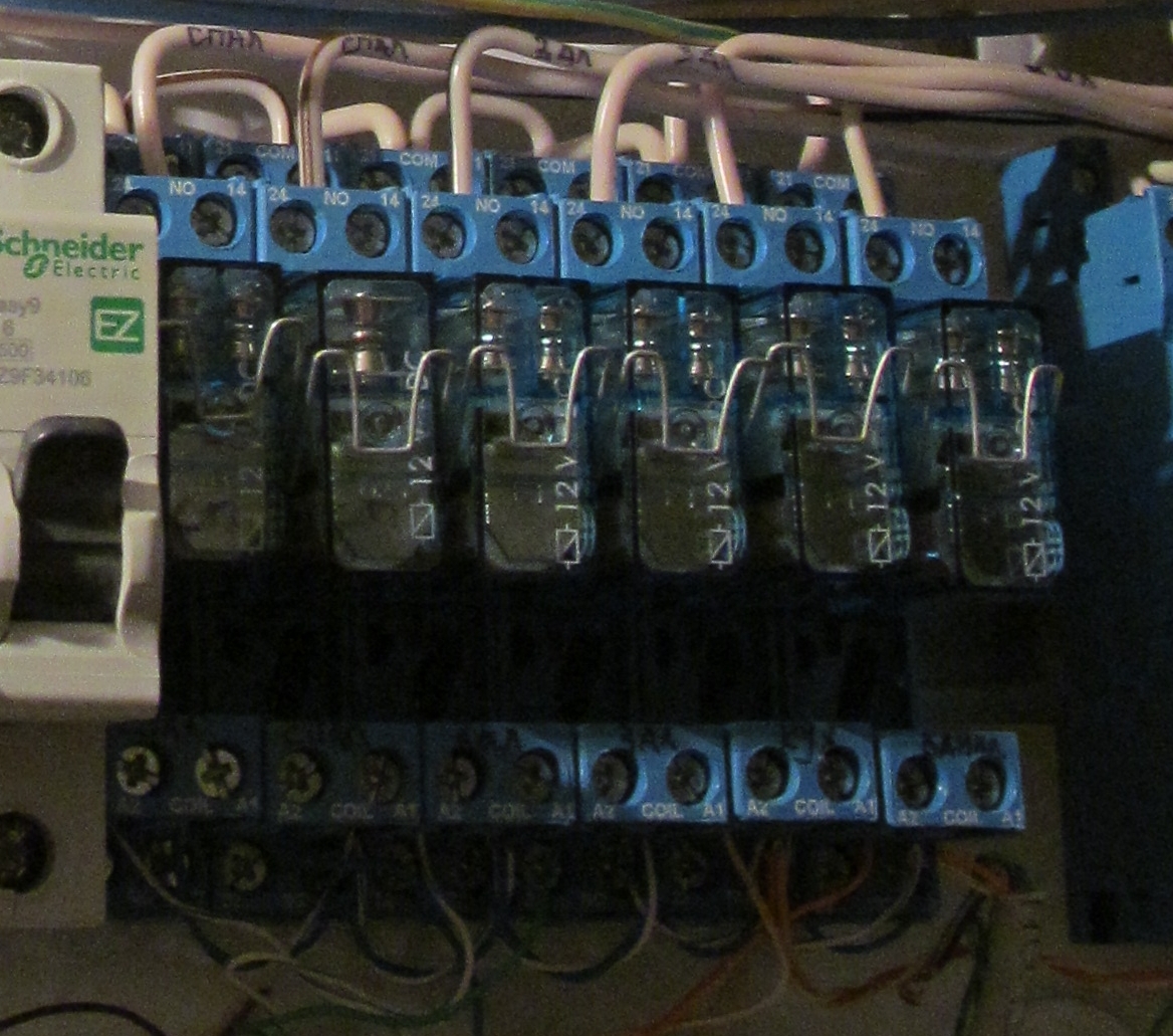
In the bathroom, in addition to the usual switch, there is a visitor counter on the IR sensors. If visitors are greater than 0, the light is on.
Visitor counter to the bathroom
Additionally, management and control of individual devices is organized:
- The TV (LG, not smart) is not controlled via Ethernet, but is controlled via RS232. To control the set Arduino UNO + Ethernet Shield W5100.Spoiler header

- A projector (BENQ) is similar to a television.
- The ONKYO receiver is controlled both via Ethernet and RS232, iobroker has a driver to control ONKYO receivers via ethernet, so it works out of the box.
- intercom control (Cyfral, coordinate). The opening of the access door (on the relay) and the monitoring of the doorphone call are organized, when the doorphone calls on the TV, the image from the access camera is turned on, a message is received on the phone that contains a link to open the door.Control intercom


- water heater control (Termex). Management and control is organized on Arduino pro mini + NRF24, powered by a built-in heater management board. Implemented on, off, switching the heating mode and setting the temperature. Switching taps only with your hands, hot water is not often turned off, and spend ~ 5 tr. There is no desire for cranes with a drive, so it does not strain. How to turn off the hot water, I want to conduct an energy efficiency experiment, maintain the set water temperature around the clock, or turn off the water heater or lower the set temperature for the night and absence.Water heater management from the web of the muzzle

- leakage protection system management (Aquastorozh). Organized on a bunch of Arduino pro mini + NRF24.Aquastorozhom management

- water consumption meters (meters with pulse output). I count impulses Arduino pro mini and give data on the UART controller “bath” (Arduino UNO + Ethernet Shield W5100).Water meter
- electricity meter (with pulse output). I consider pulses as a water meter.
The management of the DD is organized through the web from both a computer and a phone or tablet. Plus, the management of voice commands via the phone using the Tasker application is organized.
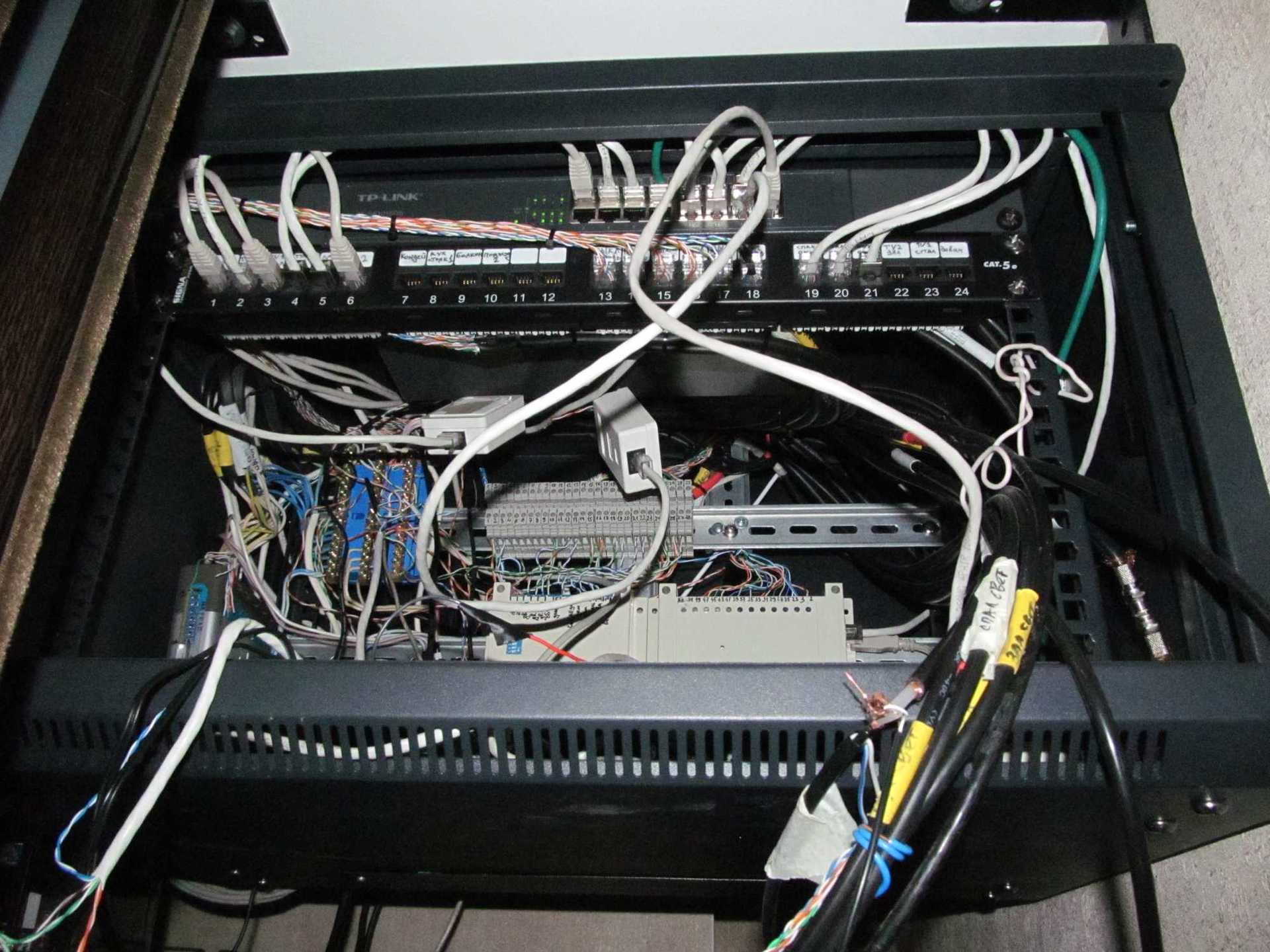
Automation Cabinet
Work chaos.
Some more photos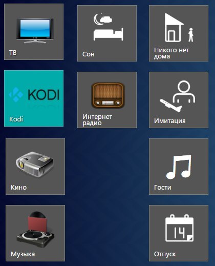
PS This is the first iteration of my DD and not all is completed yet. If some moments will be interesting to readers, then I will reveal in more detail in the following articles.
Part Two - Bathroom Visitor Counter
Source: https://habr.com/ru/post/371685/
All Articles