How our optical dividers are “baked” (part two)
Planar dividers PLC (Planar Lightwave Cirquit)
In the last review, the production process of welded dividers was shown a little more than completely. But there is another way to "divide" the flow of light in the fiber - planar dividers, in other words, PLC (Planar Lightwave Cirquit). In theory, this is far from new, although previously, due to the high price, PLCs were used only in the most expensive, multifiber projects. However, progress does not stand still ...
Naturally, each product has its advantages and disadvantages, and science seeks to reduce the second aspect to a minimum. So what disadvantages of welded dividers prompted the world of science and technology to new developments? They are not difficult to call:
- first, the relatively high level of insertion loss;
- secondly, the reduction in the uniform distribution of optical power across the channels as a result of increasing cascades;
- thirdly, losses in reflection, any, even perfect welding is a potential problem.
Accordingly, they are relieved of the above-mentioned drawbacks of the PLC. But not only, there are several significant advantages:
')
- PLCs operate in the wavelength range of 1260 ... 1650nm .;
- Extended operating temperature range (-45 .... + 85, for welded: -40 ... + 75);
- Significant reduction in the dimensions of the product.
Like many semiconductor products, this product fell under the criterion of "price - a function of the quantity of products." Thus, over the past few years, the cost of such dividers has declined substantially, rising almost at the same level with welded ones, and in positions with a large division ratio (1x8, 1x16, 1x32, 1x64), the cost of PLC is noticeably lower than welded.
For example, the planar divider SNR-PLC-1x32-SC / APC costs around $ 110, and its “welded” analog — the SNR-CPC-1x32-SC / APC — is as much as $ 320. However, this does not prevent not-too-competent purchasers from ordering the “usual” - at almost three times the price. On devices with a smaller division ratio, the difference is, of course, smaller. Eight-channel PLCs cost about 33 bucks versus almost 80 for “welded”, and on dual-channel PLC everything is generally determined by the price of the connectors. So the advantages of “welded” remained only in the flexibility of controlling the power dividing factors, but, firstly, this feature is hardly applicable to the transfer of PON data, and secondly, the PLC has significant advances.
As for the technology of manufacturing PLC dividers, the main component of the whole process is ... a semiconductor chip.
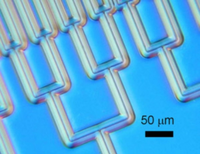
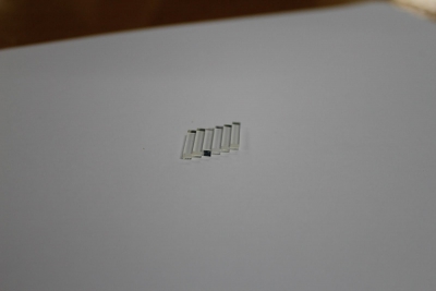
(This is how the channel system looks like under a microscope)
The production of PLC chips consists of several stages. The first is to apply a reflecting layer to the substrate, on which the waveguide material is applied, which is etched. The result of the etching process is a channel-waveguide system that fully displays the fission scheme. The next stage - the planar waveguide system is covered with a reflective shell layer. The required number of branches is achieved by dividing the main input optical channel and its subsequent branches.
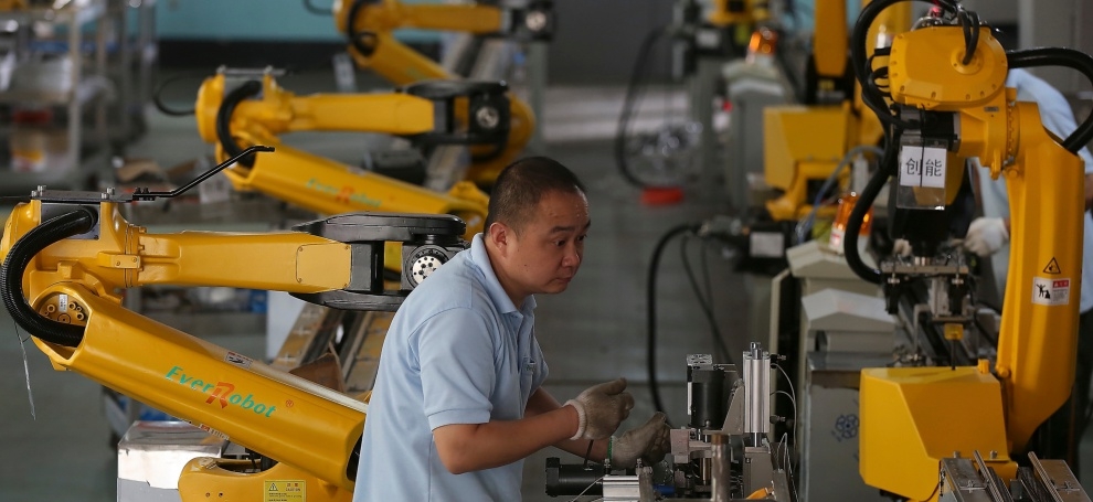
As a rule, specialized enterprises (about a couple dozen of them in the world), which make only micro-optics, are engaged in the production of such chips. All existing plants that produce PLC-dividers as final products, buy ready-made chips (mainly from South Korea) and mount them in the case.
If someone is interested in more deeply questions about the use of micro-optics, then we can cite patents on various ways of applying them:
1. Optical module.

2. Two-dimensional micro arrays in silica-onsilicon planar light wave circuit technology.
3. Optical pulse compressor based on integrated planar lightwave circuit.
4. Planar lightwave circuit and tunable laser device having the same.
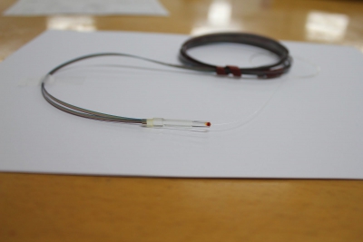
Making a divider from a chip
1. Materials
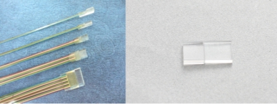
PLC chip:
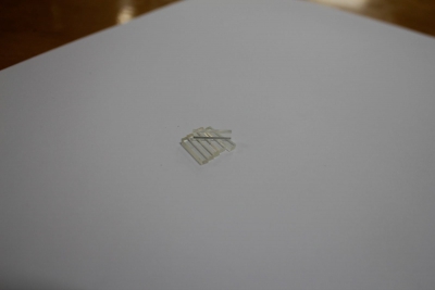
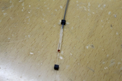
Under the PLC microscope, the chip looks like this:

In two projections like this:
Pigtail with ribbon cable:


Pigtail with input fiber:
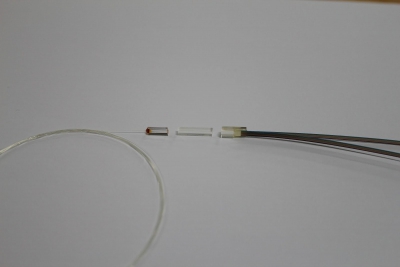
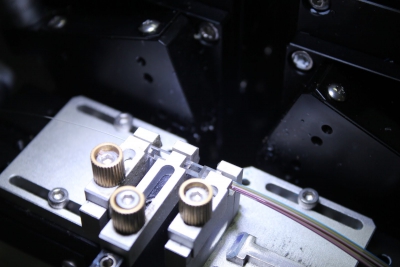
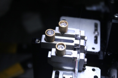
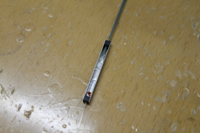
Structurally, it looks like this:

Installation looks like this:
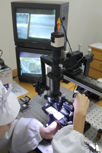
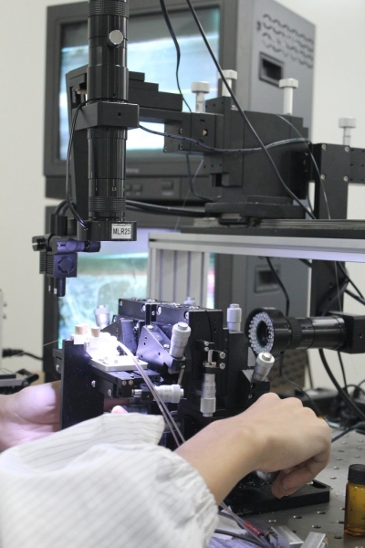
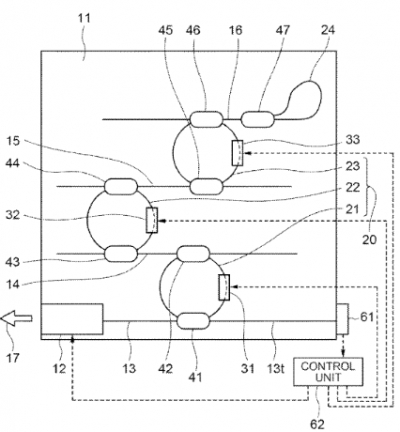
Special installation with high zoom cameras. With its help, the adjustment of 3 components of the PLC divider: PLC chip and two pigtails:
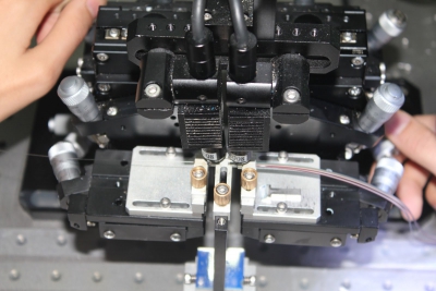
Here are the 2 joints in 2 planes:
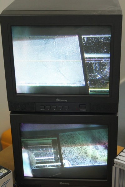
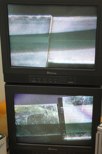
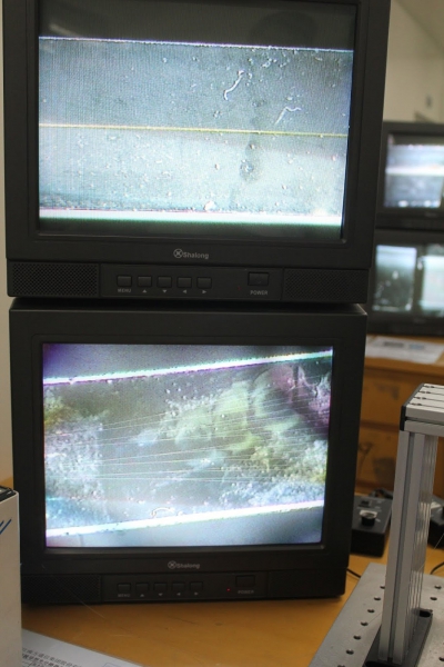
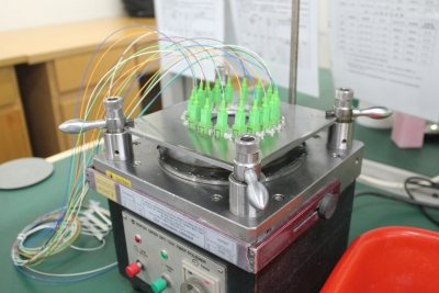
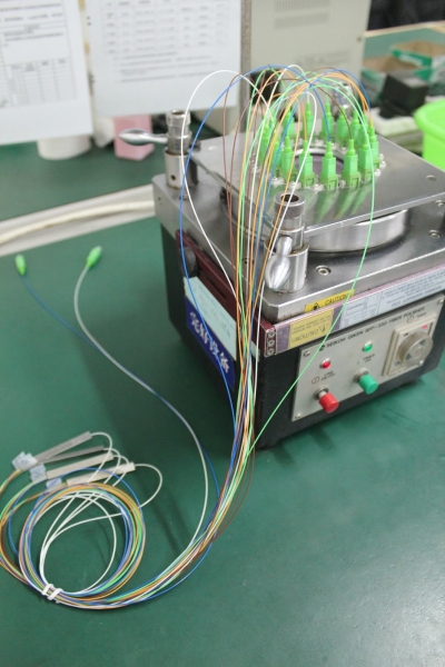
All installation is carried out under the control of measuring equipment:
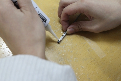
After alignment, gluing is performed:
After gluing the blank is ready. It must be mounted in a metal mini-body.
It happens like this:
We put on rubber pads on each of the ends of the divider.
And placed in a metal case of the appropriate size.
Secure with glue.
And mount the cover (on which the laser is pre-applied S / N).

If the divider is necessary terminated, then we act as in the case of welded dividers: glue and polish the connectors.
How can you be sure - just a miracle of nano-technology ... When will Rosnano start doing at least that?
Comparison of PLC and welded dividers
General optical characteristics
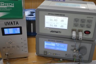
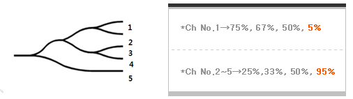
Measurements were carried out on welded dividers 1x2, 1x8 and PLC 1x8 in the wavelength range 1250-1650.
Figure 1 shows the insertion loss (9.3dB) of a standard 1 × 8 PLC divider. Also shown are the maximum insertion loss (10.3dB), including the loss in the “water peak” region in the zone from 1360 to 1460 nm, as well as an excellent uniformity indicator equal to 1dB.
Given that the reference values of the insertion loss and the uniformity index are 9.8dB and 0.5dB, it can be said with confidence that PLC dividers give good indicators of fundamentally important physical parameters.
Below is the result of a 1 × 2 welded divider study. As seen in the image, the level of maximum insertion loss here is much lower (3.5dB), while the value of the uniformity index remains the same (1.0dB). But this is a 1 × 2 divider, not 1 × 8.
As described above, cascading is used for the production of welded dividers 1x4, 1x8, which directly affects the change in the optical characteristics of the product. So, in the 3rd section, the insertion loss of a welded divider 1 × 8 is shown, the maximum level of which is 10.8dB, and the uniformity index is 3 dB, which differs significantly from the readings of the divider PLC.

TDL (Dependence of the insertion loss on temperature change)
In a 1x2 welded divider, this parameter is ± 0.15dB in the temperature range from -5 to + 75, taking into account that we compare the 1x8 division ratios and that the 1x8 welded divider is obtained by cascading 1x2 dividers, we must multiply 0.15x3 = 0 45
The operating temperature range of the PLC divider is -40 to +85 ° C. When working in this range, the coefficient of dependence of the insertion loss on temperature is ± 0.25 dB; when operating in the range from -5 to + 75 ° C, it is ± 0.15 dB.
PDL (Dependence of the insertion loss on polarization changes)
In PLC dividers, this parameter is 0.2-0.3 dB, and also, as in the case with a temperature coefficient, this value does not change depending on the split ratio of 1x8, 1x16, etc.
In the 1x8 welded divider, the dependence of the insertion loss on the polarization is 0.1-0.15 dB regardless of the split ratio (1x4, 1x8 ...).
Reliability
The risk of device failure is usually calculated from a parameter called FIT (Failure In Time). For a welded divider, this parameter is small, but with an increase in the division ratio, the number of cascades grows, and with each cascade, FIT will increase each time by the value of the new cascade.
As for the PLC dividers, for them there are only 2 critical parameters for reliability - this is the entry point and exit point.
Instead of an epilogue
Science and industry do not stand still. In South Korea, PLC chips with an uneven division ratio are already being produced. So, in the near future, we should expect the appearance of 1x3, 1x7 and other PLC dividers with different division ratio between the arms. Apparently after this, welded (FBT) dividers can become as archaic as Token Ring, FDDI, etc. etc.
Source: https://habr.com/ru/post/371203/
All Articles