Electrostatic air purifier do it yourself. Part 1 - principles of work
At some point in time, my enthusiasm for building a domestic electrostatic air purifier (electrostatic precipitator) kindled. Surprisingly, I was not able to find suitable materials in the network in this area, which prompted me to write this article.
In the first part I suggest to get acquainted with the principles of operation of these devices, and in the next - to build a full-fledged cleaner with your own hands.
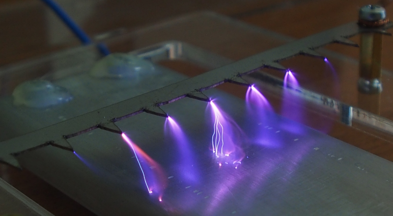
In the photo, corona discharge used in electrostatic air purifiers
Sources of dust and affordable household air purifiers
Uniform electric field and electrical air breakdown
Inhomogeneous electric field and corona discharge in air
Principle of electrical air cleaning
Electrode Electrostatic Filter Systems
Conclusion
Sources
')
Airborne fine dust particles PM10 and PM2.5 are able to penetrate into our body when breathing: bronchi, lungs, and even enter the bloodstream. According to the World Health Organization (WHO) , air pollution with such particles poses a serious health hazard: exposure to air with a high content of such particles (PM2.5 exceeding the average annual concentration of 10 µg / cubic meter and daily average 25 µg / cubic meter; exceeding the PM10 average annual 20 μg / m 3 and average daily 50 μg / m 3) increases the risk of respiratory diseases, diseases of the cardiovascular system and some oncological diseases, pollution has already been assigned to Group 1 of carcinogens . Highly toxic particles (containing lead, cadmium, arsenic, beryllium, tellurium, etc., as well as radioactive compounds) are dangerous even at low concentrations.
The easiest step to reducing the negative effects of dust on the body is to install an effective air purifier in a sleeping room, where a person spends about a third of the time.
Major natural suppliers of dust are volcanic eruptions, the ocean (evaporation of splashes), natural fires, soil erosion (for example, dust storms: Zabol , Iraq), earthquakes and various earth falls, plant pollen, spores of fungi, biomass decomposition processes, etc.
The anthropogenic sources include the processes of burning of minerals (energy and industry), transportation of fragile / bulk materials and loading operations (see Vostochny port, Nakhodka, Vanino port, Khabarovsk territory), crushing of materials (mining, building materials, agricultural industry), mechanical processing, chemical processes, thermal operations (welding, melting), operation of vehicles (exhaust of internal combustion engines, tire and pavement wear).
The presence of dust particles in the premises due to the flow of polluted outside air, as well as the presence of internal sources: the destruction of materials (clothes, linen, carpets, furniture, building materials, books), cooking, human activity (parts of the epidermis, hair), moldy mushrooms, mites home dust , etc.
To reduce the concentration of dust particles (including the most dangerous - less than 10 microns in size) household appliances are available that work on the following principles:
The method of mechanical filtration is the most common. The principles of particle trapping by these filters have already been described here . To capture fine solid particles, high-performance (more than 85%) fibrous filter elements are used (EPA, HEPA standards). Such devices do a good job, but they have some drawbacks:
Due to the high resistance, the developers of such cleaners are forced to provide a large area of the filter element, use powerful, but low-noise fans, get rid of the cracks in the device case (since even a small air leakage bypassing the filter element significantly reduces the cleaning efficiency of the device).
When working, the air ionizer electrically charges dust particles suspended in the air of the room, due to which the latter are deposited on the floor, walls, ceiling or objects in the room. Particles remain in the room and can return to a suspended state, so the solution does not look satisfactory. In addition, the device significantly changes the ionic composition of air, and the effect of such air on people is currently not well understood.
The operation of the electrostatic cleaner is based on the same principle: the particles entering the device are first electrically charged, then attracted by electric forces to special plates charged with an opposite charge (all this happens inside the device). When a layer of dust accumulates on the plates, cleaning is performed. These cleaners have high efficiency (more than 80%) of trapping particles of different sizes, low hydraulic resistance, and do not require periodic replacement of consumable items. There are also disadvantages: the production of a certain amount of toxic gases (ozone, nitrogen oxides), complex construction (electrode assemblies, high voltage power supply), the need for periodic cleaning of the collecting plates.
When using a recirculating air purifier (such a cleaner sucks in air from the room, filters and then returns to the room), the characteristics of the device (one-pass efficiency, volumetric capacity) and the volume of the target room must be taken into account, otherwise the device may be useless. For this purpose, the American organization AHAM has developed a CADR indicator that takes into account the one-pass cleaning efficiency and the volumetric capacity of the cleaner, as well as a method for calculating the required CADR for a given room. There is already a good description of this indicator. AHAM recommends using a cleaner with a CADR value greater than or equal to five times the volume of the room per hour. For example, for a room with an area of 20 square meters and a ceiling height of 2.5 m, the CADR indicator should be 20 * 2.5 * 5 = 250 cubic meters / hour (or 147CFM) or more.
Also, the cleaner during operation should not create any harmful factors: exceeding the permissible values of the noise level, exceeding the permissible concentrations of harmful gases (in the case of using an electrostatic precipitator).
From the physics course, we remember that an electric field is formed near a body with an electric charge [2].

The strength characteristic of the field is the intensity E [Volt / m or kV / cm]. The electric field strength is a vector quantity (it has a direction). Graphically depict the strength taken by the force lines (the tangents to the points of the force curves coincide with the direction of the intensity vector at these points), the intensity value is characterized by the density of these lines (the more densely the lines are located - the greater the intensity takes in this area).
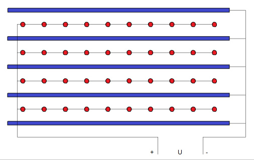
Consider the simplest system of electrodes, which is two parallel metal plates located at a distance L from each other, a potential difference applied to the plates by a voltage U from a high voltage source:
L = 11mm = 1.1cm;
U = 11kV (kilovolt; 1 kilovolt = 1000 volt);

The figure shows the approximate location of the power lines. The density of the lines shows that in most of the space of the interelectrode gap (with the exception of the area near the edges of the plates), the intensity has the same value. Such a uniform electric field is called homogeneous [2, 3, 4]. The value of tension in the space between the plates for this electrode system can be calculated from a simple equation [1, 2.]:
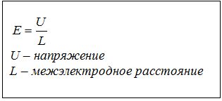
So, at a voltage of 11kV, the voltage will be 10kV / cm. Under these conditions, the atmospheric air that fills the space between the plates is an electrical insulator (dielectric), that is, it does not conduct electrical current, therefore no current will flow in the electrode system. Let's check it in practice.
Two parallel plates, uniform electric field;
L = 11mm = 1.1cm;
U = 11 ... 22kV.
According to the testimony of a microammeter, you can see that there is really no electric current. Nothing has changed at a voltage of 22kV, and even at 25kV (maximum for my high voltage source).
Volt-ampere characteristics:
A strong electric field is able to turn the air gap into an electrical conductor - for this it is necessary that its intensity in the gap exceeds a certain critical (breakdown) value. When this happens, ionization processes begin to flow in the air with high intensity: mainly impact ionization and photoionization , which leads to an avalanche-like increase in the number of free charge carriers — ions and electrons. At some point in time, a conductive channel is formed (filled with charge carriers), covering the interelectrode gap through which current begins to flow (the phenomenon is called electrical breakdown or discharge). In the zone of ionization processes, chemical reactions take place (including the dissociation of molecules that make up the air), which leads to the production of a certain amount of toxic gases (ozone, nitrogen oxides).
Ionization processes [1, 2]
Impact ionization
Free electrons and ions of various signs, always present in atmospheric air in small quantities, under the action of an electric field will rush in the direction of the electrode of opposite polarity (electrons and negative ions - to positive, positive ions - to negative). Some of them will collide with atoms and air molecules along the way. If the kinetic energy of moving electrons / ions is sufficient (and it is higher, the higher the field strength), then during collisions electrons are knocked out of neutral atoms, resulting in the formation of new free electrons and positive ions. In turn, new electrons and ions will also be accelerated by an electric field, and some of them will be able to ionize other atoms and molecules in this way. So the number of ions and electrons in the interelectrode space begins to increase in an avalanche-like manner.
Photoionization
Atoms or molecules that have received an amount of energy insufficient for ionization during a collision emit it in the form of photons (the atom / molecule tends to return to its previous stable energy state). Photons can be absorbed by an atom or molecule, which can also lead to ionization (if the photon energy is enough to detach an electron).
For parallel plates in atmospheric air, the critical value of the electric field strength can be calculated from the equation [1]:
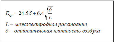
For the considered electrode system, the critical intensity (under normal atmospheric conditions) is about 30.6 kV / cm, and the breakdown voltage is 33.6 kV. Unfortunately, my high voltage source cannot produce more than 25kV, therefore, in order to observe the electrical breakdown of air, I had to reduce the interelectrode distance to 0.7cm (critical intensity 32.1kV / cm; breakdown voltage 22.5kV).
Observation of electrical breakdown of the air gap. We will increase the potential difference applied to the electrodes before electrical breakdown occurs.
L = 7mm = 0.7cm;
U = 14 ... 25kV.
Breakdown of the gap in the form of a spark discharge was observed at a voltage of 21.5 kV. The discharge emitted light and sound (click), the arrows of the current meters were deflected (meaning that the electric current was leaking). At the same time, there was a smell of ozone in the air (the same smell, for example, occurs when UV lamps work during quartz treatment of rooms in hospitals).
Volt-ampere characteristics:
In the electrode system, we replace the positive plate electrode with a thin wire electrode with a diameter of 0.1 mm (ie, R1 = 0.05 mm), also located parallel to the negative plate electrode. In this case, in the space of the interelectrode gap, in the presence of a potential difference, a non-uniform electric field [2, 4] is formed: the closer the point of space is to the wire electrode, the higher the value of the electric field intensity. The figure below presents an approximate picture of the distribution:

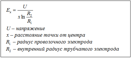
For clarity, you can build a more accurate picture of the distribution of tension - it is easier to do this for an equivalent electrode system, where the plate electrode is replaced with a tubular electrode located coaxial to the corona electrode:
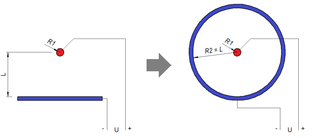
For this electrode system, the intensity values at the points of the interelectrode space can be determined from a simple equation [1, 2]:
The figure below shows the calculated picture for the values:
R1 = 0.05mm = 0.005cm;
R2 = 11mm = 1.1cm;
U = 5kV;
Lines characterize the value of tension at a given distance; the values of neighboring lines differ by 1kV / cm.
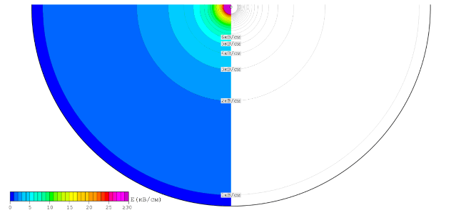
It can be seen from the distribution picture that in most of the interelectrode space the intensity varies slightly, and near the wire electrode, as it approaches it, it increases dramatically.
In the wire-plane electrode system (or similar, in which the radius of curvature of one electrode is substantially less than the interelectrode distance), as we saw from the picture of the distribution of intensity, the existence of an electric field is possible with the following features:
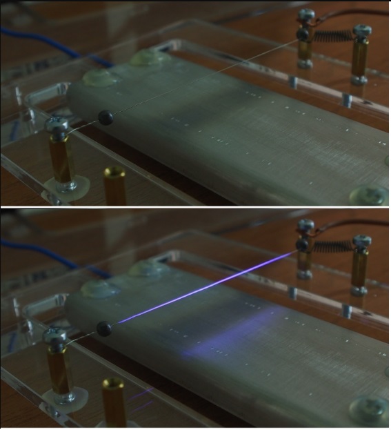
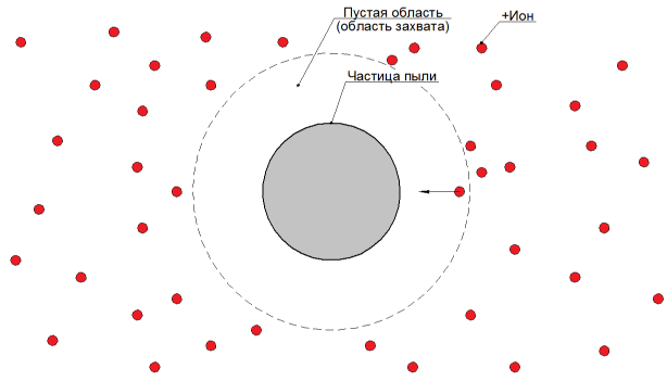
With this configuration of the electric field, an electrical breakdown of air is formed, localized in a small area near the wire and not overlapping the interelectrode gap (see photo). Such an incomplete electrical discharge is called a corona discharge [1, 2], and the electrode near which it is formed is called the corona electrode [2].
In the interelectrode gap with a corona discharge, two zones are distinguished [1]: the ionization zone (or discharge cover) and the drift zone :
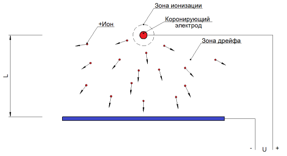
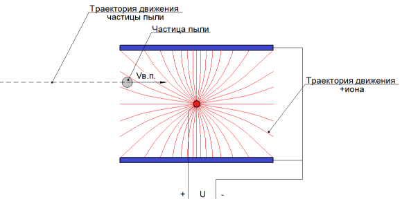
In the ionization zone, as the name suggests, ionization processes take place — impact ionization and photoionization, and ions of different signs and electrons are formed. The electric field present in the interelectrode space affects the electrons and ions, due to which electrons and negative ions (if present) rush to the corona-forming electrode, and positive ions are forced out of the ionization zone and enter the drift zone.
In the drift zone, which accounts for the main part of the interelectrode gap (the whole gap space except for the ionization zone), ionization processes do not proceed. Here the set of positive ions drifting under the action of an electric field (mainly in the direction of the plate electrode) is distributed.
Due to the directional movement of charges (positive ions close the current to the plate electrode, and electrons and negative ions to the corona electrode) electric current flows in the gap, the corona discharge current [2, 3].
In atmospheric air, depending on the conditions, a positive corona discharge can take one of the forms [1]: avalanche or streamer . The avalanche form is observed in the form of a uniform thin luminous layer covering a smooth electrode (for example, a wire), above was a photo. The streamer form is observed in the form of thin luminous filamentary channels (streamers) directed from the electrode and more often occurs on electrodes with sharp irregularities (teeth, spikes, needles), the photo below:

As in the case of a spark discharge, a side effect of the flow of any form of corona discharge in the air (due to the presence of ionization processes) is the production of harmful gases - ozone and nitrogen oxides.
Observation of a positive avalanche corona discharge. Corona electrode - wire, positive power;
L = 11 mm = 1.1cm;
R1 = 0.05 mm = 0.005cm
Glow discharge:
The corona process (electric current appeared) began at U = 6.5 kV, while the surface of the wire electrode began to uniformly become covered with a thin weakly luminous layer and the smell of ozone appeared. Ionization processes are concentrated in this luminous region (corona discharge cover). With increasing voltage, an increase in the glow intensity and a nonlinear increase in current was observed, and when U = 17.1kV was reached, the interelectrode gap overlapped (corona discharge turned into a spark discharge).
Volt-ampere characteristics:
Observation of a negative corona discharge. Swap the wires of the power supply of the electrode system (negative wire to the wire electrode, positive wire to the plate). Corona electrode - wire, negative power;
L = 11 mm;
R1 = 0.05 mm = 0.005 cm.
Glow:
Coronation began at U = 7.5kV. The nature of the negative corona glow was significantly different from that of the positive corona: now, separate pulsating glowing equidistant points from each other appeared on the corona electrode. With an increase in the applied voltage, the discharge current increased, as well as the number of luminous points and the intensity of their glow increased. The smell of ozone was felt stronger than with a positive crown. Spark gap occurred at U = 18.5 kV.
Volt-ampere characteristics:
Observation of positive streamer corona discharge. Replace the wire electrode in the electrode system on the sawtooth electrode and return the polarity of the power supply to its original state. Corona electrode - toothed, positive power;
L = 11 mm = 1.1cm;
Glow:
The corona process began at U = 5.5 kV, while on the tips of the corona electrode there appeared thin luminous channels (streamers) directed toward the plate electrode. As the voltage increased, the size and intensity of the luminescence of these channels, as well as the corona current, increased. The smell of ozone was felt something like a positive avalanche crown. The transition of the corona discharge to the spark discharge occurred at U = 13kV.
- :
, , , , . , , [1,2,3,4]:
, [3,4]. [3,4] ( ).
: ( / / ) V.. , ( ).
(), .
, , , - . [1,2,4] – , . , ( ), – [1,2,4]. , [4].
[1]
, . , , , ( , ).
, . , , ( ), , :
- ( ), .
, ( ), [1,4]. .
, , :
[2,4] ( , ). [1,3,4].
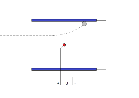
, , - , [1,2,3,4] F, - – W:
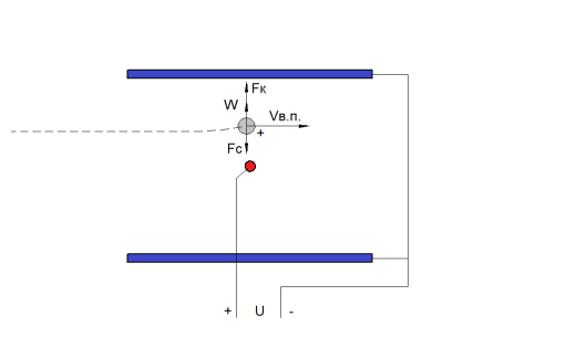
[1,2,4]:
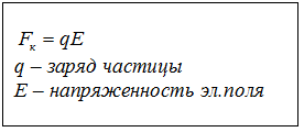
- [1,2] F, , , , . [1]: , – .
- , [4]:
, . .
, :
. [4], , – , / . , , , ( , ).
:
, . , ; - .
: , (), - () :

, , :
, :
, , . , , , ( 0,1 [2,3]) ( ).
( ) , , , , , . , [3] – . , , – . [1,3] 1 / ( 0,5…2,5 /).
S , ( ) , , :
, (- ):

[4] ( ) .
(L → *L) (*A < A), , :
- U, - . , , ( , ). , . :

[4] ( ) . , .
, , :
, . , , , . . - . , , .
, . :
.
:

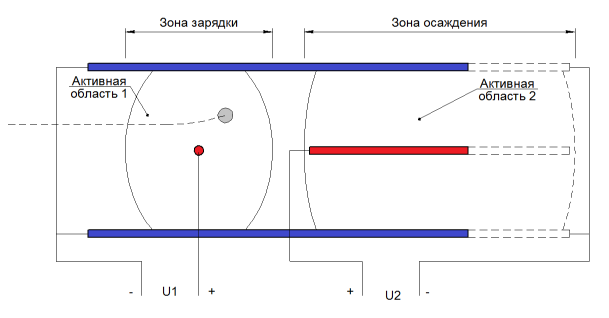
– 2 : ( 1), , ( 2), . , : () (), — [2,3]. [1,2] , U2, ( 2). : L=30: ; 10/ [1]; 28/, (, 2 ).
, , , . , . , , ( ) . :
( 2), , . ( , ).
: :

, :
, L=30 28/, L=6 – 32/, 14% .
2 , , . .
Ultimately, we came to a two-zone electrode system with high quality of purification from suspended particles, even small ones, the trapping of which causes the greatest difficulties (low ability to charge and, consequently, low drift velocity) with a low level of produced toxic gases (provided use of positive avalanche crown). The design has drawbacks: with a high quantitative concentration of dust, the phenomenon of corona locking will occur, which can lead to a significant decrease in the cleaning efficiency. As a rule, the air of residential premises does not contain such a large amount of pollution, therefore such a problem should not arise. Due to a good combination of characteristics, devices with similar electrode systems are successfully used for fine air purification in rooms.
If possible, in the next part, materials on the construction and assembly of the full-area two-zone electrostatic air purifier will be laid out at home.
Many thanks to Yana Zhirovaya for providing the camera: without it, the quality of photo and video materials would be much worse, and the photo of the corona discharge would be completely absent.
Nazarov Mikhail.
In the first part I suggest to get acquainted with the principles of operation of these devices, and in the next - to build a full-fledged cleaner with your own hands.
In the photo, corona discharge used in electrostatic air purifiers
Content
Sources of dust and affordable household air purifiers
Uniform electric field and electrical air breakdown
Inhomogeneous electric field and corona discharge in air
Principle of electrical air cleaning
Electrode Electrostatic Filter Systems
Conclusion
Sources
')
Why do you need a cleaner
Airborne fine dust particles PM10 and PM2.5 are able to penetrate into our body when breathing: bronchi, lungs, and even enter the bloodstream. According to the World Health Organization (WHO) , air pollution with such particles poses a serious health hazard: exposure to air with a high content of such particles (PM2.5 exceeding the average annual concentration of 10 µg / cubic meter and daily average 25 µg / cubic meter; exceeding the PM10 average annual 20 μg / m 3 and average daily 50 μg / m 3) increases the risk of respiratory diseases, diseases of the cardiovascular system and some oncological diseases, pollution has already been assigned to Group 1 of carcinogens . Highly toxic particles (containing lead, cadmium, arsenic, beryllium, tellurium, etc., as well as radioactive compounds) are dangerous even at low concentrations.
The easiest step to reducing the negative effects of dust on the body is to install an effective air purifier in a sleeping room, where a person spends about a third of the time.
Dust sources
Major natural suppliers of dust are volcanic eruptions, the ocean (evaporation of splashes), natural fires, soil erosion (for example, dust storms: Zabol , Iraq), earthquakes and various earth falls, plant pollen, spores of fungi, biomass decomposition processes, etc.
The anthropogenic sources include the processes of burning of minerals (energy and industry), transportation of fragile / bulk materials and loading operations (see Vostochny port, Nakhodka, Vanino port, Khabarovsk territory), crushing of materials (mining, building materials, agricultural industry), mechanical processing, chemical processes, thermal operations (welding, melting), operation of vehicles (exhaust of internal combustion engines, tire and pavement wear).
The presence of dust particles in the premises due to the flow of polluted outside air, as well as the presence of internal sources: the destruction of materials (clothes, linen, carpets, furniture, building materials, books), cooking, human activity (parts of the epidermis, hair), moldy mushrooms, mites home dust , etc.
Available air purifiers
To reduce the concentration of dust particles (including the most dangerous - less than 10 microns in size) household appliances are available that work on the following principles:
- mechanical filtration;
- air ionization;
- electrostatic precipitation (electrostatic precipitators).
The method of mechanical filtration is the most common. The principles of particle trapping by these filters have already been described here . To capture fine solid particles, high-performance (more than 85%) fibrous filter elements are used (EPA, HEPA standards). Such devices do a good job, but they have some drawbacks:
- high hydraulic resistance of the filter element;
- the need for frequent replacement of expensive filter element.
Due to the high resistance, the developers of such cleaners are forced to provide a large area of the filter element, use powerful, but low-noise fans, get rid of the cracks in the device case (since even a small air leakage bypassing the filter element significantly reduces the cleaning efficiency of the device).
When working, the air ionizer electrically charges dust particles suspended in the air of the room, due to which the latter are deposited on the floor, walls, ceiling or objects in the room. Particles remain in the room and can return to a suspended state, so the solution does not look satisfactory. In addition, the device significantly changes the ionic composition of air, and the effect of such air on people is currently not well understood.
The operation of the electrostatic cleaner is based on the same principle: the particles entering the device are first electrically charged, then attracted by electric forces to special plates charged with an opposite charge (all this happens inside the device). When a layer of dust accumulates on the plates, cleaning is performed. These cleaners have high efficiency (more than 80%) of trapping particles of different sizes, low hydraulic resistance, and do not require periodic replacement of consumable items. There are also disadvantages: the production of a certain amount of toxic gases (ozone, nitrogen oxides), complex construction (electrode assemblies, high voltage power supply), the need for periodic cleaning of the collecting plates.
Air Purifier Requirements
When using a recirculating air purifier (such a cleaner sucks in air from the room, filters and then returns to the room), the characteristics of the device (one-pass efficiency, volumetric capacity) and the volume of the target room must be taken into account, otherwise the device may be useless. For this purpose, the American organization AHAM has developed a CADR indicator that takes into account the one-pass cleaning efficiency and the volumetric capacity of the cleaner, as well as a method for calculating the required CADR for a given room. There is already a good description of this indicator. AHAM recommends using a cleaner with a CADR value greater than or equal to five times the volume of the room per hour. For example, for a room with an area of 20 square meters and a ceiling height of 2.5 m, the CADR indicator should be 20 * 2.5 * 5 = 250 cubic meters / hour (or 147CFM) or more.
Also, the cleaner during operation should not create any harmful factors: exceeding the permissible values of the noise level, exceeding the permissible concentrations of harmful gases (in the case of using an electrostatic precipitator).
Homogeneous electric field
From the physics course, we remember that an electric field is formed near a body with an electric charge [2].
The strength characteristic of the field is the intensity E [Volt / m or kV / cm]. The electric field strength is a vector quantity (it has a direction). Graphically depict the strength taken by the force lines (the tangents to the points of the force curves coincide with the direction of the intensity vector at these points), the intensity value is characterized by the density of these lines (the more densely the lines are located - the greater the intensity takes in this area).
Consider the simplest system of electrodes, which is two parallel metal plates located at a distance L from each other, a potential difference applied to the plates by a voltage U from a high voltage source:
L = 11mm = 1.1cm;
U = 11kV (kilovolt; 1 kilovolt = 1000 volt);
The figure shows the approximate location of the power lines. The density of the lines shows that in most of the space of the interelectrode gap (with the exception of the area near the edges of the plates), the intensity has the same value. Such a uniform electric field is called homogeneous [2, 3, 4]. The value of tension in the space between the plates for this electrode system can be calculated from a simple equation [1, 2.]:
So, at a voltage of 11kV, the voltage will be 10kV / cm. Under these conditions, the atmospheric air that fills the space between the plates is an electrical insulator (dielectric), that is, it does not conduct electrical current, therefore no current will flow in the electrode system. Let's check it in practice.
Actually the air conducts very little
In atmospheric air, there is always [1] a small amount of free charge carriers — electrons and ions, which are formed as a result of exposure to natural external factors — for example, radiation background and UV radiation. The concentration of these charges is very low, so the current density is very small, my equipment is unable to register such values.
Equipment for experiments
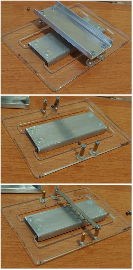
For carrying out small practical experiments, a high voltage source (IVN), a test electrode system and a “test bench” will be used.
The electrode system can be assembled into one of three options: "two parallel plates", "wire-plate" or "teeth-plate":
The interelectrode distance for all options is the same and is 11 mm.
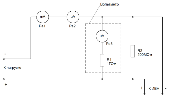
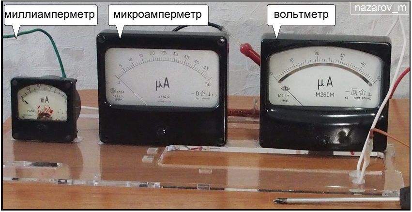
The bench consists of measuring devices:
electrical circuit:
At high voltages, some non-conductive materials suddenly begin to conduct electricity (for example, furniture), so everything is mounted on a sheet of plexiglass. This mess looks like this:
Of course, the accuracy of measurements with such equipment leaves much to be desired, but it should be enough to observe the general laws (better than nothing!). With the entries we finish, get down to business.
The electrode system can be assembled into one of three options: "two parallel plates", "wire-plate" or "teeth-plate":
The interelectrode distance for all options is the same and is 11 mm.
The bench consists of measuring devices:
- 50kV voltmeter (Pa3 microammeter at 50 μA with an additional resistance of R1 1 GΩ; 1 μA of readings corresponds to 1 kV);
- Pa2 microammeter on 50µA;
- milliammeter Pa1 at 1mA.
electrical circuit:
At high voltages, some non-conductive materials suddenly begin to conduct electricity (for example, furniture), so everything is mounted on a sheet of plexiglass. This mess looks like this:
Of course, the accuracy of measurements with such equipment leaves much to be desired, but it should be enough to observe the general laws (better than nothing!). With the entries we finish, get down to business.
Experiment # 1
Two parallel plates, uniform electric field;
L = 11mm = 1.1cm;
U = 11 ... 22kV.
According to the testimony of a microammeter, you can see that there is really no electric current. Nothing has changed at a voltage of 22kV, and even at 25kV (maximum for my high voltage source).
Volt-ampere characteristics:
| U, kV | E, kV / cm | I, mkA |
|---|---|---|
| 0 | 0 | 0 |
| eleven | ten | 0 |
| 22 | 20 | 0 |
| 25 | 22.72 | 0 |
Electrical breakdown of air gap
A strong electric field is able to turn the air gap into an electrical conductor - for this it is necessary that its intensity in the gap exceeds a certain critical (breakdown) value. When this happens, ionization processes begin to flow in the air with high intensity: mainly impact ionization and photoionization , which leads to an avalanche-like increase in the number of free charge carriers — ions and electrons. At some point in time, a conductive channel is formed (filled with charge carriers), covering the interelectrode gap through which current begins to flow (the phenomenon is called electrical breakdown or discharge). In the zone of ionization processes, chemical reactions take place (including the dissociation of molecules that make up the air), which leads to the production of a certain amount of toxic gases (ozone, nitrogen oxides).
Ionization processes [1, 2]
Impact ionization
Free electrons and ions of various signs, always present in atmospheric air in small quantities, under the action of an electric field will rush in the direction of the electrode of opposite polarity (electrons and negative ions - to positive, positive ions - to negative). Some of them will collide with atoms and air molecules along the way. If the kinetic energy of moving electrons / ions is sufficient (and it is higher, the higher the field strength), then during collisions electrons are knocked out of neutral atoms, resulting in the formation of new free electrons and positive ions. In turn, new electrons and ions will also be accelerated by an electric field, and some of them will be able to ionize other atoms and molecules in this way. So the number of ions and electrons in the interelectrode space begins to increase in an avalanche-like manner.
Photoionization
Atoms or molecules that have received an amount of energy insufficient for ionization during a collision emit it in the form of photons (the atom / molecule tends to return to its previous stable energy state). Photons can be absorbed by an atom or molecule, which can also lead to ionization (if the photon energy is enough to detach an electron).
For parallel plates in atmospheric air, the critical value of the electric field strength can be calculated from the equation [1]:
For the considered electrode system, the critical intensity (under normal atmospheric conditions) is about 30.6 kV / cm, and the breakdown voltage is 33.6 kV. Unfortunately, my high voltage source cannot produce more than 25kV, therefore, in order to observe the electrical breakdown of air, I had to reduce the interelectrode distance to 0.7cm (critical intensity 32.1kV / cm; breakdown voltage 22.5kV).
Experiment # 2
Observation of electrical breakdown of the air gap. We will increase the potential difference applied to the electrodes before electrical breakdown occurs.
L = 7mm = 0.7cm;
U = 14 ... 25kV.
Breakdown of the gap in the form of a spark discharge was observed at a voltage of 21.5 kV. The discharge emitted light and sound (click), the arrows of the current meters were deflected (meaning that the electric current was leaking). At the same time, there was a smell of ozone in the air (the same smell, for example, occurs when UV lamps work during quartz treatment of rooms in hospitals).
Volt-ampere characteristics:
| U, kV | E, kV / cm | I, mkA |
|---|---|---|
| 0 | 0 | 0 |
| 14 | 20 | 0 |
| 21 | thirty | 0 |
| 21.5 | 30.71 | breakdown |
Non-uniform electric field
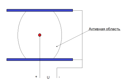
In the electrode system, we replace the positive plate electrode with a thin wire electrode with a diameter of 0.1 mm (ie, R1 = 0.05 mm), also located parallel to the negative plate electrode. In this case, in the space of the interelectrode gap, in the presence of a potential difference, a non-uniform electric field [2, 4] is formed: the closer the point of space is to the wire electrode, the higher the value of the electric field intensity. The figure below presents an approximate picture of the distribution:
For clarity, you can build a more accurate picture of the distribution of tension - it is easier to do this for an equivalent electrode system, where the plate electrode is replaced with a tubular electrode located coaxial to the corona electrode:
For this electrode system, the intensity values at the points of the interelectrode space can be determined from a simple equation [1, 2]:
The figure below shows the calculated picture for the values:
R1 = 0.05mm = 0.005cm;
R2 = 11mm = 1.1cm;
U = 5kV;
Lines characterize the value of tension at a given distance; the values of neighboring lines differ by 1kV / cm.
It can be seen from the distribution picture that in most of the interelectrode space the intensity varies slightly, and near the wire electrode, as it approaches it, it increases dramatically.
Corona discharge
In the wire-plane electrode system (or similar, in which the radius of curvature of one electrode is substantially less than the interelectrode distance), as we saw from the picture of the distribution of intensity, the existence of an electric field is possible with the following features:
- in a small area close to the wire electrode, the electric field strength can reach high values (well above 30kV / cm), sufficient for the occurrence of intense ionization processes in the air;
- at the same time, in most of the interelectrode space, the electric field strength will take on low values - less than 10 kV / cm.
With this configuration of the electric field, an electrical breakdown of air is formed, localized in a small area near the wire and not overlapping the interelectrode gap (see photo). Such an incomplete electrical discharge is called a corona discharge [1, 2], and the electrode near which it is formed is called the corona electrode [2].
In the interelectrode gap with a corona discharge, two zones are distinguished [1]: the ionization zone (or discharge cover) and the drift zone :
In the ionization zone, as the name suggests, ionization processes take place — impact ionization and photoionization, and ions of different signs and electrons are formed. The electric field present in the interelectrode space affects the electrons and ions, due to which electrons and negative ions (if present) rush to the corona-forming electrode, and positive ions are forced out of the ionization zone and enter the drift zone.
In the drift zone, which accounts for the main part of the interelectrode gap (the whole gap space except for the ionization zone), ionization processes do not proceed. Here the set of positive ions drifting under the action of an electric field (mainly in the direction of the plate electrode) is distributed.
Due to the directional movement of charges (positive ions close the current to the plate electrode, and electrons and negative ions to the corona electrode) electric current flows in the gap, the corona discharge current [2, 3].
In atmospheric air, depending on the conditions, a positive corona discharge can take one of the forms [1]: avalanche or streamer . The avalanche form is observed in the form of a uniform thin luminous layer covering a smooth electrode (for example, a wire), above was a photo. The streamer form is observed in the form of thin luminous filamentary channels (streamers) directed from the electrode and more often occurs on electrodes with sharp irregularities (teeth, spikes, needles), the photo below:
As in the case of a spark discharge, a side effect of the flow of any form of corona discharge in the air (due to the presence of ionization processes) is the production of harmful gases - ozone and nitrogen oxides.
Experiment # 3
Observation of a positive avalanche corona discharge. Corona electrode - wire, positive power;
L = 11 mm = 1.1cm;
R1 = 0.05 mm = 0.005cm
Glow discharge:
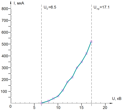
The corona process (electric current appeared) began at U = 6.5 kV, while the surface of the wire electrode began to uniformly become covered with a thin weakly luminous layer and the smell of ozone appeared. Ionization processes are concentrated in this luminous region (corona discharge cover). With increasing voltage, an increase in the glow intensity and a nonlinear increase in current was observed, and when U = 17.1kV was reached, the interelectrode gap overlapped (corona discharge turned into a spark discharge).
Volt-ampere characteristics:
| U, kV | I, mkA |
|---|---|
| 0 | 0 |
| 6.5 | one |
| 7 | 2 |
| eight | 20 |
| 9 | 40 |
| ten | 60 |
| eleven | 110 |
| 12 | 180 |
| 13 | 220 |
| 14 | 300 |
| 15 | 350 |
| sixteen | 420 |
| 17 | 520 |
| 17.1 | overlap |
Experiment # 4
Observation of a negative corona discharge. Swap the wires of the power supply of the electrode system (negative wire to the wire electrode, positive wire to the plate). Corona electrode - wire, negative power;
L = 11 mm;
R1 = 0.05 mm = 0.005 cm.
Glow:
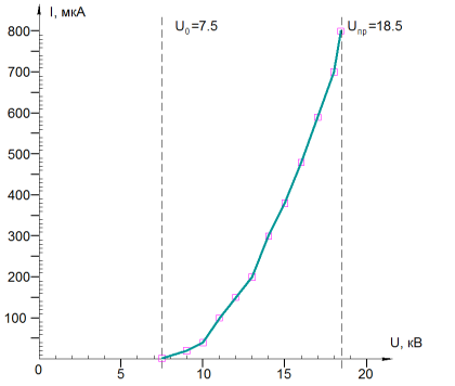
Coronation began at U = 7.5kV. The nature of the negative corona glow was significantly different from that of the positive corona: now, separate pulsating glowing equidistant points from each other appeared on the corona electrode. With an increase in the applied voltage, the discharge current increased, as well as the number of luminous points and the intensity of their glow increased. The smell of ozone was felt stronger than with a positive crown. Spark gap occurred at U = 18.5 kV.
Volt-ampere characteristics:
| U, kV | I, mkA |
|---|---|
| 0 | 0 |
| 7.5 | one |
| eight | four |
| 9 | 20 |
| ten | 40 |
| eleven | 100 |
| 12 | 150 |
| 13 | 200 |
| 14 | 300 |
| 15 | 380 |
| sixteen | 480 |
| 17 | 590 |
| 18 | 700 |
| 18.4 | 800 |
| 18.5 | overlap |
Experiment # 5
Observation of positive streamer corona discharge. Replace the wire electrode in the electrode system on the sawtooth electrode and return the polarity of the power supply to its original state. Corona electrode - toothed, positive power;
L = 11 mm = 1.1cm;
Glow:
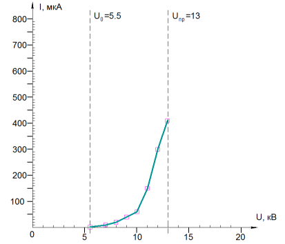
The corona process began at U = 5.5 kV, while on the tips of the corona electrode there appeared thin luminous channels (streamers) directed toward the plate electrode. As the voltage increased, the size and intensity of the luminescence of these channels, as well as the corona current, increased. The smell of ozone was felt something like a positive avalanche crown. The transition of the corona discharge to the spark discharge occurred at U = 13kV.
- :
| U, | I, |
|---|---|
| 0 | 0 |
| 5.5 | one |
| 6 | 3 |
| 7 | ten |
| eight | 20 |
| 9 | 35 |
| ten | 60 |
| eleven | 150 |
| 12 | 300 |
| 12.9 | 410 |
| 13 |
, , , , . , , [1,2,3,4]:
- :
- ;
- ;
- , ;
- , :
- ;
- humidity;
- temperature;
- ;
- ( , : , , )
- ( ) , .
, [3,4]. [3,4] ( ).
:
: ( / / ) V.. , ( ).
(), .
, , , - . [1,2,4] – , . , ( ), – [1,2,4]. , [4].
[1]
, . , , , ( , ).
, . , , ( ), , :
- ( ), .
, ( ), [1,4]. .
, , :
- ( , );
- , ;
- , [1,4] ( , )
[2,4] ( , ). [1,3,4].
, , - , [1,2,3,4] F, - – W:
[1,2,4]:
- [1,2] F, , , , . [1]: , – .
- , [4]:
- , ;
- ;
- , ( ).
, . .
, :
- ;
- ( ) ( ).
. [4], , – , / . , , , ( , ).
:
- ; [2,3] ( ), , ( ), [1]; ;
- :
- , , ( ), :
- [2,3] (- ), ;
- [2], , ;
- , , ( ), :
- [1,2] ( ) , .
, . , ; - .
: , (), - () :
, , :
- ;
- , , .
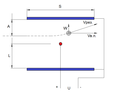
, :
- W;
- V..;
- S ;
- L, A ( , ).
, , . , , , ( 0,1 [2,3]) ( ).
( ) , , , , , . , [3] – . , , – . [1,3] 1 / ( 0,5…2,5 /).
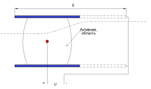
S , ( ) , , :
, (- ):
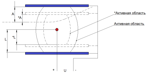
[4] ( ) .
(L → *L) (*A < A), , :
- U, - . , , ( , ). , . :
[4] ( ) . , .
, , :
, . , , , . . - . , , .
, . :
- ( ), ;
- , , .
.
:
– 2 : ( 1), , ( 2), . , : () (), — [2,3]. [1,2] , U2, ( 2). : L=30: ; 10/ [1]; 28/, (, 2 ).
, , , . , . , , ( ) . :
( 2), , . ( , ).
: :
, :
- , , ;
- ( ), .
, L=30 28/, L=6 – 32/, 14% .
2 , , . .
Conclusion
Ultimately, we came to a two-zone electrode system with high quality of purification from suspended particles, even small ones, the trapping of which causes the greatest difficulties (low ability to charge and, consequently, low drift velocity) with a low level of produced toxic gases (provided use of positive avalanche crown). The design has drawbacks: with a high quantitative concentration of dust, the phenomenon of corona locking will occur, which can lead to a significant decrease in the cleaning efficiency. As a rule, the air of residential premises does not contain such a large amount of pollution, therefore such a problem should not arise. Due to a good combination of characteristics, devices with similar electrode systems are successfully used for fine air purification in rooms.
If possible, in the next part, materials on the construction and assembly of the full-area two-zone electrostatic air purifier will be laid out at home.
Many thanks to Yana Zhirovaya for providing the camera: without it, the quality of photo and video materials would be much worse, and the photo of the corona discharge would be completely absent.
Nazarov Mikhail.
Sources
- Electrophysical bases of high voltage technology. I.P. Vereshchagin, Yu.N. Vereshchagin. - M .: Energoatomizdat, 1993;
- Purification of industrial gases with electrostatic precipitators. V.N. Uzhov. - M .: Publishing House "Chemistry", 1967;
- Technique dust removal and purification of industrial gases. G.M.-A. Aliyev. - M .: Metallurgy, 1986;
- Industrial gas cleaning: Trans. from English - M., Chemistry, 1981.
Source: https://habr.com/ru/post/371071/
All Articles