Processor Design (CPU Design) Proteus
Part I
Part II
We will create a device that allows the operation "subtraction". In order to subtract a number, you must first translate it into a reverse code (replace all 0 with 1; all 1 with 0), and then into an additional code (add 1).
For storing numbers we will use 155ru2 (RAM), for translation into the reverse code we will use 155ln2 (six Elements Not). These microcircuits have open collector outputs. The LED to the output with OK should be connected as follows (for example, 155ln2 / 7405)

For MS 155ru2, we assume that the synchronization input and the recording resolution input are combined into one line. This (combined) input is static, the MS skips through all the time, while at the input there is 0 (low level).
')
Data enters the MS when a low level appears at this (combined) input, therefore we will hang the Element not to the clock input.
The outputs will be inverted, if connected according to the scheme I gave above for the output with OK (hang Elements Not to outputs), the chip select input is also inverted, the MS performs a write or read cycle only at the zero level on this input (hang Element Not to the input crystal selection).
Also, the MS has separate inputs for the address and for the data, so when choosing a standard RAM module (Side menu - Memory - RAM) on the “Data Interface” tab, you must select “Separate read and write ports”.
So The model closest to 155ru2 will be:

http://www.microshemca.ru/RU2/
To select a number in the direct or inverse code, we will use a multiplexer. We will store the numbers 8, 4 (in the reverse code), 1

"Physical" model.

Let us combine our scheme with the previous one and subtract 4 from 8, i.e. 8 + 4 (in the return code) + 1

So we have created the simplest programmable device in which teams select the number in the direct or reverse code.
##### ##### #####
We will design a scheme that allows storing numbers in memory, adding numbers (stored in memory), and also making unconditional transitions in the Proteus ISIS simulator.
Demo-version of the program can be downloaded from the official site .

We will need, in fact, RAM (6116) memory, a counter for searching data in memory (74HC160), a multiplexer (74HC153), an adder (74HC283), a battery (74HC77), a controlled buffer (74HC244).

This scheme can be downloaded from here .
Let's design allowing to put sets of numbers on FPGA / FPGA. We will use Quartus II. The free version with limited functionality can be downloaded from the official site .
When registering in the My Primary Job Function is * section, select Student.
Next, you need to download the driver for the programmer (the driver for usb-blaster can be installed from C: \ altera \ ... \ quartus \ drivers \ usb-blaster).
In the Quartus environment, we will create a new project (“File” / “New” / “New Quartus II Project”) and add a Block Diagram / Schematic File (“File” / “New” / “Block Diagram / Schematic File”) to the project.
We will need an adder (7483) and a battery (74175).
These chips can be added from the Symbol Tool:

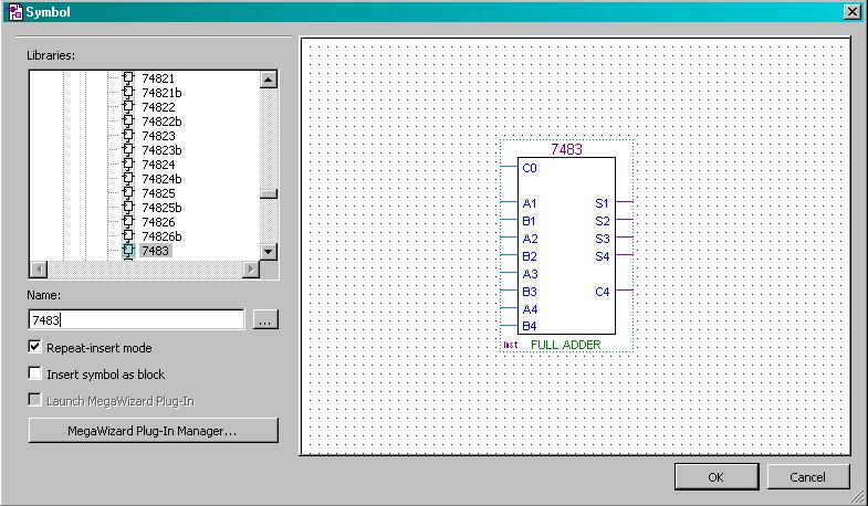
Adding I / O ports ("Symbol Tool" / "primitives" / "pin"), we get a scheme that allows you to add a set of four-digit numbers.

If you use an external clock source, the clock foot of the source must be pulled to the “ground”.
Part II
We will create a device that allows the operation "subtraction". In order to subtract a number, you must first translate it into a reverse code (replace all 0 with 1; all 1 with 0), and then into an additional code (add 1).
For storing numbers we will use 155ru2 (RAM), for translation into the reverse code we will use 155ln2 (six Elements Not). These microcircuits have open collector outputs. The LED to the output with OK should be connected as follows (for example, 155ln2 / 7405)
For MS 155ru2, we assume that the synchronization input and the recording resolution input are combined into one line. This (combined) input is static, the MS skips through all the time, while at the input there is 0 (low level).
')
Data enters the MS when a low level appears at this (combined) input, therefore we will hang the Element not to the clock input.
The outputs will be inverted, if connected according to the scheme I gave above for the output with OK (hang Elements Not to outputs), the chip select input is also inverted, the MS performs a write or read cycle only at the zero level on this input (hang Element Not to the input crystal selection).
Also, the MS has separate inputs for the address and for the data, so when choosing a standard RAM module (Side menu - Memory - RAM) on the “Data Interface” tab, you must select “Separate read and write ports”.
So The model closest to 155ru2 will be:
If the recording mode is selected, the inputs and outputs have complementary codes. To read data from RAM, after fixing the address data, a high level voltage is applied to the WE input, and a low-level CS input input (the conventional name: the chip select input) is applied to the input memory chip. To record signals K155RU2 (7489) is required to set the low-level voltage at the control inputs WE and CS. The address code must also be fixed at this time.
http://www.microshemca.ru/RU2/
To select a number in the direct or inverse code, we will use a multiplexer. We will store the numbers 8, 4 (in the reverse code), 1
"Physical" model.
Let us combine our scheme with the previous one and subtract 4 from 8, i.e. 8 + 4 (in the return code) + 1
So we have created the simplest programmable device in which teams select the number in the direct or reverse code.
##### ##### #####
We will design a scheme that allows storing numbers in memory, adding numbers (stored in memory), and also making unconditional transitions in the Proteus ISIS simulator.
Demo-version of the program can be downloaded from the official site .
We will need, in fact, RAM (6116) memory, a counter for searching data in memory (74HC160), a multiplexer (74HC153), an adder (74HC283), a battery (74HC77), a controlled buffer (74HC244).
This scheme can be downloaded from here .
Let's design allowing to put sets of numbers on FPGA / FPGA. We will use Quartus II. The free version with limited functionality can be downloaded from the official site .
When registering in the My Primary Job Function is * section, select Student.
Next, you need to download the driver for the programmer (the driver for usb-blaster can be installed from C: \ altera \ ... \ quartus \ drivers \ usb-blaster).
In the Quartus environment, we will create a new project (“File” / “New” / “New Quartus II Project”) and add a Block Diagram / Schematic File (“File” / “New” / “Block Diagram / Schematic File”) to the project.
We will need an adder (7483) and a battery (74175).
These chips can be added from the Symbol Tool:
Adding I / O ports ("Symbol Tool" / "primitives" / "pin"), we get a scheme that allows you to add a set of four-digit numbers.
If you use an external clock source, the clock foot of the source must be pulled to the “ground”.
Source: https://habr.com/ru/post/370805/
All Articles