50 shades of stub *. Microcontrollers in switching power supplies
DEC * - Peripheral Independent of the Core in Microchip microcontrollers, also known as CIP - Core Independent Peripheral.
Microcontrollers in switching power supplies
Part 1
Looking ahead, I would like to note that the purpose of this article is not to discuss the advantages or disadvantages of control methods, as well as recommendations for choosing optimal topologies for building Pulsed Power Sources (IIPS) and calculating circuit elements - there are tons of specialized literature for this.
The purpose of the article is to show the fundamental possibility of implementing most topologies of SMPS on the universal periphery of Microchip microcontrollers, to demonstrate the advantages of microcontroller solutions in flexibility and versatility regarding specialized “analog” PWM controllers and ASIC for SMPS.
Below, we will consider solutions based on microcontrollers, but such solutions cannot be called “digital” sources, since the feedback loop is still closed via analog blocks and the PWM signal parameters are generated by the hardware feedback loop, and are not calculated by the processor core. For fully digital solutions, Microchip produces specialized 16-bit digital signal controllers (of the dsPIC33 GS-series series) [1].
What is the IIP made of?
The heart of a switching power supply is a PWM controller. The block diagram of one of the variants of the specialized PWM controller is shown in Figure 1.
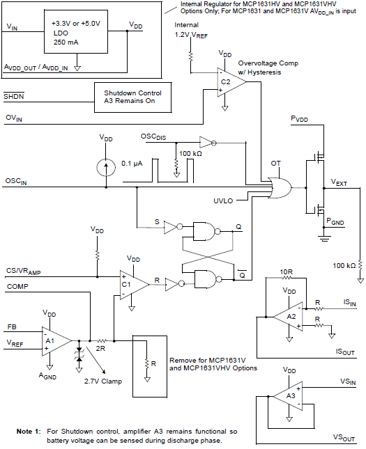
Fig.1. The structure of a specialized power supply driver chip.
The main element of the circuit is the SR flip-flop, which controls the output stage of switching on the power switch.
The trigger is triggered by clock signals (input S, Set). The reset (input R, Reset) is controlled by the signals of the comparator C1, the reference signal for which is generated by the operational amplifier of the error signal A1. The trigger output controls the output keys, the control of which can be blocked by overvoltage signals (comparator C2), blanking, etc.
If it is necessary to control this or similar circuit from the outside (changing and measuring parameters, soft start, etc.), external control solutions, such as a microcontroller or control logic, must be used.
So, to build a managed intelligent power source, we need to have a PWM controller chip and a microcontroller, or we can combine it — on the basis of a microcontroller, to make a PWM controller for an energy converter.
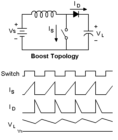
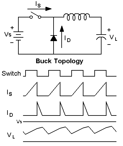
SPS Topologies
Topology is the connection of inductance, capacitor, switching circuit elements to ensure energy conversion, the ratio of input and output parameters.
| scheme | description |
|---|---|
 | boosting |
 | downward |
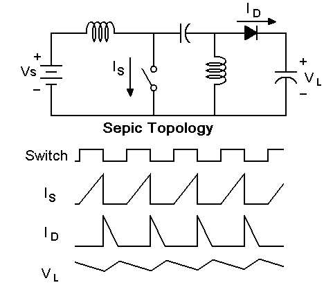 | Sepic |
Fig. 2 Basic topologies of SMPS.
The principle of control of the power key in the most commonly used topologies of the SMPS is in general the same (see Figure 2). The duty ratio of the opening of the power switch the relationship between the "open" and "closed" states. The duty cycle is controlled either depending on the output voltage (voltage control, voltage-mode control), or depending on the current in the power inductance (current control, current-mode control).
In each of the two modes, control can be hysteresis (Hysteretic Control) or proportional (Proportional Control). In hysteresis control, the pulse duty cycle is fixed, and the output voltage is adjusted by turning on or off the supply of control pulses of the power switch.
With proportional control, the duty cycle varies in proportion to the magnitude of the mismatch between the actual output voltage and the required one.
For the widespread topologies of SMPs, industry produces specialized PWM controllers. But what to do if there is no ready PWM controller for the desired topology? In this case, a microcontroller with configurable peripherals can also come to the rescue.
Microcontrollers with PNY
Consider the composition of the periphery of Microchip 8-bit microcontrollers designed for building energy converters.
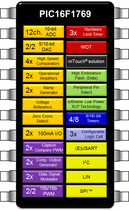
Fig. 3. Peripherals of PIC16F1769 Series Controllers
The PIC16F176x series controllers (see Fig.3) have a set of peripheral modules sufficient for implementing multi-channel PWM controllers of a switching power supply:
- fast comparators;
- operational amplifiers;
- complementary signal generator (COG);
- programmable sawtooth driver (PRG);
- voltage reference;
- DAC;
- ADC;
- zero crossing detector (ZCD);
- timers with reset and limit function, PWM;
- signal modulator;
- Configurable Logic Cells (CLC);
- temperature sensor.
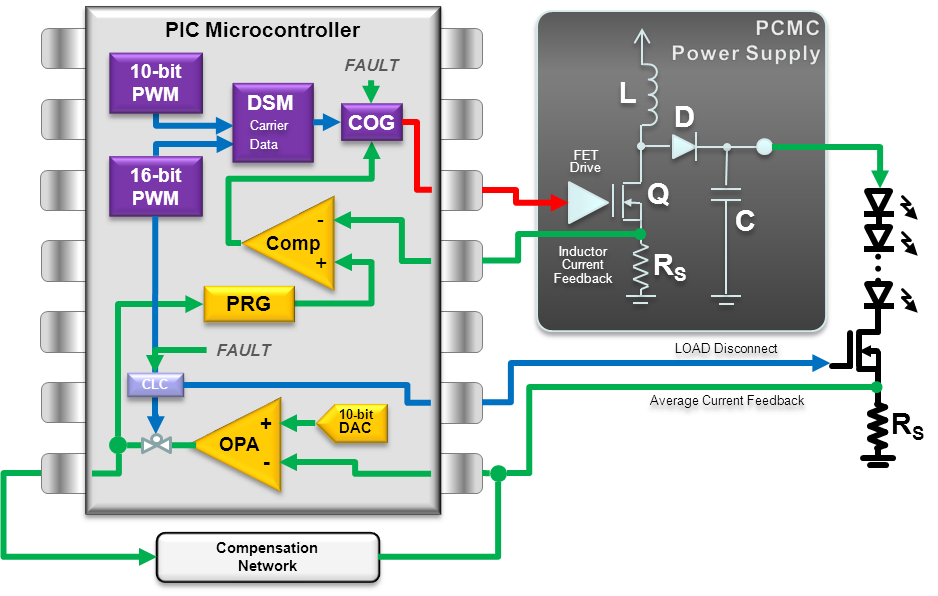
Peripheral modules can be connected inside the microcontroller to perform certain functions. For example, Figure 4 illustrates the configuration of the periphery to perform the function of an energy converter. Moreover, such configured interconnections of peripheral modules do not require the intervention of the kernel during the operation of the device.
Fig. 4. Boost LED power converter with current stabilization and dimming.
Thus, on one chip / microcontroller we can implement the core of the switching power supply and the control logic (program), thus we can eliminate the specialized driver of the power converter from the circuit.
Let us consider in more detail the different modes of operation of PWM controllers and the possibility of their implementation on the periphery of Microchip microcontrollers.
Voltage Control (Voltage Mode)
In this mode, the duty cycle of the PWM signal that controls the power switches is determined directly by the output voltage.
With hysteresis control, if the voltage at the output is below the norm, the source is “pumped”. If the output voltage is greater than the threshold, the comparator blocks the control of the power switch, and the output storage capacity is discharged. In English-language literature, this mode is called “hiccup-mode” - “mode with hiccups”.
This mode is used relatively rarely, as it is accompanied by large ripple output voltage and requires a storage capacitor of relatively high capacity.
Figure 5 demonstrates the principle of operation of the hysteresis controlled voltage mode. Hereinafter, the output part of the source is not shown, since it is determined by the topology, output power, etc. To illustrate how the PWM controller works, an example with the output part will sometimes be shown.

Fig. 5a. The first scheme - with a fixed output voltage, the second - with adjustable output voltage.
Fig. 5 B. Diagrams of PWM output and comparator output.
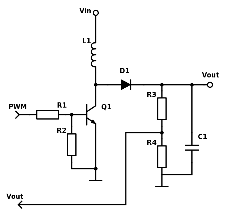
Fig. 6. An example of an output stage of a step-up switching power supply connected to a PWM controller (see figure 5).
Configurable logical cells (CLC) in Fig. 5 can be enabled as an element I. To prevent high-frequency generation from the comparator, it is advisable to pass its output through another CLC, the D-trigger with synchronization from the PWM signal. In this case, we get two “bonuses” - the absence of high-frequency generation and the constant duty cycle of the PWM controller (see the explanations in Fig. 7). For more information about configurable logic cells, see the article "Configurable logic cells in PIC microcontrollers" [2].
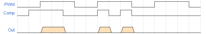
Fig.7.a. Shortening control PWM pulses, the possibility of high-frequency generation
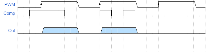
Fig. 7.b. Synchronization of signals helps to prevent the shortening of PWM pulses
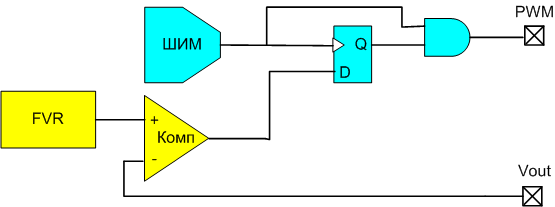
Fig. 8. Synchronization of signals to prevent the generation and shortening of PWM.
Voltage control with proportional control
For voltage control with proportional control, the output voltage mismatch should correct for the duty cycle of the control pulses. The proportion between the magnitude of the mismatch and the magnitude of the correction of the duty ratio provides an error amplifier and filter control loop. The proportional control voltage control is used relatively rarely, since with this control method the inductance may saturate when the source is started and during a short circuit at the output, a second-order loop filter is required and there is an effect of the input voltage on the gain of the error amplifier.
Voltage control with proportional control can be implemented on the built-in peripherals of PIC controllers using a PWM modulator — a saw generator is necessary (Ramp generator) and a comparator (we already considered the implementation of PWM modulators in [2]). The reference PWM generated by the microcontroller is used to form a sawtooth voltage and determines the frequency of the control pulses, and the feedback voltage determines the duty cycle of the control pulses.
To prevent inductance from saturation when starting the source or in case of a short circuit at the output, it is necessary to limit the duty cycle of the control signal. To do this, we output the comparator output signal (CMP1_out) to the CLC (I element), and to the other input - the reference PWM of saw formation (PWM signal, Fig. 10). The pulse width of the PWM will serve as a limiter for the duty ratio of the DRV control signal (limit the signal from the comparator output).
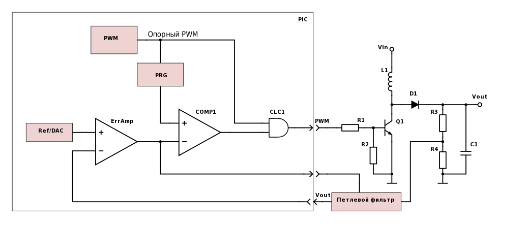
Fig.9 PWM controller SMPS in the voltage control mode with proportional control.
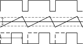
Fig.10. Work diagrams of the PWM controller with voltage control
Current Control (Current Mode)
This method eliminates the drawback of the voltage control mode. In this method, the controller receives a second feedback loop. The internal fast loop serves to control the current of the power switch (inductance) at each cycle of its activation. When a signal is applied to the opening of the power key, the current through the inductance, and hence through the power key, begins to grow linearly. When the threshold is reached, the power switch opens, and the output of the inductance through the diode begins. By time or by detecting zero current in the inductance (in continuous current or critical conductivity mode, CCrM) the cycle repeats.
Since the power switch opens when a peak current is reached, the stored energy in the inductance is constant regardless of the input voltage (a change in the input voltage affects the charge rate). The second loop of the regulation loop controls the output voltage.
Current control with hysteresis control: similar to the voltage control method — the PWM control of the power switch is performed on / off depending on the output voltage.

Fig.11a. PWM controller with current control with hysteresis control. Isence - control of the peak current Is through the inductance, Vout - check the output voltage, blocking the control PWM when the output voltage is exceeded. Option with a fixed output voltage and output voltage adjustment.
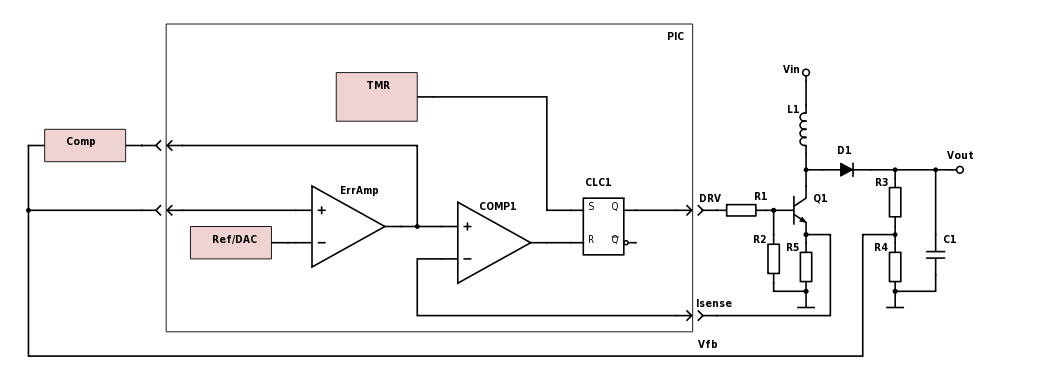
Fig. 11b. PWM controller and output topology option for step-up converter with peak current control.
Proportional control current control
With this control method, the variable PWM duty cycle depends on the output voltage and the active feedback filter.
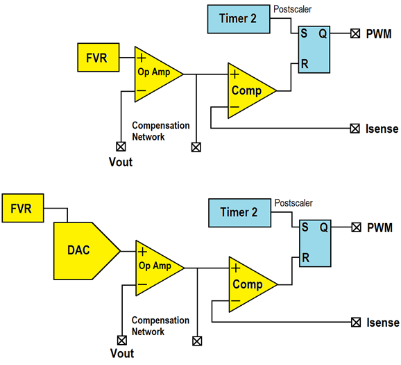
Fig. 12. PWM controller with current control with proportional control. Option with fixed and with adjustable output voltage.
In this method, the instability of the reverse loop is observed when the duty cycle is higher than 50% (the appearance of lasing at the frequency ½ Fswx depends on the noise at Vin or Vout). This process is well studied and the problem is solved by reducing the gain in the feedback loop, which can be achieved in two ways (Fig. 13):
- adding sawtooth to Isense;
- subtracting the sawtooth voltage from the loop filter output.
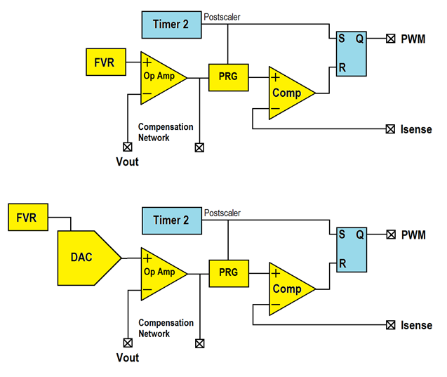
Fig.13. Add a sawtooth voltage shaping module (PRG) to the PWM controller to eliminate the instability of the feedback loop. Option with fixed and with adjustable output voltage.
Microchip controllers for energy converters, as part of the CIP, have a programmable ramp generator (Programmable Ramp Generator, PRG or Slope Compensation).
The PRG module allows you to generate a sawtooth voltage with independent adjustment of the front and fall, as a triggering signal can be used various internal and external signals.
To be continued...
Further:
Synchronous converter
Complementary signal generator
Multiphase alternating (interleave) PWM control
Automation of functions
Controller program
Debugging
')
Source: https://habr.com/ru/post/370637/
All Articles