Automatic room lighting based on Arduino controller
Good afternoon, dear readers, continuing the topic of the introduction of Arduino controllers, I would like to share with you my version of the automatic room lighting project. The article is provided more for newcomers like me than for experienced radio amateurs. Perhaps for someone this article will become the basis for their own projects, well, I will be pleased to read the strict criticism, your options for performance or just support in the comments.
The goal of the project: to mount two circuits for lighting the room on the second floor of the house, provided that it is controlled manually and automatically, at minimal cost.
As a motion sensor, the choice fell on the HC-SR50 pyroelectric infrared sensor, primarily due to the large detection angle, of the order of 120 degrees. We will not dwell on it in more detail, the only thing to say is that the jumper on the sensor is set to H. In this mode, each time the sensor triggers, a logical unit remains at the output. By the number of sensors, it all depends on the room itself, in my case two is quite enough.
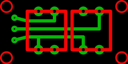
The signal from the sensors will come to one of two relays in one module, which will include the central lighting circuit, but in manual mode we will manage two relays. One is responsible for the central, the second for the peripheral circuit.
')
One of the conditions of automatic control will be to check the level of illumination outdoors. We will do this with the help of a sensor based on the LM393 chip.
To control in manual mode, we will assemble a small board with two clock buttons for easy installation.

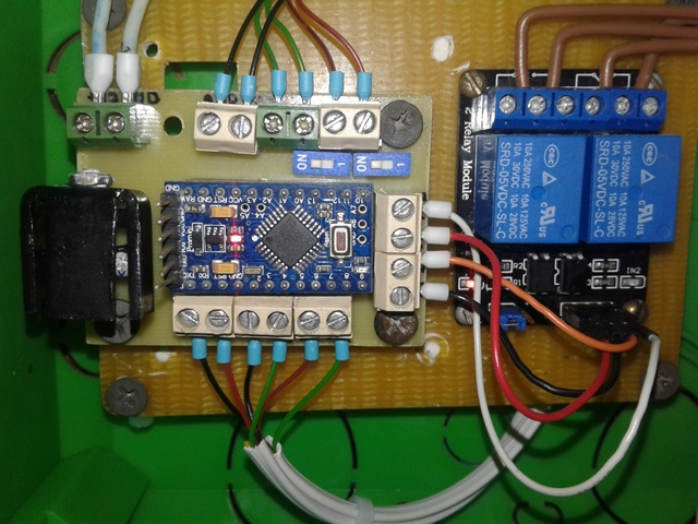
The jumper JD-VCC - VCC is removed, if a separate power supply is applied to the relay coil, as I understand it, this is done for galvanic isolation. To switch the relay, inputs IN1 or IN2 must be pulled to the ground.

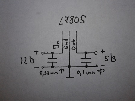
The power supply at my disposal was only the voltage of 220 AC and 12 DC. Therefore, to power the controller itself, relays and sensors using a simple scheme to reduce the voltage to five volts.
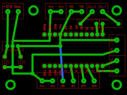
The boards are drawn in the Sprint-Layout program, quite simple and in fact the controller board is needed in order to conveniently connect signals.
The boards are made by everyone's favorite LUT technology.

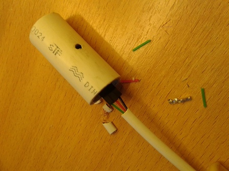
To protect the illumination sensor from light from the room side, in order to prevent the sketch algorithm from working incorrectly, it was decided to hide it in a piece of polypropylene tube. Hole in the end for the possibility of adjusting the sensor.
Sensors are hidden in a small plastic box.
All cables, with the exception of the branches to the sensors, are hidden in plastic boxes.

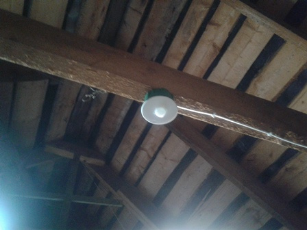
View mounted central shield.

The resulting project has satisfied the goal, as when working in automatic mode, for example, during a short stay in the room, and in manual mode while always in the room when there is no movement.
During the operation of the automation, no failures or remarks were noticed.
Thanks for paying attention.
References:
Automatic staircase lighting
The goal of the project: to mount two circuits for lighting the room on the second floor of the house, provided that it is controlled manually and automatically, at minimal cost.
Planning
As a motion sensor, the choice fell on the HC-SR50 pyroelectric infrared sensor, primarily due to the large detection angle, of the order of 120 degrees. We will not dwell on it in more detail, the only thing to say is that the jumper on the sensor is set to H. In this mode, each time the sensor triggers, a logical unit remains at the output. By the number of sensors, it all depends on the room itself, in my case two is quite enough.
The signal from the sensors will come to one of two relays in one module, which will include the central lighting circuit, but in manual mode we will manage two relays. One is responsible for the central, the second for the peripheral circuit.
')
One of the conditions of automatic control will be to check the level of illumination outdoors. We will do this with the help of a sensor based on the LM393 chip.
To control in manual mode, we will assemble a small board with two clock buttons for easy installation.
The jumper JD-VCC - VCC is removed, if a separate power supply is applied to the relay coil, as I understand it, this is done for galvanic isolation. To switch the relay, inputs IN1 or IN2 must be pulled to the ground.
Preparation for installation
The power supply at my disposal was only the voltage of 220 AC and 12 DC. Therefore, to power the controller itself, relays and sensors using a simple scheme to reduce the voltage to five volts.
The boards are drawn in the Sprint-Layout program, quite simple and in fact the controller board is needed in order to conveniently connect signals.
The boards are made by everyone's favorite LUT technology.
To protect the illumination sensor from light from the room side, in order to prevent the sketch algorithm from working incorrectly, it was decided to hide it in a piece of polypropylene tube. Hole in the end for the possibility of adjusting the sensor.
Drawing a sketch
Sketch
// .
// .
#define Sensor_1 10 // -SR501.
#define Sensor_2 11 // -SR501.
#define D0 3 // .
int Relay[2] = {8, 9}; // .
int Button[2] = {5, 6}; // .
// .
boolean Start_Sensor = false; // .
boolean relayEnabled[2] = {true, true}; // .
boolean buttonWasUp[2] = {true, true}; // .
unsigned long previousMillis = 0; /*
. */
unsigned long activateTime; // .
int value = 0; // .
// .
const int T_hold = 10000; // .
const int T_motion = 200; // .

void setup()
{
// .
pinMode(D0, INPUT); // - .
for (int i = 0; i < 2; ++i)
{
pinMode(Relay[i], OUTPUT); // - .
pinMode(Button[i], INPUT_PULLUP); // - .
digitalWrite(Relay[i], relayEnabled[i]); /* ,
. */
}
}

void loop()
{
if(digitalRead(D0)) // " ?"
{
Sensor_Work();
if (relayEnabled[0] == true && Start_Sensor == true)
// 1 () .
{
relayEnabled[0] = false; // ().
digitalWrite(Relay[0], relayEnabled[0]); // .
activateTime = millis(); // .
while((millis() - activateTime) < T_hold)
{
// .
}
relayEnabled[0] = true; // ().
digitalWrite(Relay[0], relayEnabled[0]); // .
}
}
// , .
for (int i = 0; i < 2; ++i)
{
boolean buttonIsUp = digitalRead(Button[i]);
// (&&) ...
if (buttonWasUp[i] && !buttonIsUp)
{
/* , (),
,
*/
delay(10);
// .
buttonIsUp = digitalRead(Button[i]);
if (!buttonIsUp)
{
// ...
relayEnabled[i] = !relayEnabled[i]; // .
digitalWrite(Relay[i], relayEnabled[i]); // .
}
}
// .
buttonWasUp[i] = buttonIsUp;
}
}

void Sensor_Work() // .
{
if (digitalRead(Sensor_1) == HIGH || digitalRead(Sensor_2) == HIGH) /*
. */
{
// .
if (millis() - previousMillis > T_motion)
{
previousMillis = millis();
value++;
}
}
else
{
Start_Sensor = false; // .
value = 0;
}
if(value >= 10)
{
Start_Sensor = true; // .
value = 0;
}
}
Installation
Sensors are hidden in a small plastic box.
All cables, with the exception of the branches to the sensors, are hidden in plastic boxes.
View mounted central shield.
Total
The resulting project has satisfied the goal, as when working in automatic mode, for example, during a short stay in the room, and in manual mode while always in the room when there is no movement.
During the operation of the automation, no failures or remarks were noticed.
Equipment
| Arduino Pro Mini Atmega 328 5 V 16 MHz Controller | one |
| Pyroelectric infrared sensor HC-SR501 | 2 |
| Light sensor on the LM393 chip | one |
| Voltage stabilizer L7805CV | one |
| 0.33 uF ceramic capacitor | one |
| Ceramic condenser 0.1 microfarad | one |
| PBS 1 × 40 2.54 socket | one |
| SWD1-1 switch | 2 |
| Two-pin screw terminal | 9 |
| Glass fiber 61 × 46 mm | one |
| Glass fiber 40 × 20 mm | one |
| Clock Button | 2 |
| Textolite | one |
| Fluorescent lamp Camelion WL-4002, 16 W | 12 |
| Ceiling lamp with two incandescent lamps | one |
| Junction box | eight |
| PUNP cable 2 × 2.5 | |
| Cable telephone ShTLP -4 0.12 × 7 | |
| Cable channel (various sizes) | |
| Consumables (glue, glue Moment Crystal, solder, rosin, TAGS flux, tips) | |
| Fasteners (bolts, nuts, screws, dowels, clamps) |
References:
Automatic staircase lighting
Source: https://habr.com/ru/post/370623/
All Articles