New nooLite-F system with feedback and encryption

The other day, the modules of the nooLite-F company Noeotechnica for testing and integration with the Arduino Mega Server arrived at the Hi-Lab.ru laboratory and I offer you a small summary of the new system, your opinion about it and simple Arduino code examples for managing new devices .
This article is one of the first signs on this system and I think that soon you will see many other reports about it, but for now the hottest and most up-to-date first-hand information.
What is nooLite?
For those who didn’t know or forgot, let me remind you that nooLite is a wireless control system for electrical equipment, such as lighting in your house or electrical appliances that can be turned on and off using wireless control panels. The consoles have a lot of options, but mostly they look like ordinary lighting switches. Control blocks that accept commands are small boxes with several wires, some of which are connected to the supply voltage, and some - to the load.
')
Simple and clear. Thanks to this simplicity, the nooLite system has gained popularity and is sold in a large number of online and offline stores. But there is one "but." The nooLite system is good for everyone, but it has one (and even two) significant drawbacks. The first is the lack of serious encryption of transmitted commands and data. For most household applications, this is not very critical, but for many people it is unacceptable from the point of view of security - there is at least a small, but not zero, chance that you will be unlucky and someone of hooligan or criminal considerations decides to open your connection and control your equipment.
The second drawback is the lack of feedback in the system (there is a true pseudo-feedback with the help of special blocks, but this is not very serious). What does it mean? This means that you, having given the command to turn on something, cannot be sure that this command is really carried out, and did not leave a trace on the world air.
This is exactly the new version of the system called nooLite-F. Talk of the need to release a new version has been going on for a long time, and finally, the first devices of the new series are on sale.
Few technical details
From a technical point of view, the nooLite system is a receiving-transmitting device operating at a frequency of 433 MHz and using amplitude modulation of the transmitted signal. The choice of amplitude modulation is due to the fact that, according to the manufacturer of the system, this is a simple and poorly susceptible to interference method of transmitting commands over a short distance. The system uses PIC controllers (12, 16, 18). The power consumption of devices is small and the consoles and sensors of the system operate on batteries.
In the new system nooLite-F, the operating frequency remains the same, 433 MHz, and more importantly, compatibility with the old version of the equipment has been preserved. That is, you can work with conventional nooLite devices using nooLite-F control modules.
In the new system, the modulation has changed to frequency, but, surprisingly, this does not prevent the new devices from working with old ones that use amplitude modulation. How is this possible? Engineers of the company had to slightly modify the transceiver of new modules to work simultaneously with both types of modulation.
New transceivers have better sensitivity and, as a result, approximately 30% greater communication range.
Security and Encryption
The nooLite-F system uses strong encryption according to the AES standard, which should reliably secure the operation and use of this equipment. In turn, work with encryption required an increase in computational power and made it necessary to switch to PIC 32 controllers. But this is still an energy efficient solution and the units and modules of the system can run on batteries for a long time.
Available equipment
At the moment, three devices of the new system are available for purchase:
- Adapter MTRF-64-USB for control via USB interface from a computer
- MTRF-64 module for control using controllers with UART interface
- Wireless power unit SLF-1-300
We will conduct our experiments with the power block SLF-1-300 and the module MTRF-64.
Only three products are a temporary phenomenon - the company plans to release a whole line of nooLite-F system equipment, including DIN-rail devices.

Power block SLF-1-300
Externally, the power units of the new system are no different from the usual nooLite units. The same neat casing and the same multiple wires for connecting power and load.

The block contents look a bit more interesting. On the left in the picture you can see two microcircuits - one (smaller) is a transceiver microcircuit, exact marking:
MRF49XA
1637
RG3
and the second chip of the controller controlling the unit, precise marking
STI E4 7B572
32F030F4P6
PHL 648 A
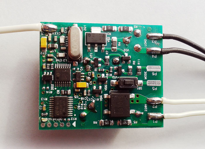
Everything is very compact and neat. This is the long-awaited nooLite with encryption and feedback.
The reverse side of the board is almost completely covered with a radiator.

What is under the radiator can be seen by looking at the power unit board on the side: a few volume parts that do not fit on the reverse side of the board. That's all circuitry.

MTRF-64 module
As I have already said, we will consider the MTRF-64 module with a UART interface, we will not touch its fellow with a USB connection, they are almost identical, except for a few details which will be discussed below. Photo control module:
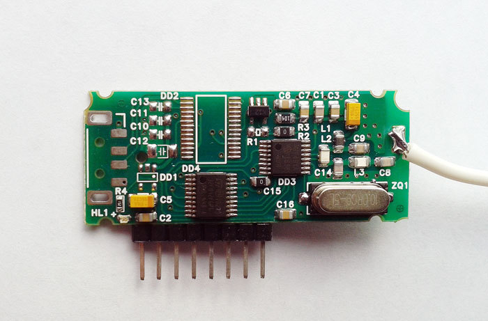
As you can see, it is very similar to the power unit, the same chips, quartz and a few more details. Here is the exact marking of the chips installed on the board. Transceiver:
MRF49XA
1636
M5H
Microcontroller:
STI E4 7B573
32F042F6P6
PHL 648 A
The empty place for the missing chip is the place to install the FTDI USB-UART adapter. The place for installing the USB connector is immediately visible - it is obvious that the same PCB is used for both devices.
Now, a little about connecting the module to microcontrollers in general and to Arduino in particular: for the operation of the module it is enough to connect only four wires - RX, TX, VCC, GND. Simply, as they say, nowhere.
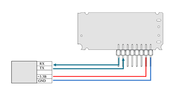
For those who not only read articles, but do something with their own hands, I note that the module is powered strictly from 3.3 volts and its conclusions are not tolerant to 5-volt signals, so keep this in mind and be careful when connecting the module .
A little about the functional module. It has four main modes of operation:
- Transmitter for "old" nooLite system devices. This is an analogue of the functionality of the module nooLite MT1132
- Receiver for “old” nooLite system devices. Analogue of the module nooLite MR1132
- Transmitter for new equipment nooLite-F
- Receiver for new equipment nooLite-F
That is, this module is a universal solution for the interaction of microcontrollers with the nooLite system. Plus, unlike its counterparts, it has the ability to work with 64 channels, instead of 32.
Arduino and nooLite-F
Now let's analyze a simple example that will give you an idea of working with this module in the Arduino environment. By analogy, you can organize work with this module with any other system.
The module interacts with the controlling controller via a serial interface (Serial) at a speed of 9600 bps. Since the MTRF-64 only works with a voltage of 3.3 V, we will set aside our beloved Arduino Mega and take the Arduino Due from the shelf and connect the module to it. Four wiring and everything is ready. For communication with the module we will use Serial3.
- The output of the RX module is connected to the Arduino Due TX3 (14).
- The output of the TX module is connected to the RX3 (15) Arduino Due.
Now you can write a test demo sketch. Let's start with the setup () function.
void setup() { Serial.begin(115200); Serial.println(); Serial.println(F("NooLite-F test")); Serial3.begin(9600); delay(1); bootOut(); // Commands: // 0 - Off // 2 - On // 4 - Switch // 9 - Unbind //15 - Bind setCommand(0); setChannel(0); setChecksum(); Serial.print(F("CH: ")); Serial.println(TO_MTRF[4]); Serial.print(F("CMD: ")); Serial.println(TO_MTRF[5]); Serial.print(F("CHECKSUM: ")); Serial.println(TO_MTRF[15]); mtrfSend(); delay(100); } We start Serial to display debugging messages and Serial3 to work with the MTRF-64 module. At the start, the module enters the software update mode for 12 seconds and to interrupt this mode we enable the function
void bootOut() { for (byte i = 0; i <= 16; i++) { Serial3.write(BOOT_OUT[i]); } } Which sends magic data to the module, taking it out of the software update mode.
Next, we form the command:
// Commands: // 0 - Off // 2 - On // 4 - Switch // 9 - Unbind //15 - Bind In fact, there are much more teams; you can find a complete description of the protocol and the operation of the module in the document on the manufacturer’s website.
Next, we display test messages about the channel, the command and the checksum of the package. This completes the initial setup () procedure and the sketch enters the infinite loop loop ().
void loop() { //setBind(); //setUnbind(); //setOn(); //setOff(); setSwitch(); delay(1000); } Here are five lines that trigger the sending of a command to the MTRF-64 module. You must select any one command and run the sketch (the other commands must be commented out). You need to start with the command to bind the power block to the setBind () module.
Binding procedure:
- Press the button on the power unit - the LED starts blinking on it
- Run the sketch with the uncommented line setBind ()
- Confirm the binding by pressing the button on the power unit again
Everything, now you comment on the line setBind () and uncomment, for example, the line setSwitch (), start the sketch and the test lamp connected to the power block, starts to flash once a second. This is just a test case and based on this sketch, you can create any system of control of nooLite devices, arbitrarily complex.
A little more about the work of the sketch. The code forms the contents of the TO_MTRF array in accordance with the documentation for MTRF-64, the link to which I gave a little higher. Next, the contents of this array are sent over the serial interface directly to the module.
After that, the response of the module is expected and the FROM_MTRF array is filled with incoming data, then this array is analyzed and pre-programmed decisions are made.
Here is the purpose of the other functions of the test sketch:
setChannel (byte ch) - sets the desired channel number (0 - 63).
setCommand (byte cmd) - sets the desired command.
setChecksum () - calculates the checksum of the package .
mtrfSend () - sending data.
mtrfReceive () - reception and parsing of module responses.
Thus, you can tie and untie devices on any channel, turn on, turn off and switch the light using Arduino and MTRF-64. Let me remind you once again that this is only a demonstration of work and an example for further development.
Full code of the test sketch control MTRF-64 using Arduino
/* * NooLite-F * MTRF-64 test Sketch */ // 0 1 2 3 4 5 6 7 8 9 10 11 12 13 14 15 16 byte BOOT_OUT[17] = {171, 4, 0, 0, 0, 0, 0, 0, 0, 0, 0, 0, 0, 0, 0,175,172}; byte TO_MTRF[17] = {171, 2, 0, 0, 0, 0, 0, 0, 0, 0, 0, 0, 0, 0, 0, 0,172}; byte FROM_MTRF[17]; // void bootOut() { for (byte i = 0; i <= 16; i++) { Serial3.write(BOOT_OUT[i]); } } void setChannel(byte ch) { TO_MTRF[4] = ch; } void setCommand(byte cmd) { TO_MTRF[5] = cmd; } void setChecksum() { TO_MTRF[15] = 0; // for (byte i = 0; i <= 14; i++) { TO_MTRF[15] += TO_MTRF[i]; } } void mtrfSend() { for (byte i = 0; i <= 16; i++) { Serial3.write(TO_MTRF[i]); } delay(50); mtrfReceive(); } void setOff() { setCommand(0); setChecksum(); mtrfSend(); } void setOn() { setCommand(2); setChecksum(); mtrfSend(); } void setSwitch() { setCommand(4); setChecksum(); mtrfSend(); } void setBind() { setCommand(15); setChecksum(); mtrfSend(); } void setUnbind() { setCommand(9); setChecksum(); mtrfSend(); } void setup() { Serial.begin(115200); Serial.println(); Serial.println(F("NooLite-F test")); Serial3.begin(9600); delay(1); bootOut(); // Commands: // 0 - Off // 2 - On // 4 - Switch // 9 - Unbind //15 - Bind setCommand(0); setChannel(0); setChecksum(); Serial.print(F("CH: ")); Serial.println(TO_MTRF[4]); Serial.print(F("CMD: ")); Serial.println(TO_MTRF[5]); Serial.print(F("CHECKSUM: ")); Serial.println(TO_MTRF[15]); mtrfSend(); delay(100); } void loop() { //setBind(); //setUnbind(); //setOn(); //setOff(); setSwitch(); delay(1000); } void printFromMTRF() { Serial.println(); for(byte i = 0; i < 17; i++) { Serial.print(FROM_MTRF[i]); Serial.print(" "); } Serial.println(); } void mtrfReceive() { if (Serial3.available() > 0) { Serial3.readBytes(FROM_MTRF, 17); if (FROM_MTRF[0] == 173 && FROM_MTRF[1] == 2 && FROM_MTRF[16] == 174) { //printFromMTRF(); Serial.print(F("Receive: ")); if (FROM_MTRF[10] != 0 && FROM_MTRF[2] == 0) {Serial.println(F("On!"));} if (FROM_MTRF[10] == 0 && FROM_MTRF[2] == 0) {Serial.println(F("Off!"));} if (FROM_MTRF[2] == 1) {Serial.println(F("Error!"));} } else { Serial.println(F("Receive error or bind")); printFromMTRF(); } } } Conclusion
This brief review did not include a story about many of the functions of the new system, for example, firmware over the air, remote attachment and many other features - everything cannot be covered in one review article, but I am sure that other nooLite-F articles from the set will appear soon fans and enthusiasts of automation.
Now my opinion on the new system nooLite-F. Definitely, this is a big step forward for the company Nootech. The difference between the old system and the new one is big - encryption makes it secure, and the feedback allows you to be confident in the execution of the commands given. And all this brings nooLite to a new level and allows you to build serious automation projects on this system.
Source: https://habr.com/ru/post/370383/
All Articles