And what if teaching pupils at the same time PLIS and microcontrollers? More voluminous picture of the world or balls for videos?
In the past seven years, I was repeatedly approached by teachers of children's circles with the question of what would come up for children in the field of electronics, so that 1) it would be interesting 2) would be converted into a future specialty and 3) would give something qualitatively different than the already established ones among the lego-arduin-and-disassemble-units.
The approach that I would like to propose in this note is to construct devices based on the client board using primitives of different levels of abstraction. Before describing the essence of the proposal, I will give an analogy. Suppose we need to explore the area between city A and city B. From A to B, you can drive a car, considering the area around the road. But it is even better to travel not only by car, but also to sail the same route on a submarine, fly it by plane, walk in some places on foot, and also cut through a piece of the mine in the section between the cities on the tunnel miner. Along the way, the student will receive not only the experience of driving a car, but also an idea of the structure of the subsoil, the marine ecosystem, the customs of the inhabitants and the general map of the area.
Now the essence of the proposal. The student in a few days performs a series of simple electronic projects that have similar functionality, but use different objects as building blocks, including:
')
1. Chips of low degree of integration, with several logical elements in each
2. Programmable logic integrated circuits, tens of thousands of cells with variable logic function
3. Microcontrollers
4. Embedded Processors
As a basic tool for such exercises, selected sites from the popular Harris & Harris textbook, available in Russian, are used, including in the form of an officially free electronic version . In paper form, this book can be ordered here and here :

I note that (3) overlaps in subject matter with the Ardwines, and (4) overlaps with the Rasberry section. (1) has already been introduced in history for teaching schoolchildren, but has limited utility without connecting to other levels through (2). It is (2) and comparison (1) - (2) - (3) that distinguishes this proposal from those already used. All four types of dice can be mounted on the same circuit board, but have a different nature, requiring different methods to work with them.
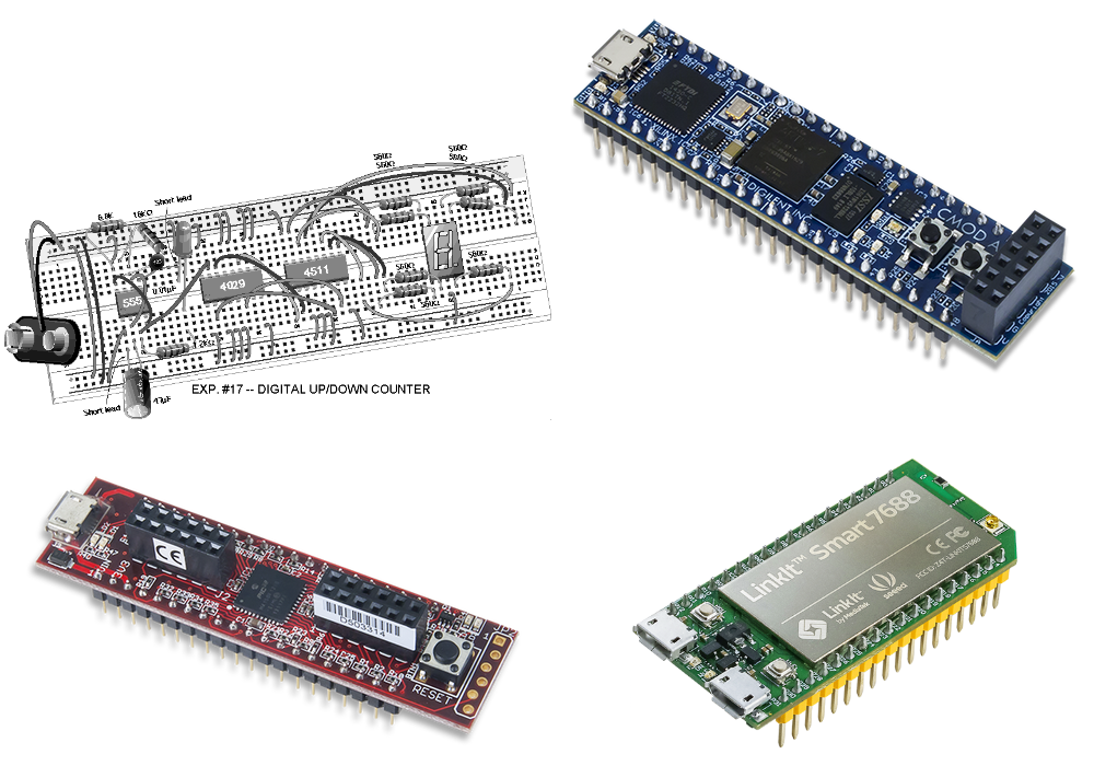
A breadboard for mounting into sockets (breadboard) is a simple device for prototyping electronic circuits without a soldering iron. It includes hundreds of nests, some of which are already connected by metal strips, with the possibility of additional connections with jumpers. Already in the 1970s, some teachers found that it was interesting for children to build on these boards various kinds of crafts based on microcircuits of a small degree of integration: flashing lights, counters, sirens, etc. A technique from California named Gary A. Gibson was able to implement this in schools (see the description of one of these sets here ). Here is an example of such a scheme:
Inside each such chip there are only a few logical elements:

Gibson sets are practical and ideal to “touch” and introduce such concepts as a logical element (gate - AND, OR, NOT), a trigger (D-flip-flop) and a clock signal (clock). Now, in the 21st century, ETron Circuit Labs continues to sell these kits with minor modifications. In Russia, similar sets sells LLC Cyberphysics .
At the same time, in the 1980s, interest in such kits fell, as the industry began to use more microcontrollers than low-integration microcircuits, and the logical smooth transition from individual logic elements to microcontrollers through the design of microcircuits was clearly inaccessible to schoolchildren.
At the same time, in the same 1980s, two technologies emerged which, 20 years later, changed the situation again. One of these technologies is a logical synthesis from the Hardware Description Language (HDL) using the Register Transfer Level (RTL). Another technology is programmable logic integrated circuits (Field Programmable Gate Array - FPGA), matrixes of logic cells, the function of which can be changed by flashing configuration memory. The latter is different from the classical programming, because in the case of FPGA / FPGA, we build a circuit, rather than writing a chain of program instructions.
Now there are inexpensive FPGAs / FPGAs with which cards can be inserted into a prototyping board. Now, instead of physical connections of several logical elements with jumpers, the student can build circuits of tens of thousands of logical elements by changing the FPGA / FPGA configuration. See the note How to start developing iron using FPGAs - step by step instructions :

In addition to simple finite automata and arithmetic devices, a student can build by reconfiguring such a chip and a simple microprocessor - see Chapter 7 in Harris & Harris .
And recently, Digilent (National Instruments) launched another Cmod A7-35T module with a FPGA with a larger Xilinx Artix-7 capacity, which can be used in the industry microprocessor core MIPS microAptiv UP, which is available for free in in the form of a MIPSfpga package (but this is no longer for schoolchildren, but rather for university students):

Finally, you can also insert a module with a microcontroller that can be programmed into C into the breadboard. In this way, you can compare the programming of the embedded processor with the construction of the circuit in the FPGA in the previous exercise. How to program a similar microcontroller, I described at one time in the article How to start working with Microchip PIC32. Part One

I note that for programming Microchip PIC32, you can use both the Arduino-like MPIDE development system and the professional MPLAB X environment in which you can, for example, use RTOS. From my point of view, the difference in the difficulty level to start working with MPIDE and MPLAB X is not large enough to first learn MPIDE, and then MPLAB X. If ultimately a person is going to get professional skills, it is better to start right away with MPLAB X. If Since the goal is to say, to teach humanities to program microcontrollers, it is better to use MPIDE and stay on it.
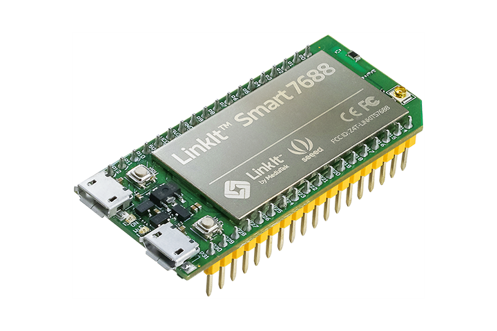
Finally, you can insert a module with a built-in processor, which can run a version of Linux - OpenWrt , into a prototyping board. Flashing lights on a computer with built-in Linux is also a good exercise to understand what additional levels this adds (drivers, kernel / user mode, etc.):
In the end, the student can be given a lecture on the entire sequence of designing and manufacturing microchips from the specification to the microcircuit at the factory. This will connect his FPGA / FPGA exercises on an inexpensive student board with mass production. To do this, you can make popular science squeeze out of the course. Specialized nano-level integrated circuits :

So, if I had the task to drive schoolchildren at a gallop around Europe in a few days, then I would do it this way:
Day 1 before lunch. Assembling combinational circuits on a breadboard with chips of a small degree of integration:
1.1 Exercise with logical elements AND, OR, NOT
1.2 Theft with adder and 7-segment indicator
Day 1 after lunch. Assembly of sequential circuits on a breadboard with chips of low degree of integration:
1.2 Exercise with a clock signal generator 555 and D-trigger
1.3 Exercise with a counter, running lights and a 7-segment indicator
Day 2. Repeat Day 1, but with Verilog and FPGA
Day 3. Repeating day 1, but with a microcontroller and C
Day 4. Repeating day 1, but with an embedded processor and Linux OpenWrt
Day 5. Finish previous days + lecture throughout the electronics industry
The approach that I would like to propose in this note is to construct devices based on the client board using primitives of different levels of abstraction. Before describing the essence of the proposal, I will give an analogy. Suppose we need to explore the area between city A and city B. From A to B, you can drive a car, considering the area around the road. But it is even better to travel not only by car, but also to sail the same route on a submarine, fly it by plane, walk in some places on foot, and also cut through a piece of the mine in the section between the cities on the tunnel miner. Along the way, the student will receive not only the experience of driving a car, but also an idea of the structure of the subsoil, the marine ecosystem, the customs of the inhabitants and the general map of the area.
Now the essence of the proposal. The student in a few days performs a series of simple electronic projects that have similar functionality, but use different objects as building blocks, including:
')
1. Chips of low degree of integration, with several logical elements in each
2. Programmable logic integrated circuits, tens of thousands of cells with variable logic function
3. Microcontrollers
4. Embedded Processors
As a basic tool for such exercises, selected sites from the popular Harris & Harris textbook, available in Russian, are used, including in the form of an officially free electronic version . In paper form, this book can be ordered here and here :
I note that (3) overlaps in subject matter with the Ardwines, and (4) overlaps with the Rasberry section. (1) has already been introduced in history for teaching schoolchildren, but has limited utility without connecting to other levels through (2). It is (2) and comparison (1) - (2) - (3) that distinguishes this proposal from those already used. All four types of dice can be mounted on the same circuit board, but have a different nature, requiring different methods to work with them.
A breadboard for mounting into sockets (breadboard) is a simple device for prototyping electronic circuits without a soldering iron. It includes hundreds of nests, some of which are already connected by metal strips, with the possibility of additional connections with jumpers. Already in the 1970s, some teachers found that it was interesting for children to build on these boards various kinds of crafts based on microcircuits of a small degree of integration: flashing lights, counters, sirens, etc. A technique from California named Gary A. Gibson was able to implement this in schools (see the description of one of these sets here ). Here is an example of such a scheme:
Inside each such chip there are only a few logical elements:
Gibson sets are practical and ideal to “touch” and introduce such concepts as a logical element (gate - AND, OR, NOT), a trigger (D-flip-flop) and a clock signal (clock). Now, in the 21st century, ETron Circuit Labs continues to sell these kits with minor modifications. In Russia, similar sets sells LLC Cyberphysics .
At the same time, in the 1980s, interest in such kits fell, as the industry began to use more microcontrollers than low-integration microcircuits, and the logical smooth transition from individual logic elements to microcontrollers through the design of microcircuits was clearly inaccessible to schoolchildren.
At the same time, in the same 1980s, two technologies emerged which, 20 years later, changed the situation again. One of these technologies is a logical synthesis from the Hardware Description Language (HDL) using the Register Transfer Level (RTL). Another technology is programmable logic integrated circuits (Field Programmable Gate Array - FPGA), matrixes of logic cells, the function of which can be changed by flashing configuration memory. The latter is different from the classical programming, because in the case of FPGA / FPGA, we build a circuit, rather than writing a chain of program instructions.
Now there are inexpensive FPGAs / FPGAs with which cards can be inserted into a prototyping board. Now, instead of physical connections of several logical elements with jumpers, the student can build circuits of tens of thousands of logical elements by changing the FPGA / FPGA configuration. See the note How to start developing iron using FPGAs - step by step instructions :
In addition to simple finite automata and arithmetic devices, a student can build by reconfiguring such a chip and a simple microprocessor - see Chapter 7 in Harris & Harris .
And recently, Digilent (National Instruments) launched another Cmod A7-35T module with a FPGA with a larger Xilinx Artix-7 capacity, which can be used in the industry microprocessor core MIPS microAptiv UP, which is available for free in in the form of a MIPSfpga package (but this is no longer for schoolchildren, but rather for university students):
Finally, you can also insert a module with a microcontroller that can be programmed into C into the breadboard. In this way, you can compare the programming of the embedded processor with the construction of the circuit in the FPGA in the previous exercise. How to program a similar microcontroller, I described at one time in the article How to start working with Microchip PIC32. Part One
I note that for programming Microchip PIC32, you can use both the Arduino-like MPIDE development system and the professional MPLAB X environment in which you can, for example, use RTOS. From my point of view, the difference in the difficulty level to start working with MPIDE and MPLAB X is not large enough to first learn MPIDE, and then MPLAB X. If ultimately a person is going to get professional skills, it is better to start right away with MPLAB X. If Since the goal is to say, to teach humanities to program microcontrollers, it is better to use MPIDE and stay on it.
Finally, you can insert a module with a built-in processor, which can run a version of Linux - OpenWrt , into a prototyping board. Flashing lights on a computer with built-in Linux is also a good exercise to understand what additional levels this adds (drivers, kernel / user mode, etc.):
In the end, the student can be given a lecture on the entire sequence of designing and manufacturing microchips from the specification to the microcircuit at the factory. This will connect his FPGA / FPGA exercises on an inexpensive student board with mass production. To do this, you can make popular science squeeze out of the course. Specialized nano-level integrated circuits :
So, if I had the task to drive schoolchildren at a gallop around Europe in a few days, then I would do it this way:
Day 1 before lunch. Assembling combinational circuits on a breadboard with chips of a small degree of integration:
1.1 Exercise with logical elements AND, OR, NOT
1.2 Theft with adder and 7-segment indicator
Day 1 after lunch. Assembly of sequential circuits on a breadboard with chips of low degree of integration:
1.2 Exercise with a clock signal generator 555 and D-trigger
1.3 Exercise with a counter, running lights and a 7-segment indicator
Day 2. Repeat Day 1, but with Verilog and FPGA
Day 3. Repeating day 1, but with a microcontroller and C
Day 4. Repeating day 1, but with an embedded processor and Linux OpenWrt
Day 5. Finish previous days + lecture throughout the electronics industry
Source: https://habr.com/ru/post/370163/
All Articles