Cloud sensor for observatory

In my opinion, one of the most important related tasks of terrestrial observational astronomy is the control of astroclimate.
Astroclimate is a combination of atmospheric factors affecting the quality of astronomical observations, by distorting the radiation of celestial objects.
(note, there are a lot of images under the cut!)
These factors include, for example, the refractive index of air, depending on its temperature. A change in air temperature by 1 degree Celsius changes its index of refraction so much that it already affects the image quality. In this connection, telescopes try to locate above temperature non-uniformities - on mountain peaks. The height of the towers themselves is also chosen such that the telescope is located above local inhomogeneities.
')
Also an important factor is the wind, which can cause mixing of small inhomogeneities in the air, thereby leading to an unfocused image.
And probably one of the most important factors is the number of clear days per year.
Cloudy sky completely blocks the operation of the telescope and may be a messenger
precipitation, which is dangerous for the equipment.
In addition to natural factors, there are also man-made. This is the illumination from the cities, emissions into the atmosphere, local heating of the air.
Before the construction of the observatory, special research astroclimatic groups measure and analyze all these factors for a certain period of time, after which they render their verdict and allow the installation of telescopes in this place or start searching for another place.
But astroclimate is not a constant thing and unfortunately can sometimes change a lot, often due to a person. Therefore, constant monitoring is necessary.
I propose to talk about one of the most frequently changing factor - cloud cover. Particularly acute is the question of cloud control in the case of a remotely controlled observatory, when it is impossible to simply go outside and see what is in the sky.
Some help here can provide a sky view camera - a sensitive wide-angle camera aimed at the zenith.

(the picture from the camera is not mine, taken as an example. there is a meteor in the frame :))
But a good camera with a lens is not the most cost-effective solution, which imposes additional requirements on related equipment and communication channel. In addition, in the case of an automated observatory, frame analysis to identify clouds is also not a trivial task.
In addition to the camera, observatories around the world successfully use sensors that make it easy to obtain a sufficiently accurate numerical estimate of the sky clarity at night as the only monitoring device for clouds. In addition, data from sensors is very easy to accumulate and subsequently carry out a historical analysis of astroclimate.
Some theory
During the day, solar radiation warms the surface of the Earth and everything on it - buildings, roads, water, etc. All stored energy is subsequently re-emitted in the form of the same heat (infrared radiation).
If the earth did not have an atmosphere, then all the stored energy without any obstacles would be radiated into space. But fortunately, our planet has an atmosphere :)
The atmosphere includes various gases, aerosols, dust particles and water vapor. The infrared radiation emitted by the Earth is actively absorbed by water vapor, heating the atmosphere itself (this allows us to keep our planet warm enough for life to exist). Clouds are known to be composed of water vapor. Accordingly, the more of this vapor in the atmosphere (more clouds) - the higher the temperature. Conversely, the clearer and clearer the sky, the lower the temperature. Like the temperature of any other body - the temperature of the atmosphere (sky) can be measured. Speaking of temperature, they mean the temperature of the air column (more precisely, a cone, the angle of the solution of which is equal to the angle of "view" of a particular sensor). The height of this pillar is about 10-15 km, i.e. to the troposphere - the atmospheric layer, where the weather is “done”.
Actually, the sky temperature always means how much this measured cone-shaped area is warmer than the surrounding space (the temperature of which is close to absolute zero) and how much cooler it is than cumulus clouds. This should not be confused with the actual temperature of the air at a certain altitude.
(At an altitude of 10 km, as I think, many people know, the actual temperature can reach up to -50 degrees Celsius).
The temperature of the ambient air at the point of installation of the sensor is chosen as the reference. The greater the difference between the ambient temperature and the measured temperature of the sky - the clearer the sky. Usually a difference of 20 degrees indicates a very clean atmosphere, but if the difference is less than five degrees, the sky is tightly covered with clouds.
Contact methods for measuring the temperature of the sky are obviously not suitable here, so they use infrared thermometers.
There are hand thermometers similar to the one in the photo below.
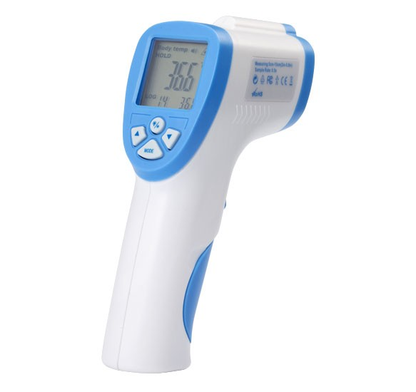
This is a kind of single-pixel "thermal imager", the angle of view, which is primarily determined by the built-in Fresnel lens.
You can conduct a simple experiment and send the device to the sky: to a clean area and to the cloud - the result will be noticeable immediately.
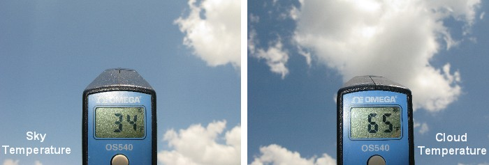
(image credit: Forrest M. Mims III., mynasadata.larc.nasa.gov)
Cloud sensor design
Having dealt with the temperature of the sky and the measurement, I propose to consider the simple design of the corresponding sensor capable of operating in an autonomous automatic mode.
The heart of the device is an Melexis infrared thermometer - MLX90614, which is quite simple to buy.

The thermometer is made in a convenient hermetic enclosure, resembling the case of some domestic operational amplifiers.
The device communicates with the outside world using an i2c-compatible SMBus bus, with some small nuances, which I will discuss next.
There is also an autonomous analog mode, when the output of the device is a PWM signal, with a duty cycle depending on the measured temperature. It may be useful when creating devices like a thermostat.
The device can measure temperature using two sensors - a classic thermocouple and an infrared sensor. There are also versions equipped with two IR sensors at once.
Some characteristics of the device

Pinout

The SDA data line is also used to output the PWM signal in the appropriate mode.
By default, the device should work in SMBus mode, but in my case for some reason PWM turned on. This led to the fact that after connecting, I saw complete chaos on the i2c bus.
To switch the device to SMBus mode, it is sufficient to shortly close the SCL line to earth at the moment the power is applied to the device. Unfortunately, the next time the device is turned on, it will be back in PWM mode. To switch to SMBus mode “forever,” you need to change the parameters in the device's EEPROM.
The cloud sensor is based on the first generation Raspberry Pi B microcomputer.
Of course, it would be possible to get along with the simplest avr microcontroller, but in my case the sensor is part of a more complex instrument — a universal allsky camera, which I will definitely write about. In my project, I use the Raspbian Jessie distribution with the kernel version 4.4. Everything described below is valid for this version of the board and for this version of the OS.
The network has a large amount of information about connecting the MLX90614 to microcontrollers and there is usually no problem here, but there is not enough information about Raspberry and you can easily find various rakes. I hope that this article will help someone not to step on them :)
So, everything is connected very simply.

Capacitor C1 - ceramic, its use is mandatory.
Resistors R1 and R2 are 4K7, optional, since The Raspberry Pi has its suspenders on the i2c bus.
But if the line to mlx is long enough - it is better to install resistors. In my case, another device is hanging right next to the bus, in which there are also such resistors, so for mlx I didn’t put any braces. I use the three-volt version of mlx90614 so in this case the power comes from the 3.3 volt line. In the case of a five-volt, it may be necessary to agree on the levels in order not to damage the Raspberry.
SMBus
I would like to say separately about the tires SMBus and I2C. Both buses, in our case (power supply 3.3 volts), are electrically and signal compatible, so you can work with the MLX90614 as with a regular i2c device. There are also differences in the maximum operating speeds, but this can be neglected in this case.
Work with the device
For Raspberry Pi, there are two basic ways to communicate with i2c devices - using the i2c hardware bus, using the i2c_bcm2708 driver and the libi2c-dev library, or using the popular bcm2835 library that emulates the i2c protocol programmatically, with the same GPIO2 and GPIO3 at the desired interval. By default, the device's i2c address is 0x5A.
Looking ahead, I would say that there were no problems with bcm2835 and the MLX90614 sensor started working right away, but I didn’t like this method, why programmatically emulate existing hardware on a computer with very limited resources. It was decided to work through the driver i2c_bcm2708.
First of all, you should make sure that the i2c_bcm2708 module is loaded by executing the lsmod command, if the module is not in the list, you need to load it with the command
sudo modprobe i2c_bcm2708 and then add the line i2c_bcm2708 to the end of the / etc / modules file, this is necessary in order for the module to load when the system starts.
After loading the module, two devices will become available - / dev / i2c-0 and / dev / i2c-1
The first refers to the zero bus i2c, the second, respectively, to the first. In the case of the first generation Raspberry Pi, the zero bus is not soldered on the board, the first GPIO mapped to the comb, so all the work goes through / dev / i2c-1
Now if you run the command
i2cdetect -y1 (supplied in the package libi2c-dev, y 1 - i2c bus number) you can see the following (provided that we no longer have any i2c devices).
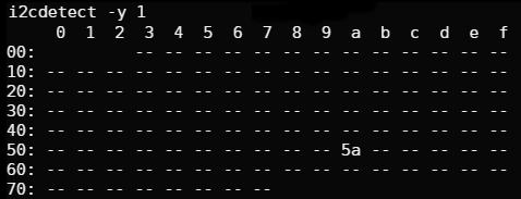
The device with address 5a is our MLX90614. If you see just a chaotic array of numbers - your mlx works in PWM mode to switch - remove power from the device, press the SCL line to the “ground” and reapply power, after which SCL can be released. After that, the device should switch to SMBus mode and the output of i2cdetect will become correct.
Next, I will show how you can change the parameters in the EEPROM and fix this situation.
Working with the device is very simple. We write the simplest program in C
Simplest example
// #include <sys/ioctl.h> #include <sys/types.h> #include <sys/stat.h> #include <fcntl.h> #include <stdio.h> #include <errno.h> #include <string.h> #include <linux/i2c-dev.h> /// int main() { int fdev = open("/dev/i2c-1", O_RDWR); // i2c if (fdev < 0) { fprintf(stderr, "Failed to open I2C interface %s Error: %s\n", dev_path, strerror(errno)); return -1; } unsigned char i2c_addr = 0x5A; // , 0x5A if (ioctl(fdev, I2C_SLAVE, i2c_addr) < 0) { fprintf(stderr, "Failed to select I2C slave device! Error: %s\n", strerror(errno)); return -1; } // , if (ioctl(fdev, I2C_PEC, 1) < 0) { fprintf(stderr, "Failed to enable SMBus packet error checking, error: %s\n", strerror(errno)); return -1; } // - , SMBus READ i2c_data data; char command = 0x06; // 0x06 . struct i2c_smbus_ioctl_data sdat = { .read_write = I2C_SMBUS_READ, .command = command, .size = I2C_SMBUS_WORD_DATA, .data = &data }; if (ioctl(fdev, I2C_SMBUS, &sdat) < 0) { fprintf(stderr, "Failed to perfom I2C_SMBUS transaction, error: %s\n", strerror(errno)); return -1; } // , double temp = (double) data.word; temp = (temp * 0.02)-0.01; temp = temp - 273.15; // printf("Tamb = %04.2f\n", temp); return 0; } Compile:
gcc test.c -l -o test Run:
sudo ./test ... and we get the error “ Failed to perfom I2C_SMBUS transaction, error: bad message ”
This is a response from mlx90614, the device does not understand our request.
In trying to figure out what's going on, I decided to take a logic analyzer and see how it is exchanged with the device.
The datasheet provides an example of a normal exchange on the SMBus bus, reading, as in our case.
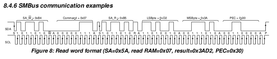
The logic analyzer showed the following picture.

It can be seen that after executing the write command and sending data, an unnecessary stop bit (red dot) is added before sending a read request. It sort of breaks our single package into two separate defective packages. Of course, the device does not understand such a request.
Having tried to repeat the same thing with the bcm2835 software library, I saw that everything works out correctly.

So I somehow did not use the hardware driver api. As a result, after a certain tinkering in the kernel code and digging on the Rasperry Pi forum, it turned out that in order for everything to work, the so-called combined write-read mode should be activated in the driver. In this mode, the driver does not break one packet with two read-write commands into two independent ones. To activate it, you need to run the command from root:
echo -n 1 > /sys/module/i2c_bcm2708/parameters/combined Writing zero in combined respectively turns off this mode.
Now, after switching on the mode, if we run our previous example again, we should get an answer.
sudo ./test Tamb = 19.4 Everything is working! Now you can write a full-fledged junk to work with the device.
The datasheet describes well all the EEPROM and RAM addresses for reading and writing values and parameters.

As it is not difficult to guess - the PWCTRL register allows you to enable and disable the same PWM mode.
Description of the register bits from the datasheet.

Accordingly, to turn off the PWM mode, you must set the first bit of the PWCTRL register to 0.
The reading of temperature values occurs from the RAM by devices.

As you can see from here you can read thermocouple, the first and second (if available) channel of the IR sensor, in the form of raw data and in the form of temperature.
Create a header file with the necessary addresses, mlx_addrs.h
mlx_addrs.h
// RAM #define MLX90614_RAWIR1 0x04 #define MLX90614_RAWIR2 0x05 #define MLX90614_TA 0x06 #define MLX90614_TOBJ1 0x07 #define MLX90614_TOBJ2 0x08 // EEPROM #define MLX90614_TOMAX 0x20 #define MLX90614_TOMIN 0x21 #define MLX90614_PWMCTRL 0x22 #define MLX90614_TARANGE 0x23 #define MLX90614_EMISS 0x24 #define MLX90614_CONFIG 0x25 #define MLX90614_ADDR 0x2E #define MLX90614_ID1 0x1C #define MLX90614_ID2 0x1D #define MLX90614_ID3 0x1E #define MLX90614_ID4 0x1F And the complete source code is applied to work with the MLX90614 device.
mlx90614.c
#include <sys/ioctl.h> #include <sys/types.h> #include <sys/stat.h> #include <stdint.h> #include <fcntl.h> #include <unistd.h> #include <string.h> #include <stdio.h> #include <getopt.h> #include <stdlib.h> #include <linux/i2c-dev.h> #include <errno.h> #include "mlx_addrs.h" // buffer for data reading or writing typedef union i2c_smbus_data i2c_data; static int DEBUG_MODE = 0; extern const char* __progname; /// int get_device(const int bus_num, const unsigned char i2c_addr) { char dev_path[11] = { 0 }; // construct path to i2c device snprintf(dev_path, 11, "/dev/i2c-%i", bus_num); if (DEBUG_MODE) { fprintf(stderr, "Opening i2c interface %s\n", dev_path); } int fdev = open(dev_path, O_RDWR); if (fdev < 0) { fprintf(stderr, "Failed to open I2C interface %s Error: %s\n", dev_path, strerror(errno)); return -1; } if (DEBUG_MODE) { fprintf(stderr, "Setting up slave address 0x%02X\n", i2c_addr); } // set addr of the slave i2c device if (ioctl(fdev, I2C_SLAVE, i2c_addr) < 0) { fprintf(stderr, "Failed to select I2C slave device! Error: %s\n", strerror(errno)); return -1; } // enable checksums if (ioctl(fdev, I2C_PEC, 1) < 0) { fprintf(stderr, "Failed to enable SMBus packet error checking, error: %s\n", strerror(errno)); return -1; } return fdev; } int talk_to_device(const int fdev, const int read, const char command, i2c_data* data) { // initialize i2c_smus structure for combined write/read request to device struct i2c_smbus_ioctl_data sdat = { .read_write = (read ? I2C_SMBUS_READ : I2C_SMBUS_WRITE), // set operation type: read or write .command = command, // set command, ie register number .size = I2C_SMBUS_WORD_DATA, // set data size, note: mlx supports only WORD .data = data // pointer to data }; if (DEBUG_MODE) { fprintf(stderr, "Perfoming %s request to device, command = 0x%02X\n" , (read ? "I2C_SMBUS_READ" : "I2C_SMBUS_WRITE"), command); } // perfom combined request to device if (ioctl(fdev, I2C_SMBUS, &sdat) < 0) { fprintf(stderr, "Failed to perfom I2C_SMBUS transaction, error: %s\n", strerror(errno)); return -1; } if (DEBUG_MODE) { fprintf(stderr, "Ok, got answer from device\n"); } return 0; } int check_args(const int bus_num, const unsigned char i2c_addr) { if (bus_num > 1 || bus_num < 0) { fprintf(stderr, "Invalid bus number %i, please select 0 or 1\n", bus_num); return -1; } if (i2c_addr == 0) { fprintf(stderr, "Invalid i2c device address, please set proper address of the MLX\n"); return -1; } return 0; } int read_data_from_sensor(const int fdev, const char command) { i2c_data data; if (talk_to_device(fdev, 1, command, &data) < 0) { return -1; } double temp = 0; switch (command) { case MLX90614_TA: case MLX90614_TOBJ1: case MLX90614_TOBJ2: temp = (double) data.word; temp = (temp * 0.02)-0.01; temp = temp - 273.15; printf("%s = %04.2f\n", (command == MLX90614_TA ? "Tamb" : "Tobj"), temp); break; case MLX90614_EMISS: printf("Emissivity correction coefficient = %i\n", data.word); break; case MLX90614_PWMCTRL: if (!(data.word & (1 << 1))) { printf("PWM mode - disabled\n"); } else { printf("PWM mode - enabled\n"); printf("In order to disable pwm mode - pull down SCL for >=1.2 ms and change EEPROM setting.\n"); } break; } return 0; } int write_data_to_sensor(const int fdev, const char command, const unsigned short write_arg) { i2c_data msg; // get current value of the register if (talk_to_device(fdev, 1, command, &msg) < 0) { return -1; } unsigned short current_val = msg.word; if (DEBUG_MODE) { fprintf(stderr, "EEPROM cell = 0x%02X current value = 0x%04X\n", command, current_val); } msg.word = 0x0; if (DEBUG_MODE) { fprintf(stderr, "Erasing EEPROM cell = 0x%02X\n", command); } // provide some time for device usleep(1000); if (talk_to_device(fdev, 0, command, &msg) < 0) { fprintf(stderr, "Unable to erase EEPROM cell\n"); return -1; } // delay between eeprom erasing and writing new value // without this delay writing to device may fail usleep(5000); if (command == MLX90614_ADDR) { msg.word = 0xFFFF; msg.word = msg.word << 8 | write_arg; // MLX devices uses LSByte only for address, other bits are ignored } else if(command == MLX90614_PWMCTRL) { if (write_arg) { // enable PWM bit current_val |= (1 << 1); } else { //disable PWM bit current_val &= ~(1 << 1); } msg.word = current_val; } else { msg.word = write_arg; } if (DEBUG_MODE) { fprintf(stderr, "Trying to store value = 0x%04X to the EEPROM cell = 0x%02X\n", msg.word, command); } if (talk_to_device(fdev, 0, command, &msg) < 0) { fprintf(stderr, "Unable to write to EEPROM\n"); return -1; } usleep(5000); if (command == MLX90614_ADDR) { printf("MLX device address succesfully changed to 0x%X\n", msg.word); printf("Please, power off and power on again the device to apply changes\n"); } else if (command == MLX90614_EMISS) { printf("Warning! Emissivity correction coefficient was changed to %i\n", msg.word); } else if (command == MLX90614_PWMCTRL) { printf("PWM mode is now %s\n", (write_arg ? "enabled" : "disabled")); } return 0; } void show_usage() { printf("Usage\n"); printf("\t%s --bus [0-1] --i2c_addr [0x00-0x7F] command|command=values wflag\n", __progname); printf("\n"); printf("\t\tb, --bus\t\t- set i2c bus number (0 for Raspbery PI model A, 1 for Raspberry PI model B, default is 0)\n"); printf("\t\tc, --i2c_addr\t\t- set slave device address (default = 0x5A)\n"); printf("\t\tr, --new_addr=ADDR\t- set new i2c ADDR for the device\n"); printf("\t\tw, --write\t\t- perfom writing to the device (wflag)\n"); printf("\t\ti, --get_ir_temp\t- get temperature in C from the infrared sensor\n"); printf("\t\ta, --get_ambient_temp\t- get temperature in C from the PTAT element\n"); printf("\t\te, --emissivity_coefficient\t- get value of the emissivity coefficient\n"); printf("\t\t--emissivity_coefficient=VALUE\t- set new VALUE for emissivity coefficient, use with --write argument\n"); printf("\t\tp, --pwm_mode\t\t- check current state of the PWM\n"); printf("\t\t--pwm_mode=1|0\t\t- disable (0) or enable (1) PWM mode, use with --write argument\n"); } int main(int argc, char **argv) { int bus_num = 0; unsigned char i2c_addr = MLX90614_I2CADDR; int op_read = 1; int write_arg_set = 0; unsigned char command = 0x00; unsigned short write_arg = 0x00; static struct option long_options[] = { { "help", no_argument, NULL, 'h' }, { "bus", required_argument, NULL, 'b' }, { "i2c_addr", required_argument, NULL, 'c' }, { "new_addr", required_argument, NULL, 'r'}, { "write", no_argument, NULL, 'w' }, { "get_ir_temp", no_argument, NULL, 'i' }, { "get_ambient_temp", no_argument, NULL, 'a' }, { "emissivity_coefficient", optional_argument, NULL, 'e'}, { "pwm_mode", optional_argument, NULL,'p'}, { "debug", no_argument, NULL, 'd' } }; int option_index = 0; int opt = getopt_long(argc, argv, "hbc:r:wiae:p:d", long_options, &option_index); while (opt != -1) { switch (opt) { case 'h': show_usage(); return 0; case 'b': bus_num = atoi(optarg); break; case 'c': i2c_addr = strtol(optarg, NULL, 16); break; case 'r': write_arg = strtol(optarg, NULL, 16);; write_arg_set = 1; command = MLX90614_ADDR; break; case 'w': op_read = 0; break; case 'i': command = MLX90614_TOBJ1; break; case 'a': command = MLX90614_TA; break; case 'e': command = MLX90614_EMISS; if (optarg) { write_arg = atoi(optarg); printf("%i\n", write_arg); write_arg_set = 1; } break; case 'p': command = MLX90614_PWMCTRL; if (optarg) { write_arg = atoi(optarg); write_arg_set = 1; } break; case 'd': DEBUG_MODE = 1; break; default: show_usage(); abort(); } opt = getopt_long(argc, argv, "bc:wiaep", long_options, &option_index); } if (check_args(bus_num, i2c_addr) < 0) { return -1; } if (!op_read && (command == MLX90614_TOBJ1 || command == MLX90614_TA)) { fprintf(stderr, "Read only data!\n"); return -1; } if (!op_read && !write_arg_set) { fprintf(stderr, "Plese set parameter value for writing\n"); return -1; } int fdev = get_device(bus_num, i2c_addr); if (fdev < 0) { return -1; } int res; if (op_read) { res = read_data_from_sensor(fdev, command); } else { res = write_data_to_sensor(fdev, command, write_arg); } close(fdev); return res; } Makefile
CC := gcc PROGRAM = read_mlx90614 SRC := mlx90614.c CFLAGS := -Wall -std=gnu99 TARGET_DIR := /opt/allsky/bin all: $(PROGRAM) $(PROGRAM): $(OBJECTS) $(CC) $(CFLAGS) $(SRC) $(LDFLAG) -o $(PROGRAM) install: mkdir -p $(TARGET_DIR) cp $(PROGRAM) $(TARGET_DIR) cp dht_to_db.sh $(TARGET_DIR) clean: rm -fr $(PROGRAM) $(PROGRAM).o We collect and run:
make Reading the temperature from the IR sensor, i2c bus 1, i2c address 0x5A:
./read_mlx90614 --bus 1 --i2c_addr 0x5a -i Tobj = 21.3 Temperature reading with thermocouple sensor:
./read_mlx90614 --bus 1 --i2c_addr 0x5a -a Tamb = 19.4 Work with the PWM mode. Find out the current mode:
./read_mlx90614 --bus 1 --i2c_addr 0x5a -p PWM mode - enabled Turn off PWM mode:
./read_mlx90614 --bus 1 --i2c_addr 0x5a --pwm_mode=1 -w Turn off PWM mode:
./read_mlx90614 --bus 1 --i2c_addr 0x5a --pwm_mode=0 -w There is also an additional argument - debug, which turns on debugging mode, this allows you to visually see all the interaction with the device.
./read_mlx90614 --bus 1 --i2c_addr 0x5a --pwm_mode=1 -w –debug Opening i2c interface /dev/i2c-1 Setting up slave address 0x5A Perfoming I2C_SMBUS_READ request to device, command = 0x22 Ok, got answer from device EEPROM cell = 0x22 current value = 0x0201 Erasing EEPROM cell = 0x22 Trying to store value = 0x0203 to the EEPROM cell = 0x22 PWM mode is now enabled Since The infrared window mlx90614 is sealed - there is no need for additional waterproofing for outdoor use of the device.
So the sensor is mounted on my case, on the allsky camera.

The sky temperature is measured every 5 minutes, the data is recorded in the MySQL database.
Subsequently, the sky temperature value is also superimposed on the night shot of the camera.

Sky temperature -1.30 degrees Celsius, good clear summer sky.
Source: https://habr.com/ru/post/370113/
All Articles