Underwater GPS from scratch for the year
"Here while you sit here, there, in Alaska,
ions of atoms merge and form plasmoids! ”(C) Unknown
In the past few years, publications, press releases and even start-ups on the topic of underwater navigation appear every now and then. The fact is that the task of underwater navigation is still not solved as conveniently as above water: GNSS signals do not penetrate under water, and the existing inertial systems are either not sufficient for this purpose or are excessively expensive.
I want to tell you how the three of us made underwater GPS from scratch in one year.
In general, the need for a simple underwater positioning system has long ripened. No, I don’t want to say at all that there are no underwater positioning systems, on the contrary, they are just a dime: from super serious HiPAP (the Norwegian company Kongsberg) and GAPS (French IXBLUE), a whole line of systems from German EvoLogics.de, American Teledyne, English Sonardyne, to the relatively simple Tritech MicronNAV, the Israeli UDI (one of the very few systems that divers can use). For you to imagine, one of the easiest MicronNAV positioning systems costs an average of 18,000 euros, and is designed to work with TNPA, at distances of only 500 meters. And the Israeli UDI, which was originally developed only for divers, more solves the problem of transmitting code messages (up to 14 preset messages) and very simple navigation functions — the only possibility of which is to ensure the diver’s exit to the lighthouse (just going to the beacon without geographic coordinates, without exit to an arbitrary point of the water area, etc.).
')
The reader has probably already noticed that there is not a single Russian manufacturer on the list. That's right, it is not on the list due to the fact that currently no Russian company produces underwater navigation devices that can be purchased and successfully used - and this despite the fact that the navigation task is very relevant for the vast majority of diving work!
It is not easy for a diver under water - the environment is unfriendly, the amount of air in the cylinders is limited, very often poor visibility, not further than an outstretched hand, and even the water column is under pressure. Any diver will tell you that the depth of mistakes does not forgive, and they truly say that it is easier to launch people into space than to send six thousand meters in depth on an underwater vehicle.
Take a look at the list of manufacturers of underwater vehicles, which more than I know of automotive brands. It is possible, however, to rejoice that there is one domestic manufacturer in this list, even if it produces only small inspection-class devices.
But even dropping to the depth of the underwater vehicle - we do not solve the main problem:
You can get video in real time and in HD quality from the device, but it is almost always very difficult to understand exactly where the device is located under water , where everything that you saw in luxurious quality on the monitor is located. And we are not talking about the fact that an expensive apparatus, in the absence of an understanding of where it is located, can be broken on a ship ascent.
Why is the navigation task under water so difficult to solve?
We exclude radio waves, the light in real turbid reservoirs does not spread far - there is sound.
Those interested can familiarize themselves with a remarkable article , which describes well the main problems of sound propagation in water.
Many different companies, individual developers and other creative teams are trying to solve this problem. Some of the proposed solutions obviously have no relation to reality, for example, the same Navimate - they promise as much since 2009, so far nothing but renderers. Specialists have already danced on their bones, but in various diving forums this “startup” continually pops up.
There is another interesting concept - an inertial navigation system, we are watching them closely, but so far the matter has not moved further than the prototype printed on a 3D printer lying on a table. And a couple of clones NaviMate - Concept number 1 and Concept number 2 .
Physics is one for everyone, and you can write in great detail why today you cannot make a system with those characteristics and in the form factor that respected startups say, but this is not about now.
There are many more systems with a GPS antenna on a cable with a float, for example, one and one more, but let's be honest - this is not “underwater navigation”, and walking under water with a float on a string is not always possible.
The subject of underwater GPS does not leave indifferent the guys from DARPA - but so far, except for the beautiful pictures, we are not shown anything.
"Well? "- the reader stamps on hearts in the watery surface of the foot. Apparently this task is akin to quantum teleportation of a person or (well, at least!) Sending the same person to Mars in conservative ways (on a large rocket) .:
And generally speaking
What if...?
I would like to whisper to add how ingenious Etush in “Ivan Vasilyevich is changing his profession”: “I am not a drinker!”
Reader, understand me correctly - I'm not looking for advertising, underwater navigation is a very specific thing, and everyone who needs it is already known to me.
I just want you to be glad that we did it, this is a domestic development - from beginning to end.
I want you not to think about "rusty rockets", and what if you try hard, then you can do a lot.
And now I will outline in large strokes how it all happened.
So, briefly, what types of navigation systems are, about their pros and cons:
Systems are divided by so-called. relative length of the measuring base. The length is estimated relative to the dimensions of the trajectory of the object being positioned.
- Ultrashort basis (UKB, USBL - ultrashort base-line). In essence, this is positioning based on determining the direction to the signal source. The system generally consists of a direction finding antenna and a beacon responder. The antenna sends a request signal, the beacon responds to it, by estimating the signal propagation time, the slant range is calculated, the antenna determines the direction of signal arrival — the vertical and horizontal angles, and thus determines the location of the respondent beacon relative to itself. Among the drawbacks of such systems are stringent requirements for the geometry of the antenna, the need to take into account its position in the submerged state - the effect of pitching, if the antenna goes down on the cable - it twists, the antenna leans over, you need to install a magnetic compass. Plus, the lighthouse must have good energy, in case of using several lighthouses, they are polled sequentially. This is not much like GPS, but on these principles our ears work with you.
- Korotkobasisnaya (KB, SBL - short base-line). If the elements of the direction-finding antenna are carried apart from each other, for example, hung on the sides of the vessel, you will have a short basic system. Since the distances between the transducers are significant, you can already carefully try to directly solve the problem of determining the location of the signal source. In fact, the elements of such a spaced antenna can be a signal source, and reception can be performed at a beacon, in this case, the coordinate will be calculated on the object being positioned. This is already very close to GPS in essence - with such an organization, beacons can be completely acoustically passive, now they become navigation receivers, like GPS / GLONASS receivers. However, the size of the measuring base in this case is insufficient to obtain acceptable accuracy - here you can draw a parallel with the measurement of parallax in astronomy - the measuring base in this case has the dimensions of the diameter of the earth's orbit, and the farther away the star to which the distance is measured, the less noticeable bias.
- Long basic (DB, LBL - Long base-line). In fact, this is the same short base system, but its elements are located independently of each other on the bottom, or installed on floating platforms. In this case, everything seems to be quite good - the dimensions of the measuring base are sufficient, the base stations themselves (elements of the navigation measuring base) are functionally similar to GPS / GLONASS satellites.
The disadvantages of such a system are the inconvenience of its deployment, and in the case of the bottom base, first you need to accurately determine the coordinates of these bottom stations - and here we are, from where we started.
But, as one of the familiar sailors said: “Do well — it will turn out badly.”
If we are going to make underwater GPS, then let it be as close to GPS as possible, you know, millions of cars and people with smartphones walk the earth, in most cases get where they want and no one measures the distance to GNSS satellites using the request-response method The satellites, too, are simply occupied by radiation without a hitch with the reception of the return signal, and everything is generally good - everyone is happy.
What is the required functionality of such a system? It is very simple-minded - you need to know where you are in relation to any pre-set landmarks - POI (point of interest), you want to have your track recorded in the submerged state for post-factum debriefing, it would be nice to see something interesting at the bottom - mark the point to which later it would be possible to return. What is so fundamental to make this possible? Just - to know their absolute geographic coordinates in the submerged position. Being able to do this, all other tasks become trivial.
At a very early stage, when our system was in the form of “sketches on napkins”, we stopped at the LBL scheme.
Our system requires exactly four “satellites” - a buoy equipped with GPS / GLONASS receivers to determine its own coordinates and further transfer these coordinates to an unlimited number of navigation receivers. At the same time, the unlimited (as in adults! As in a real GPS!) Number of receivers will be able to determine their own location from the data received - but not relative to buoys, as in SBL, but in geographic coordinates!
In short, the system consists of four floating GNSS-signal buoys and any number of underwater navigation receivers;
The navigation receiver in our system is acoustically passive - it never radiates (this is the only way to ensure the operation of an unlimited number of acoustic receivers in one water area), the receiver "listens" to buoys, receives their messages and solves the problem of finding its own position based on the geographical coordinates of the buoys. We add a depth calculation to geographic coordinates - and voila, we know exactly where our navigator is in the water!
The system was first introduced at IMDS-2015 (International Naval Salon), traditionally held at LENEXPO in St. Petersburg. The system caused a strong interest in the "underwater" public; After that, there were still numerous trips to various reservoirs of our vast country. On each trip, we collected factual material, on the basis of which we improved both the “iron” component of the system and the algorithms.
Now let's see how it all works.
Diver Navigation Receiver
The navigation receiver, working with geographic coordinates, for the diver displays the calculated azimuth and distance to the selected destination point — specified before the dive, saved already during the dive, or to one of the four repeater buoys.
Accordingly, we must equip the receiver with a compass so that the diver can move at the azimuth indicated by the device. However, fellow divers criticized us for using an electronic compass - the device turned out to be very capricious, requiring frequent calibration and inaccurate. As a result, we refused the electronic compass in the first version of the device; professional divers always dive with a mechanical compass, the problem of movement in azimuth was solved.
The picture shows one of the options - the navigation receiver is mounted on a diving panel with a mechanical compass:
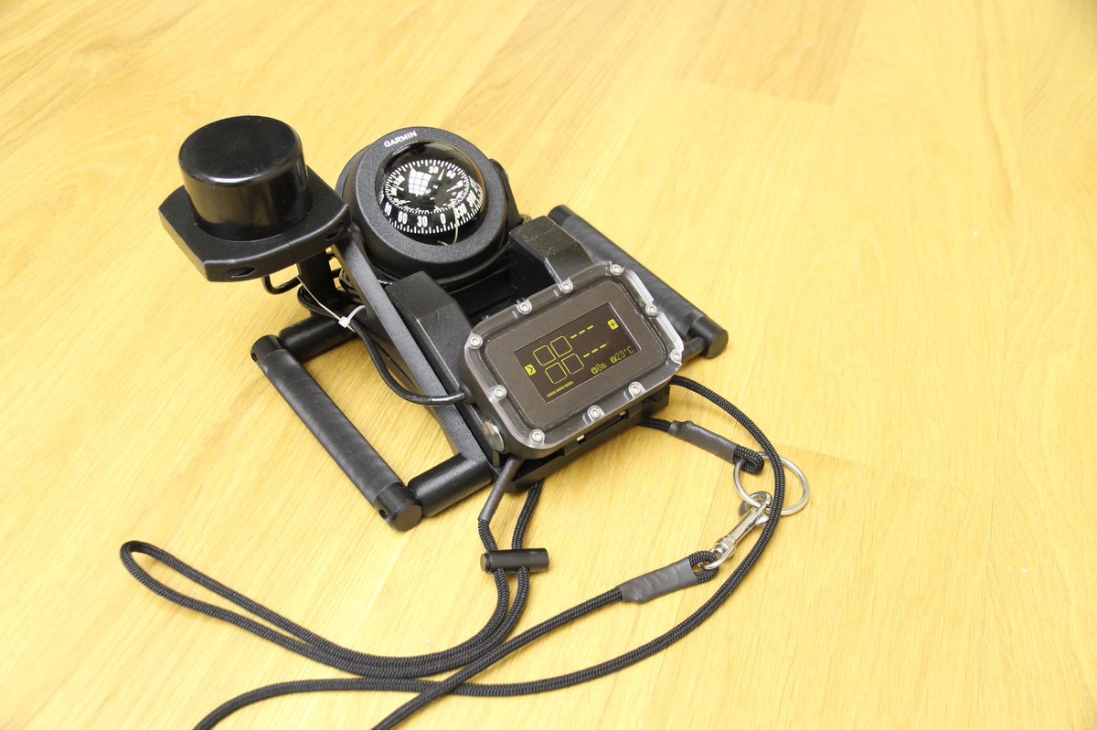
And here is what the first version of the navigation receiver looked like:
It didn’t work very well - there were problems with the reliability of reception (a small antenna installed on the device itself), as a result version 2 appeared rather quickly, which is shown in the first picture.
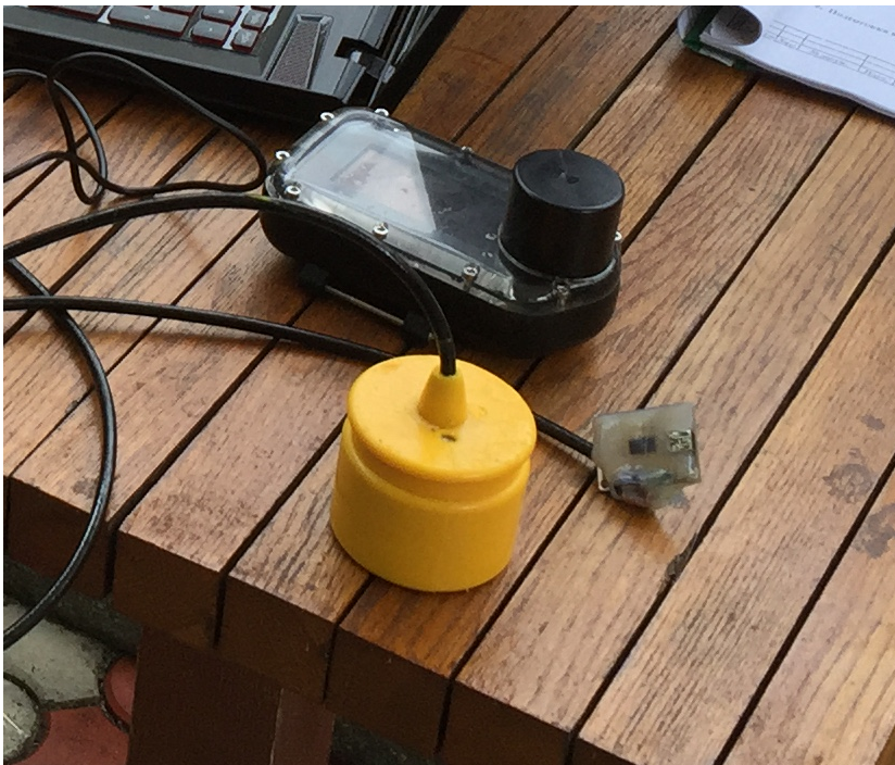
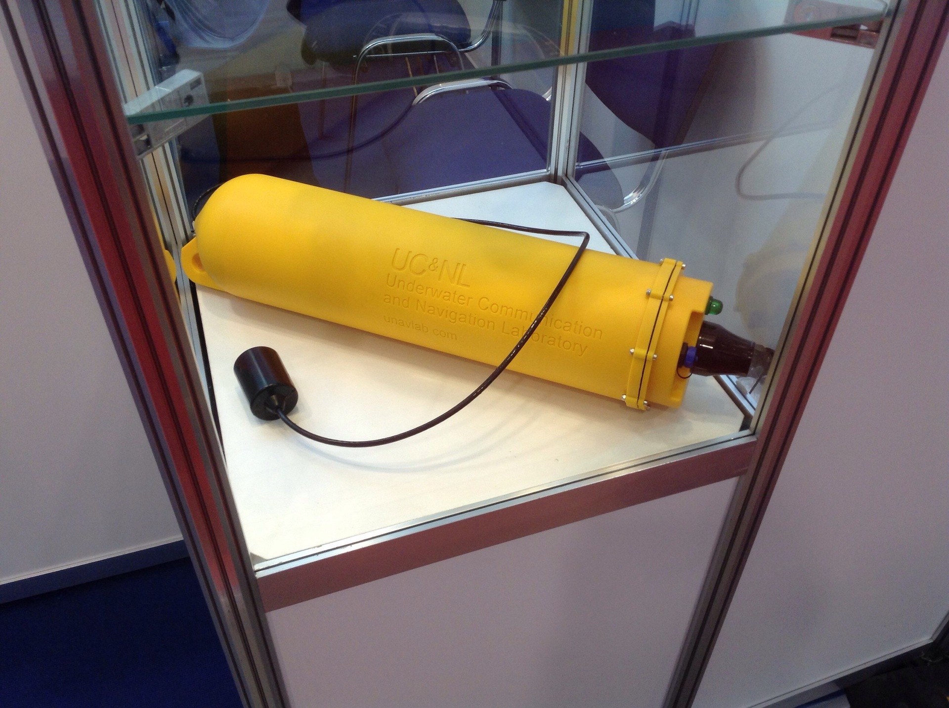
Initially, there were two different solutions: for robots (TNLA / AUV) and for humans. Option for the robot is a cylinder on the cable, filled in polyurethane. All navigator electronics are located inside the receiving antenna; we received our first patent for this layout solution. And just everything was in order with him - this option worked as planned. Here it is, yellow, in the photo:
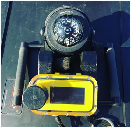
With the diving option, there were always problems - less sensitivity, big mistakes, loss of reception. We conducted a bunch of checks, simulations, experiments, and came to the conclusion that to a greater extent this situation is affected by the location - the small piezo ring of the diving receiver (the black cylinder on the navigator body) is often obscured by the diver.
In the end, they made the decision to cross two devices - the robot navigator takes over, since he is so good at it. We take this receiver either to the balloon (to the diver’s back), or to the shoulder, or we fasten it on the diving panel. From the old navigator there remains only a “display” - the interface part in the form of a separate unit that can be mounted, either on the panel or on the arm. According to the results of real operation, the interface was rewritten - the extra details were removed, the important parameters were made larger.
This is how it looks in the hands of a real diver:
Navigation buoys
Now let's talk about the navigation buoys that provide all this underwater beauty. As mentioned above, the navigation buoy is a piece that receives a GNSS signal and retransmits it to the water.
The first version of the buoys looked like this:
The practice of use has revealed a number of annoying flaws, the most unpleasant of which was associated with the frequent “leakage” of the buoy.
Wicking is interrupted testing and work, dissatisfied users, that's all.
It quickly turned out that the buoys banal flowed through the Chinese GNSS antennas (such an "flasher" on the lid). The antenna was screwed into the lid of the buoy, but it did not flow through the seats (we did not spare the sealant and rubber), but through our own case. Spitting on everything, they decided to make their antenna and hide it under the cover of the buoy, eliminating excess leakage from the structure. The figure below is just a new set of buoys in their own, specially made case for them:
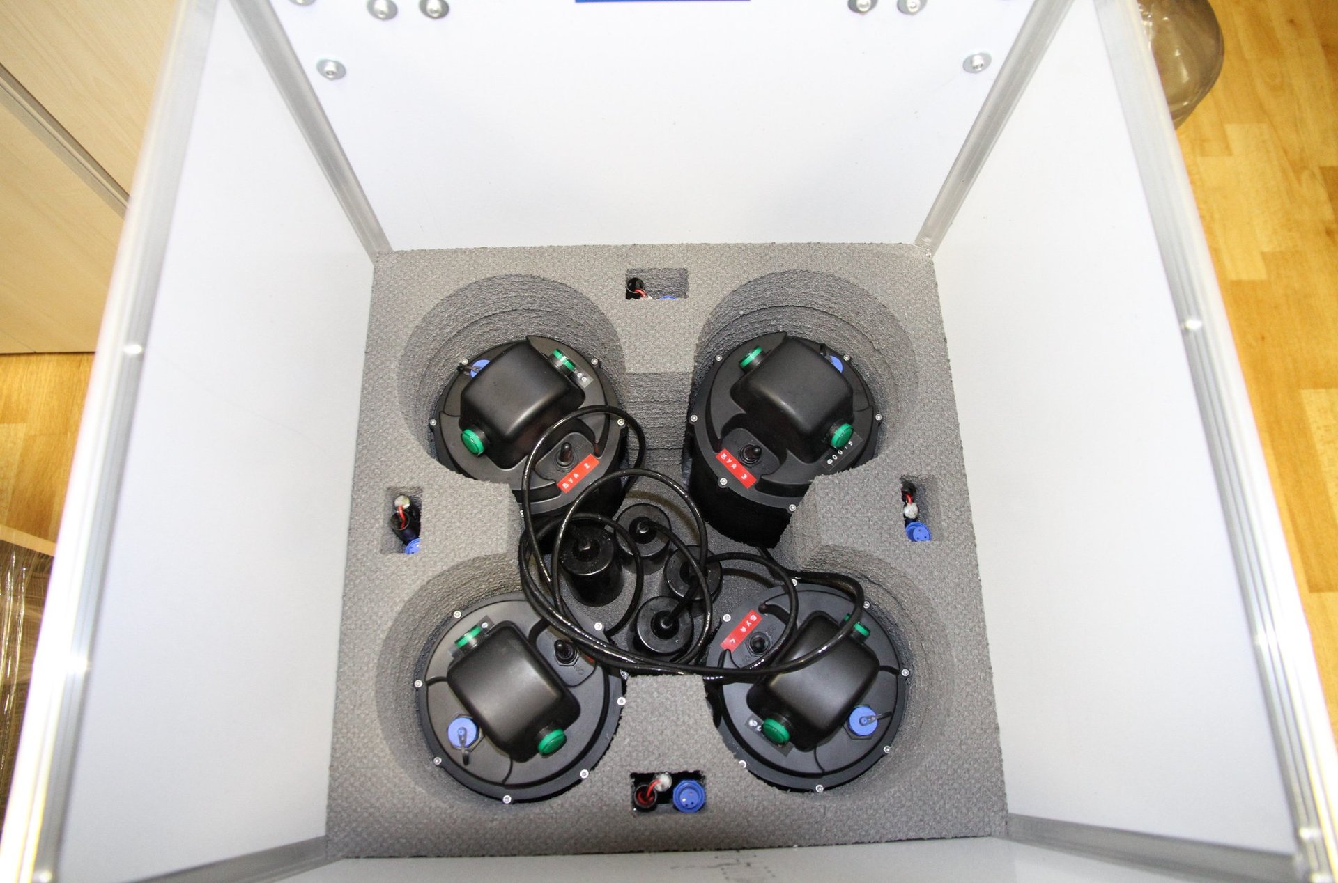
This is the bulge on the lid - the GNSS receiver now lives there. A second light bulb was added to the heap and placed both of them in such a way that they shone almost in a horizontal plane — the previous arrangement was not very well seen from the water.
But the most important changes concerned the internal software. I will show the whole evolution of the quality of navigation data in the series of the following figures.
Here are the results of one of the first serious tests on the White Sea in 2015. Buoys and static receiver, the present White Sea, difficult conditions - shallow water and strong multipath:
Another screenshot from our technology software. The same White Sea. We go on the oars, lowering the receiver on the cable.

But in April 2016, the Volgograd reservoir. The track is unloaded from the diving receiver, then the first version. The average bounce (track width) is about 1.5-2 meters:

From the very beginning we have an open protocol for pairing and unloading the track into KML, GPX and CSV. Diving devices have wireless charging and interface with a PC via Bluetooth. After unloading the track can be imported into GoogleEarth or SAS.Planet. Subsequently, we made a GNSS receiver emulation, so that now the navigation receiver of the robot (it is called RedNODE here) connect directly to the PC cSAS.Planet and use all its facilities — offline maps, the ability to select any substrate, draw a track in real time, and so on. .P.
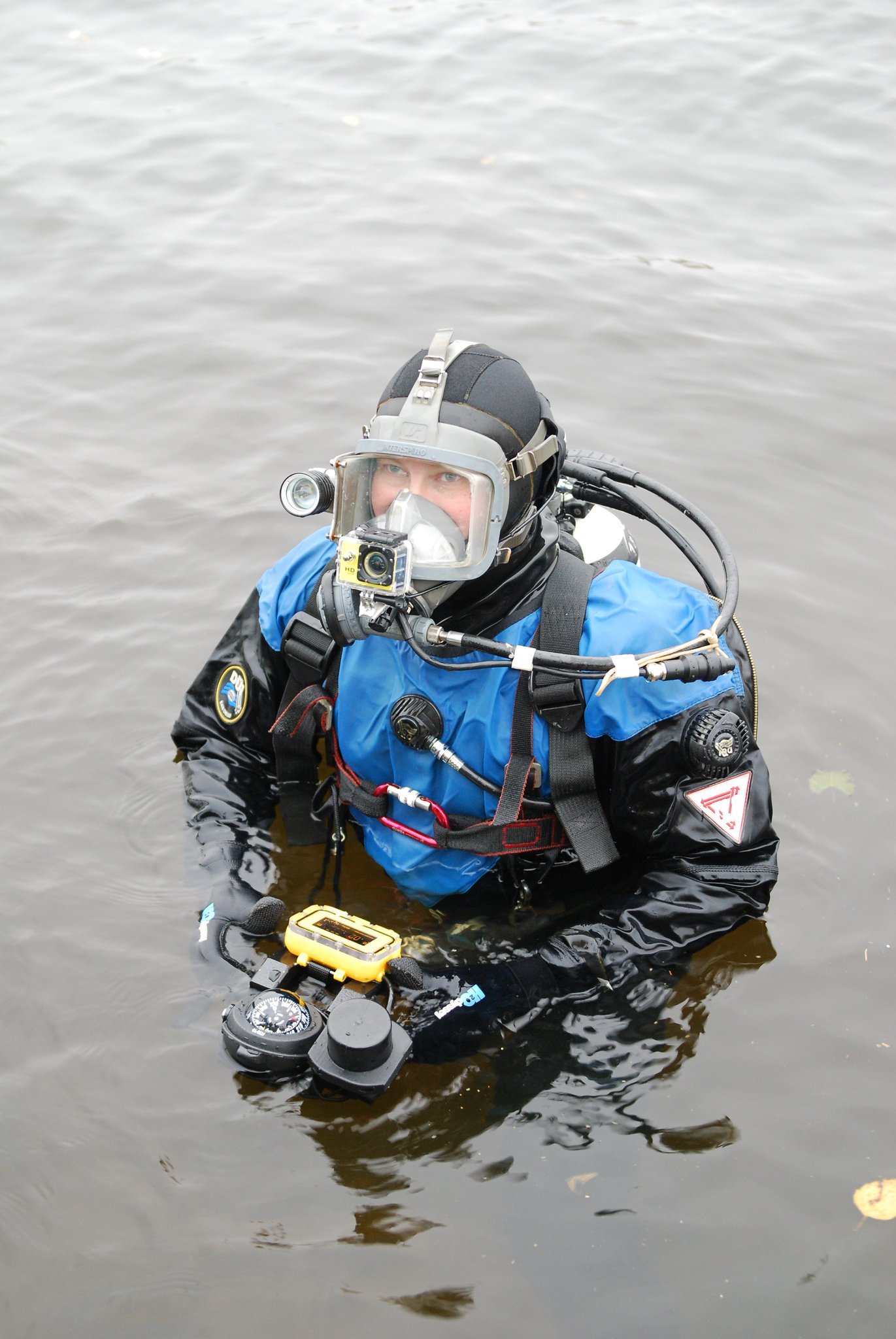
But the diver who helped us in April 2016 at the Volgograd reservoir:
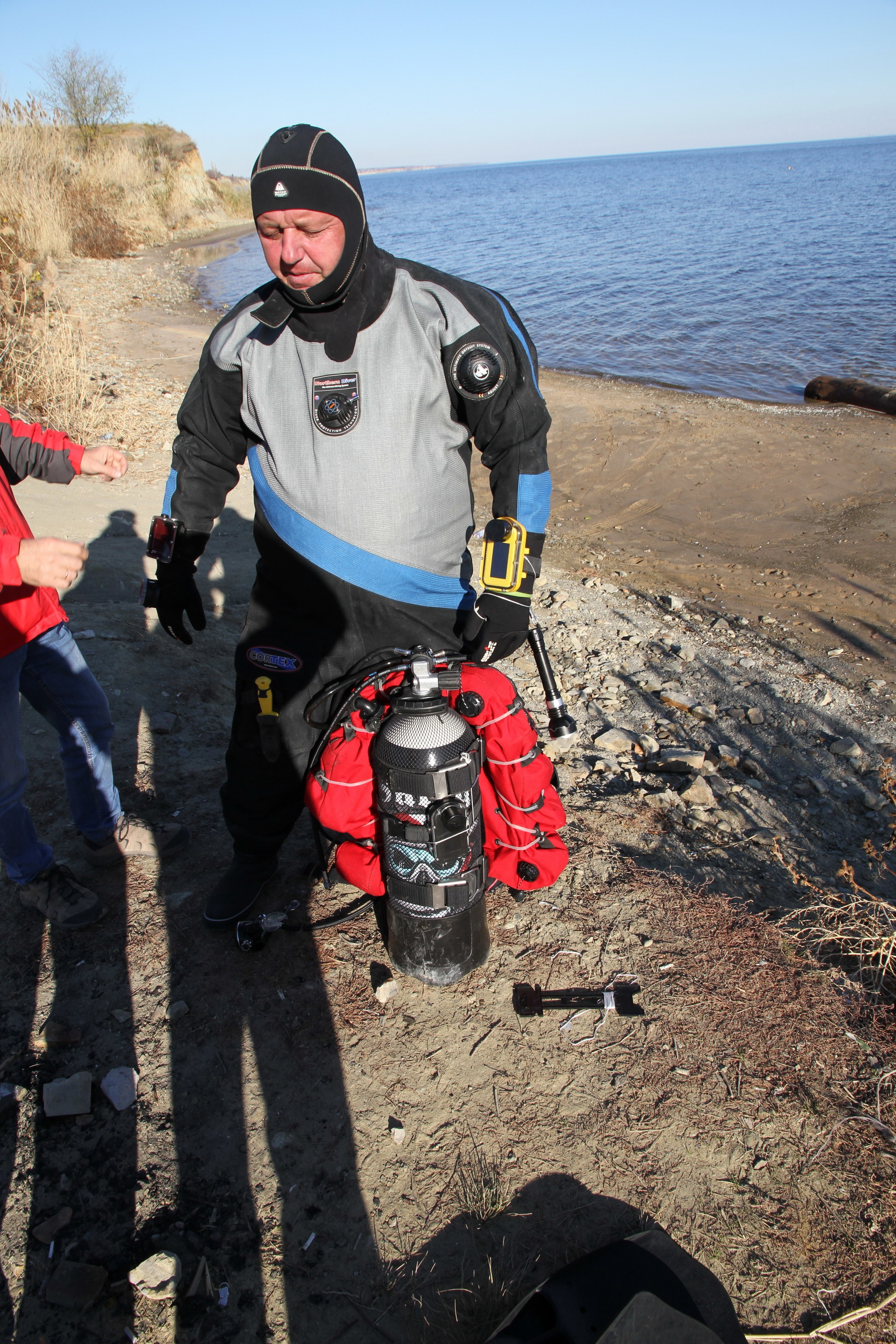
Pay attention, the navigator (yellow) is fixed on his hand, and the second (black) is hanging on the balloon. The track from the reservoir shown above was unloaded from the black navigator that was installed on the cylinder. The track from the wrist navigator turned out to be very bad, with a lot of gaps. It was after this dive, we finally decided to make an acoustic receiver so that it was not shielded by the diver.
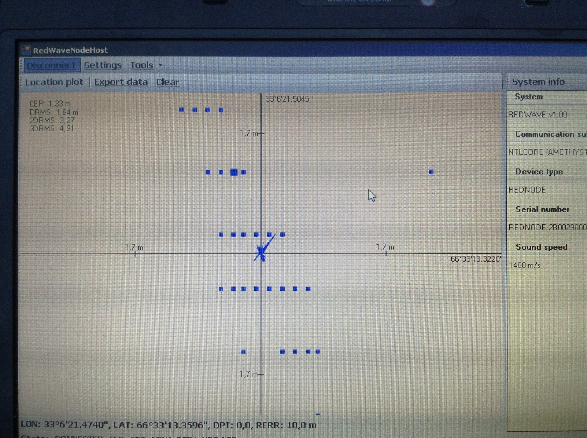
October 2016, the mouth of the river Pichuga, Volgograd reservoir. Simultaneous recording of a track from two RedNODE devices (robot navigator) and RedNAV (diver navigator).
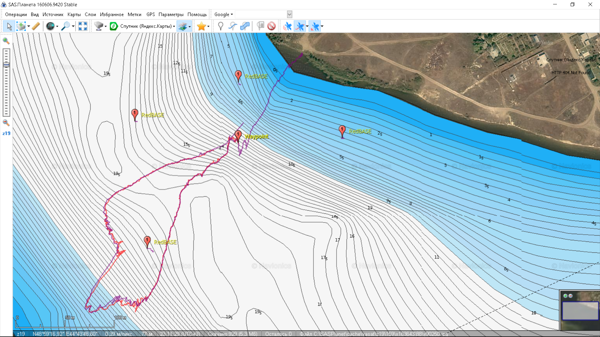
We see two tracks recorded from one boat with the help of two devices - RedNODE (robot navigator) and RedNAV (diver navigator; both were lowered on a rope from a rubber boat). The operation of devices outside the navigation base (outside the buoy shape) was tested. The track RedNODE (purple) was written directly with the help of SAS.Planet, the track of the diving receiver was unloaded post-factum and superimposed. At the “Waypoint 1” point, the diving receiver was pulled out of the water, and the RedNODEs were kept in the water all the way to the shore, as evidenced by the track itself. And even have a photo:

(Picture “Walking a crucian”. Oil, canvas. Pichuga R., October 2016)
At that moment, we were very surprised that the device was working near the coast - these are extremely difficult hydrological conditions, plus everything — work outside the navigation base.
And here are the results obtained on the latest (to date) version of the firmware and hardware. Track movement diver, November 2016, channel them. Moscow in the area of art. Metro "Water Stadium" (Moscow):

I want to draw attention to how much easier the work of a diver. The diver was assigned the following task: to dive, to go to one of the buoys, to go from him to another buoy and to go back - using the navigator.
Immersion conditions - muddy water, visibility no more than 1 meter. The diver walked right along his own trail - the maximum deviation from his own trajectory was no more than 1.5 meters! The distance between buoys 2 and 4 is about 210 meters. That is, the person did not waste time and energy on the search - he just went where the device pointed him.
PS Who and what did:
- One person designed and spread all the boards and drew all the mechanics, plus he thought through the assembly technology, he soldered everything himself (for reference, in one navigator - more than nine hundred soldering points!) And assembled;
- Another person came up with a model and wrote all the firmware (and also helped to collect);
- One more person led all this, simultaneously directing the research and the wheel that was coming to a standstill in search of places and people for tests, and also toured with a demonstration kit and beat thresholds of various funds.
Pps
That which is conceivable is feasible. (C) Mao
Source: https://habr.com/ru/post/370083/
All Articles