HDMI-LVDS. From layout to release
Good day! I would like to bring to your attention a project for a hardware converter HDMI ‑ LVDS built on Texas Instruments ICs. The article has been modified and supplemented.
Formulation of the problem
Develop an HDMI ‑ LVDS converter with no firmware. Hardware implementation on the available element base. The converter should be universal, supporting various types of matrices (with single- and two-channel LVDS) and voltage control signals of inverters. Work in the industrial temperature range.
')
Formulated basic technical requirements:
- two LVDS channels (with the ability to switch and use one);
- The circuitry of the board should include a feeder for the matrix backlight inverter (preferably universal for 12 / 24V arrays);
- two-pixel operation mode of the converter;
- 24-bit matrix support;
- working voltage converter 12 / 24V;
- working voltage of the panel is 3.3V, 5V, 12V (24V from a separate power supply);
- brightness control / backlight on: 3.3V and 5V;
- to be able to control the image of the matrix (to mirror, switch the bit depth, etc.);
Constructive requirements:
- simple (mechanical) configuration of the board (DIP-switches);
- the geometric dimensions of the board are not critical;
- on / off, brightness adjustment buttons on the board;
- on / off indication.
Finding a solution
First option. Texas Instruments offers HDMI-RGB and RGB-LVDS converters in its product line. The TFP401A, SN75LVDS83B and DS90C387A chips. The difference between SN75LVDS83B and DS90C387A is mainly in the fact that the latter has two LVDS channels. The structural diagram is as follows (taken from the TI documentation):

The second option is the use of FPGA chips (programmable logic integrated circuit). The downside of such a system is the addition of software to implement the conversion, which, in turn, provides several advantages, such as setting up a menu for customization, the ability to change the size of a picture, etc.
There is also a third option - the use of specialized controllers. It also draws software based on OS, although it has many advantages, including adjusting the color / brightness of the picture, adjusting indents and the size of the picture, the presence of a menu, etc.
After some analytical work, the odds were on the side of the first solution, based on TI microcircuits. This assembly makes it possible to implement the converter under the necessary requirements.
The choice of the element base for the implementation of power
To power the board with a voltage of 24V, a TI LM24670 converter (24V -> 12V) was chosen.
3.3V and 5V voltages were obtained using ON Semiconductor's NCP3170 converters, and the use of ST1S10PHR STMicroelectronics converters was also worked out, but after studying the characteristics of both microcircuits in price-performance ratio, the former were more affordable.
Control of the backlight and panel settings
Turning on the panel backlight and adjusting the brightness is carried out at 3.3V and 5V (depending on the specific model of the matrix). Inclusion occurs by the means of supplying a logical unit to a certain pin of the inverter, adjustment - using PWM. For control, buttons on the board are brought out (there is also a connector for connecting an external keyboard).
Button handler and PWM are implemented on the STM32F100 controller, which also controls the LED indication (on / off / EDID firmware). It is worth noting that there are two types of backlight control (PWM): logical unit maximum brightness or logical zero maximum brightness. In this design, this is implemented by means of the controller firmware, but it was possible to make a DIP switch. A pin 3.3V / 5V / GND was inserted into the LVDS connector on the board (via a DIP switch). On the matrices there are often control pins: MAP (data card), BIT (bit selection), MODE (normal and mirror mode), etc ... If you need to control these parameters, you can insert the corresponding pin of the matrix into the LVDS converter connector and change one of them.
Setup and first start
Converter configuration is as follows:
1. Controller firmware. For this, the SWD connector was removed, since the plans did not include the manufacture of a 100k batch.
2. Set EDID parameters. It took a long time to deal with the fields and versions of EDID.
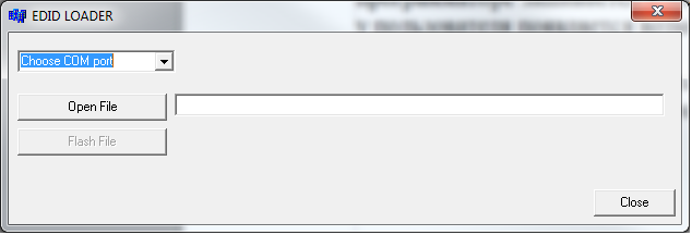
In short, the Deltacast E-EDID Editor is a freeware application. The easiest way is to “merge” the EDID from any monitor, and then edit it for a specific set of matrices and check on the device.

Application "Deltacast E-EDID Editor"
All the basic parameters are in the datasheet on the matrix. The EDID on the programmer is stitched into the eeprom chip (for example, M24C02). When connected to a PC, the eeprom data is read and the user can select the resolution, frequency, etc. parameters.
3. Connection and testing. With some reservations, the first layout was launched and the firmware of the controller and eeprom was debugged.
As a result, three iterations of the board were made (including the release). Several options for printed circuit boards (1 and 2 - single-channel LVDS, 3 - dual-channel LVDS):
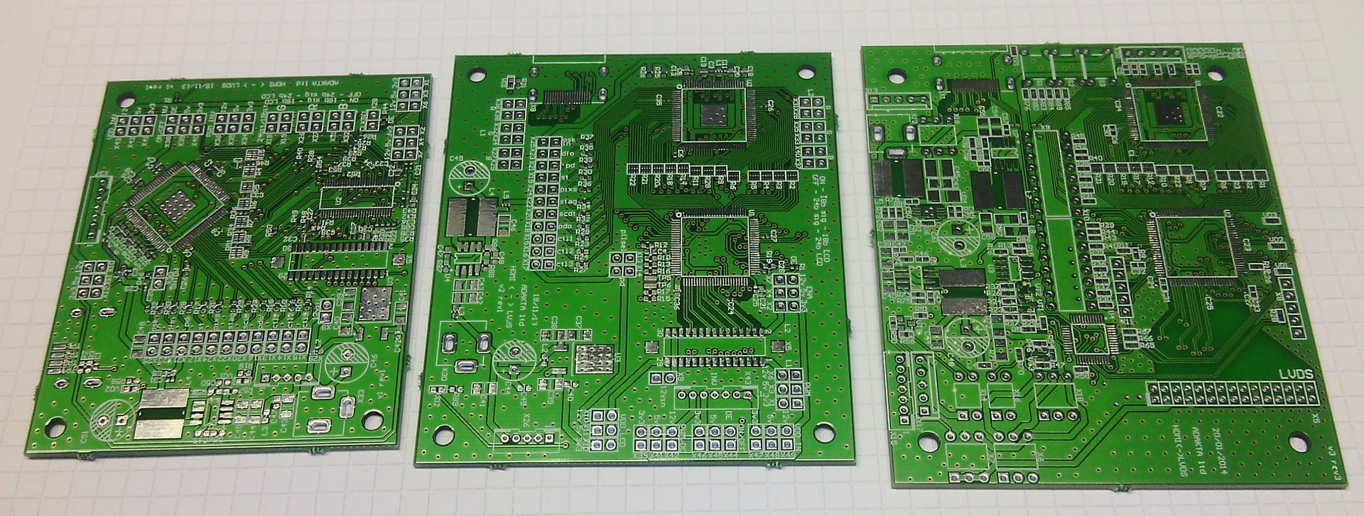
PCB layouts with production
Release
In the release version of the board, it was decided to flash the EDID into the board using a controller. Was written a simple software for the PC. The converter connects to the PC via UART using the USB-UART adapter.
Appendix «EDID LOADER»
A release CD was made about 100 boards. All work, a picture of excellent quality, adjustment and control of the matrix without complaints. A generic EDID configured for most customer matrices has been configured.

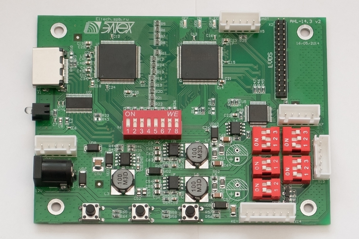
Converter photo
Photo release version of the converter
Development benefits
- hardware implementation of the converter;
- double layer PCB;
- universality;
- easy to set up.
Thanks for attention!
UPD: At the request of the spread BOM and the location of components on the board, as well as firmware.
www.dropbox.com/s/4to153cor6op6su/HDMI-LVDS.zip?dl=0
www.dropbox.com/s/omrao2cv4vbp6hd/AHL-14.2.zip?dl=0
Source: https://habr.com/ru/post/370073/
All Articles