Scientific and technical myths, part 1. Why do airplanes fly?
In the modern world, many people are interested in science and technology and are trying, at least in general terms, to understand how the things that surround them work. Thanks to this desire for enlightenment, there is scientific literature and websites like Giktaims. And since it is difficult for most people to read and perceive series of formulas, theories presented in such publications inevitably undergo a significant simplification in an attempt to convey to the reader the "essence" of the idea with a simple and understandable explanation that is easy to perceive and remember. Unfortunately, some of these “simple explanations” are fundamentally incorrect , but they turn out to be so “obvious” that, without being subjected to special doubts, they begin to migrate from one publication to another and often become the dominant point of view, despite its fallacy.
As one example, try to answer the simple question: “where does the lift force in the plane's wing come from?”
')
If your explanation includes “different lengths of the upper and lower surfaces of the wing”, “different air flow rates at the upper and lower edges of the wings” and “Bernoulli's law”, then I have to inform you that you are most likely to become a victim of the most popular myth taught sometimes even in the school curriculum.
Let's start by recalling what is at stake
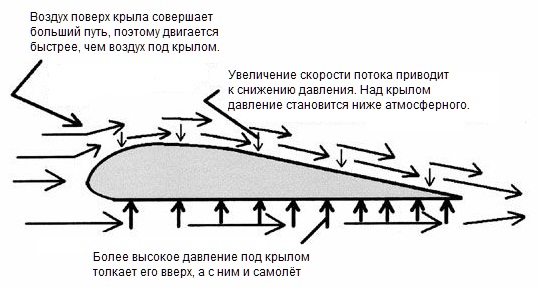
The explanation of the lifting force of the wing in the framework of the myth is as follows:
And to demonstrate this idea, a simple flexible and light sheet of paper is enough. We take a sheet, bring it to the mouth, and blow it over it to create a model in which the air flow above the sheet of paper moves faster than under it. And voila - from the first or second attempt a sheet of paper defying the agony really rises under the effect of lifting force upwards. The theorem is proved!
... or not? ..
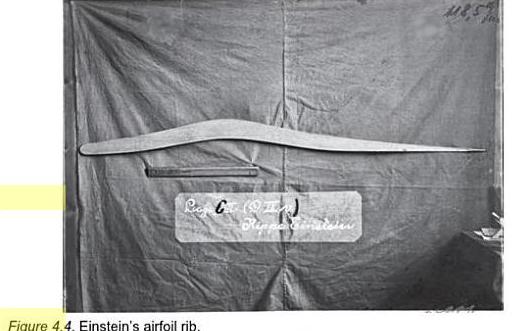
There is a story (I really don’t know how true it is) that one of the first people who suggested this theory was none other than Albert Einstein himself. According to this story in 1916, he wrote a relevant article and based on it proposed his own version of the “ideal wing”, which, in his opinion, maximized the speed difference above and below the wing, and in profile it looked like this:
In the wind tunnel, a full-fledged model of the wing with this profile was blown through, but alas, its aerodynamic qualities turned out to be extremely poor. In contrast - paradoxically! - from many wings with a perfectly symmetrical profile, in which the air path above the wing and under it should have been fundamentally the same. There was clearly something wrong with Einstein’s reasoning. And probably the most obvious manifestation of this irregularity was that some pilots began to fly upside down on their planes as an acrobatic stunt. The first aircraft that tried to roll over in flight had problems with fuel and oil that did not flow where they needed and flowed where it was not needed, but after the aerobatics enthusiasts had created fuel in the 30s of the last century and oil systems that can work for a long time in an inverted position, flying upside down has become a common sight at an air show. In 1933, for example, one American flew upside down from San Diego to Los Angeles. In some magical way, the inverted wing still generated upward lifting force.
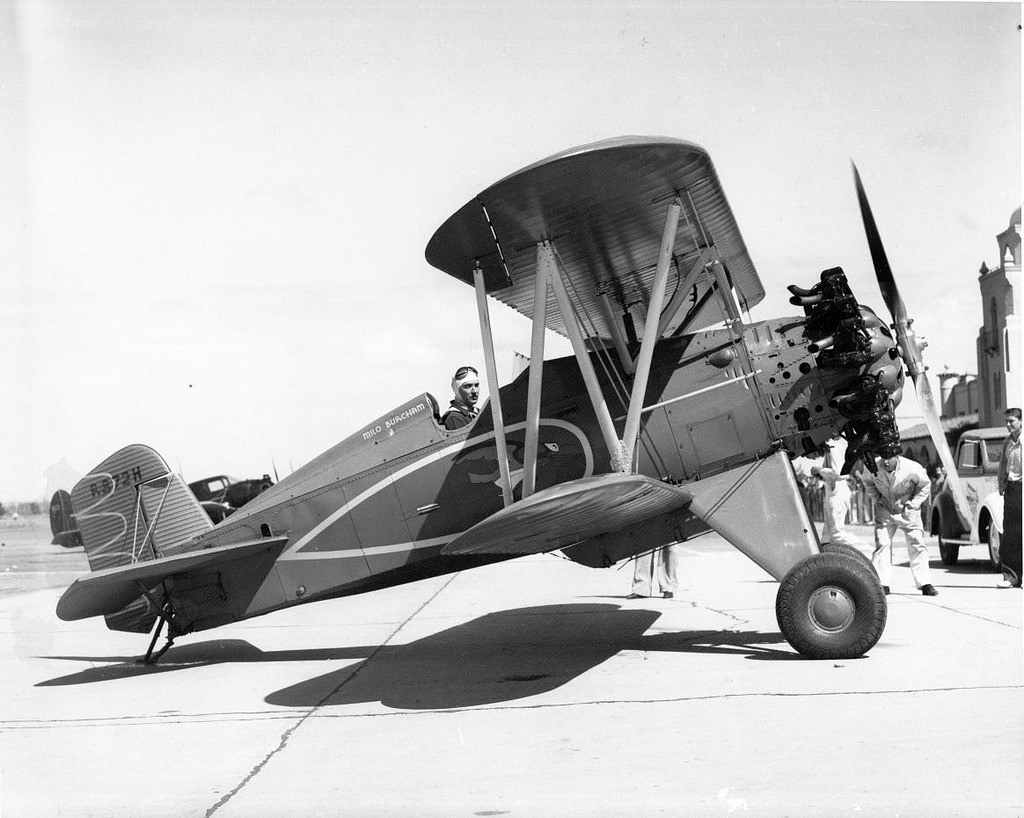
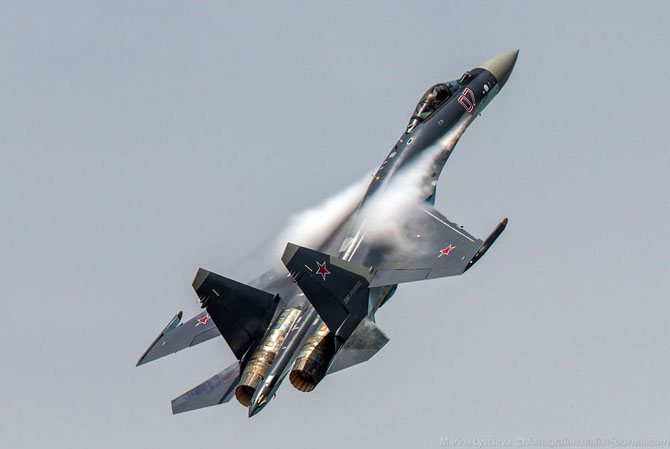
Look at this picture - it shows a plane similar to the one on which the flight record was set upside down. Pay attention to the usual wing profile (Boeing-106B airfoil), which, according to the above reasoning, should create lift from the bottom to the top surface.
So, our simple wing lift model has some difficulties that can generally be reduced to two simple observations:
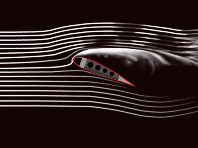
What is the cause of the error? It turns out that in the argument given at the beginning of the article, the number 4 is completely wrong (and generally speaking, it is simply taken from the ceiling). Visualization of the flow of air around the wing in a wind tunnel shows that the flow front, divided into two parts by the wing, does not close at all behind the edge of the wing.
Simply put, the air “does not know” that it needs to move at a certain speed around the wing in order to fulfill some condition that seems obvious to us. And although the flow velocity above the wing is indeed higher than under it, this is not the cause of the formation of lift, but the fact that there is a region of reduced pressure above the wing, but a region of elevated pressure under the wing. Getting from the area of normal pressure to the rarefied area, the air is accelerated by the differential pressure, and getting into the area with increased pressure is decelerated. An important particular example of such “non-Bernoulli’s” behavior is vividly demonstrated by ekranoplans: when the wing approaches the ground, its lifting force increases (the elevated pressure area is compressed by the ground), whereas, as part of the “Bernoule’s” reasoning, the wing together with the ground form a kind of narrowing tunnel that in the framework of naive reasoning, it would be necessary to accelerate the air and, due to this, to drag the wing to the ground, just as it is done in similar reasoning about the “mutual attraction of steamers "sah. Moreover, in the case of an ekranoplan, the situation is even worse in many ways, since one of the “walls” of this tunnel moves at high speed towards the wing, additionally “dispersing” the air and contributing to a further reduction in lift. However, the actual practice of the “screen effect” demonstrates the opposite trend, clearly demonstrating the danger of the logic of reasoning about the lifting force built on naive attempts to guess the air flow velocity field around the wing.
Strange as it may seem, another incorrect theory of lift, rejected in the 19th century, gives a much more approximate explanation to the truth. Sir Isaac Newton suggested that the interaction of an object with an incoming air flow can be modeled by assuming that the incoming flow consists of tiny particles hitting the object and bouncing off of it. With an oblique arrangement of the object relative to the incident flow, the particles will mainly be reflected by the object downwards and, by virtue of the law of conservation of momentum, each time the particle deflects down the object will receive an upward momentum. An ideal wing in a similar model would be a flat kite inclined to the incident flow:
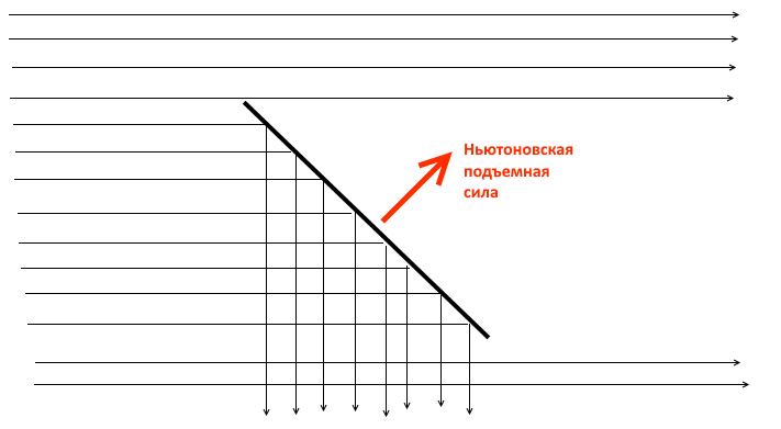
The lifting force in this model arises due to the fact that the wing directs a part of the air flow downwards, this redirection requires the application of a certain force to the air flow, and the lifting force is the corresponding resistance force from the air flow to the wing. And although the initial “shock” model is generally not correct, this explanation is indeed true in such a generalized formulation. Any wing works due to the fact that it deflects a part of the incoming air flow downwards and this, in particular, explains why the lift force of the wing is proportional to the density of the air flow and the square of its speed. This gives us a first approximation to the correct answer: the wing creates lift because the air flow lines after the passage of the wing are on average directed downwards . And the more we divert the flow down (for example, by increasing the angle of attack), the more lift will be.
A bit of an unexpected result, right? However, it still does not bring us closer to understanding why the air, after passing through the wing, turns out to be moving down. The fact that the Newtonian shock model is incorrect is shown experimentally by experiments that demonstrated that the real resistance of the flow is lower than the Newtonian model predicts, and the generated lifting force is higher. The reason for these discrepancies is that in the Newton model the air particles do not interact with each other, whereas the real current lines cannot cross each other, as this is shown in the figure above. The conditional “air particles” “bounce” under the wing collide with others and begin to “push” them away from the wing even before they collide with it, and the air current particles that are above the wing “pry” the air particles below, in the empty space left behind the wing:
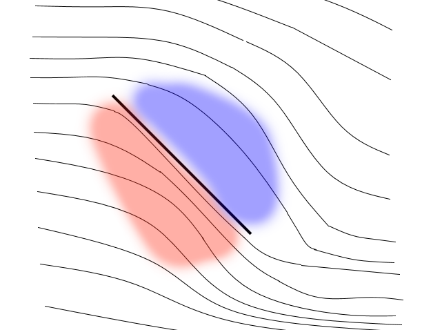
In other words, the interaction of the “bounced off” and “oncoming” flows creates a high pressure area (red) under the wing, and the “shadow” punched by the wing in the flow forms a low pressure area (blue). The first region deflects the flow under the wing down even before this flow touches its surface, and the second causes the flow above the wing to bend down, although it did not touch the wing at all. The combined pressure of these areas along the contour of the wing, in fact, forms as a result a lifting force. At the same time, an interesting point is that inevitably the high pressure area of a properly designed wing arises in front of the wing in contact with its surface only over a small area in the leading edge of the wing, while the high pressure area under the wing and the low pressure area above it contact the wing on significantly large area. As a result, the lift force of a wing formed by two areas around the upper and lower surfaces of the wing can be much greater than the air resistance force that the high-pressure area located in front of the front edge of the wing provides.

Since the presence of areas of different pressure bends the air flow lines, it is often convenient to determine these areas precisely by this bend. For example, if the current lines above the wing “bend down”, then in this area there is a pressure gradient from top to bottom. And if at a sufficiently large distance above the wing the pressure is atmospheric, then as it approaches the wing from top to bottom, the pressure should fall and directly above the wing it will be below atmospheric. Having considered a similar “curvature down”, but already under the wing, we get that if we start from a low enough point under the wing, then approaching the wing from bottom to top, we will come to a pressure area that is higher than atmospheric. Similarly, the "pushing" of the streamlines in front of the front edge of the wing corresponds to the existence of an elevated pressure area in front of this edge. Within the framework of such logic, it can be said that the wing creates lift by bending the air flow lines around the wing . Since the air flow lines “stick” to the wing surface (the Coanda effect) and to each other, by changing the wing profile, we force the air to move around it along a curved trajectory and thereby form the pressure gradient we need. For example, to ensure a flight upside down, it is enough to create the desired angle of attack by directing the nose of the aircraft away from the ground:
Again, a little unexpected, right? Nevertheless, this explanation is closer to the truth than the original version of "the air accelerates over the wing, because it needs to go a longer distance over the wing than under it." In addition, in its terms it is easiest to understand the phenomenon, which is called “flow disruption” or “aircraft stalling”. In a normal situation, increasing the angle of attack of the wing, we thereby increase the curvature of the air flow and, accordingly, the lifting force. The price for this is an increase in aerodynamic drag, since the low pressure region gradually shifts from the position “above the wing” to the position “slightly behind the wing” and accordingly begins to slow down the plane. However, after a certain limit, the situation suddenly changes dramatically. The blue line on the graph is the lift coefficient, the red is the drag coefficient, the horizontal axis corresponds to the angle of attack.

The fact is that the “stickiness” of the flow to the streamlined surface is limited, and if we try to distort the air flow too much, it will begin to “tear off” from the surface of the wing. The low pressure region formed behind the wing begins to “suck in” not the air flow coming from the leading edge of the wing, but the air from the region remaining behind the wing, and the lifting force generated by the upper part of the wing completely or partially (depending on where the separation occurred) disappears, and frontal resistance will increase.
For an ordinary plane, stalling is an extremely unpleasant situation. The wing lifting force decreases with decreasing aircraft speed or decreasing air density, and besides, turning the aircraft requires more lift than just horizontal flight. In normal flight, all these factors are compensated for precisely by choosing the angle of attack. The slower the plane flies, the less dense the air (the plane climbed to a greater height or sets in hot weather) and the steeper the turn, the more you have to make this angle. And if an unwary pilot crosses a certain line, then the lifting force rests on the "ceiling" and becomes insufficient to keep the aircraft in the air. Adds problems and increased air resistance, which leads to a loss of speed and a further reduction in lift. As a result, the plane begins to fall - "falls." Along the way, there may be problems with control due to the fact that the lifting force is redistributed along the wing and begins to try to "turn" the plane or the control surfaces are in the area of the flow that has been torn off and cease to generate sufficient control force. And in a sharp turn, for example, the flow can only be disrupted from one wing, as a result of which the plane will start not only to lose height, but also to rotate - it will go into a tailspin. The combination of these factors remains one of the frequent causes of air crashes. On the other hand, some modern combat aircraft are specially designed in such a special way as to maintain controllability in such supercritical attack modes. This allows such fighters to brake sharply in the air if necessary. Sometimes it is used for braking in straight flight, but more often it is demanded in turns, because the lower the speed, the smaller, all other things being equal, the turning radius of the aircraft. And yes, you guessed it - it is this very “super-maneuverability” that specialists who have designed the aerodynamics of domestic fighters of 4 and 5 generations are justly proud of.
However, we still have not answered the main question: where, in fact, are areas of high and low pressure around the wing in the oncoming air flow? After all, both phenomena (“sticking of the flow to the wing” and “air moves faster over the wing”), which can explain flight, are the result of a certain distribution of pressures around the wing, and not its cause. But why such a pattern of pressure is formed, and not some other one?

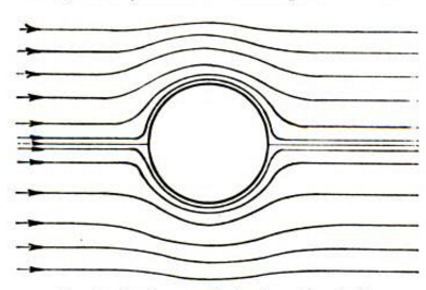
Unfortunately, the answer to this question inevitably requires the involvement of mathematics. Let's imagine that our wing is infinitely long and the same along the entire length, so that the movement of air around it can be modeled in a two-dimensional cut. And let's assume, for a start, that our wing is a role ... an infinitely long cylinder in a stream of ideal fluid. By virtue of the infinity of the cylinder, such a problem can be reduced to considering the flow around a circle in the plane by the flow of an ideal fluid. For such a trivial and idealized case, there is an exact analytical solution that predicts that with a stationary cylinder, the total effect of the fluid on the cylinder will be zero.
And now let's consider some kind of tricky transformation of the plane into itself, which mathematicians call the conformal mapping. It turns out that one can choose a transformation that, on the one hand, preserves the equations of motion of the fluid flow, and on the other hand, it transforms a circle into a shape that has a wing-like profile. Then the fluid lines for the cylinder transformed by the same transformation become the solution for the flow of fluid around our improvised wing.
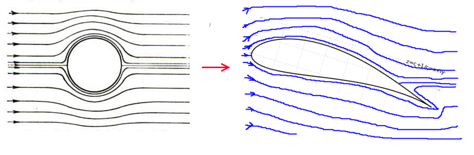
Our original circle in the flow of an ideal fluid has two points in which the streamlines touch the surface of the circle, and therefore the same two points will exist on the profile surface after applying the transformation to the cylinder. And depending on the rotation of the flow relative to the initial cylinder (“angle of attack”), they will be located in different places on the surface of the formed “wing”. And it will almost always mean that part of the fluid flow lines around the profile will have to bend around the rear, sharp edge of the wing, as shown in the picture above.
This is potentially a perfect fluid. But not for real.
The presence of even a small amount of friction (viscosity) in a real liquid or gas causes the flow similar to that shown in the picture to be immediately disturbed - the upper flow will shift the point where the streamline contacts the wing surface until it is strictly on the rear edge of the wing. (the postulate of Zhukovsky-Chaplygin, it is Kutta’s aerodynamic condition). And if you convert the "wing" back into a "cylinder", then the shifted current lines will be approximately like this:
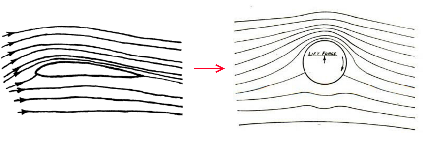
But if the viscosity of a liquid (or gas) is very low, then the solution obtained in a similar way should also be suitable for a cylinder. And it turns out that such a solution can indeed be found if it is assumed that the cylinder rotates . That is, the physical constraints associated with the flow of fluid around the trailing edge of the wing lead to the fact that the movement of fluid from all possible solutions will tend to come to one particular solution in which part of the fluid flow rotates around the equivalent cylinder, breaking away from it at a strictly defined point . And since the rotating cylinder in the flow of fluid creates a lifting force, it creates the corresponding wing. The component of the flow movement corresponding to this “rotational speed of the cylinder” is called the flow circulation around the wing, and Zhukovsky's theorem says that a similar characteristic can be generalized for an arbitrary wing, and allows you to quantitatively calculate the lifting force of the wing on its basis. In the framework of this theory, the lifting force of the wing is ensured by the circulation of air around the wing, which is generated and maintained at the moving wing by the above-indicated friction forces, which exclude the flow of air around its sharp rear edge.
Amazing result, isn't it?
The theory described is of course strongly idealized (an infinitely long homogeneous wing, an ideal homogeneous incompressible gas / liquid flow without friction around the wing), but gives a fairly accurate approximation for real wings and ordinary air. Just do not take in her part of the circulation as evidence that the air really rotates around the wing. Circulation is simply a number, indicating how much the flow at the upper and lower edges of the wing must differ in order for the solution of fluid flow movements to ensure the separation of the streamlines strictly at the trailing edge of the wing. It is also not necessary to take the "principle of the sharp rear edge of the wing" as a necessary condition for the emergence of lifting force: the sequence of reasoning instead sounds like "if the wing has a sharp rear edge, then the lifting force is formed this way".
Let's try to summarize. The interaction of air with the wing forms areas of high and low pressure around the wing, which distort the air flow so that it bends around the wing. The sharp rear edge of the wing leads to the fact that in the ideal flow, of all the potential solutions of the equations of motion, only one concrete is realized, which excludes the flow of air around the sharp trailing edge. This solution depends on the angle of attack and, in the case of a conventional wing, has a region of reduced pressure above the wing and a region of increased pressure under it. The corresponding pressure difference forms the lift force of the wing, forces the air to move faster over the upper edge of the wing and slows down the air below the bottom. Quantitatively, it is convenient to describe the lifting force numerically through this velocity difference above and below the wing in the form of a characteristic, which is called the “circulation” of the flow. In this case, in accordance with the third Newton's law, the lifting force acting on the wing means that the wing deflects down part of the incoming air flow — in order for the aircraft to fly, a part of the surrounding air must continuously move downwards. Relying on this downward-moving air stream, the plane “flies”.
The simple explanation with “air that needs to go a longer way over the wing than under it” is incorrect.
As one example, try to answer the simple question: “where does the lift force in the plane's wing come from?”
')
If your explanation includes “different lengths of the upper and lower surfaces of the wing”, “different air flow rates at the upper and lower edges of the wings” and “Bernoulli's law”, then I have to inform you that you are most likely to become a victim of the most popular myth taught sometimes even in the school curriculum.
Let's start by recalling what is at stake
The explanation of the lifting force of the wing in the framework of the myth is as follows:
- The wing has an asymmetrical profile below and above
- The continuous air flow is divided by the wing into two parts, one of which passes over the wing, and the other below.
- We consider laminar flow in which the air flow is tight to the wing surface.
- Since the profile is asymmetrical, in order to converge behind the wing at one point, the “upper” stream needs to go a longer way than the “lower” one; therefore, the air above the wing has to move with greater speed than under it
- According to the Bernoulli law, the static pressure in the flow decreases with increasing flow velocity, therefore in the flow above the wing the static pressure will be lower
- The pressure difference in the flow under the wing and above it is the lifting force
And to demonstrate this idea, a simple flexible and light sheet of paper is enough. We take a sheet, bring it to the mouth, and blow it over it to create a model in which the air flow above the sheet of paper moves faster than under it. And voila - from the first or second attempt a sheet of paper defying the agony really rises under the effect of lifting force upwards. The theorem is proved!
... or not? ..
There is a story (I really don’t know how true it is) that one of the first people who suggested this theory was none other than Albert Einstein himself. According to this story in 1916, he wrote a relevant article and based on it proposed his own version of the “ideal wing”, which, in his opinion, maximized the speed difference above and below the wing, and in profile it looked like this:
In the wind tunnel, a full-fledged model of the wing with this profile was blown through, but alas, its aerodynamic qualities turned out to be extremely poor. In contrast - paradoxically! - from many wings with a perfectly symmetrical profile, in which the air path above the wing and under it should have been fundamentally the same. There was clearly something wrong with Einstein’s reasoning. And probably the most obvious manifestation of this irregularity was that some pilots began to fly upside down on their planes as an acrobatic stunt. The first aircraft that tried to roll over in flight had problems with fuel and oil that did not flow where they needed and flowed where it was not needed, but after the aerobatics enthusiasts had created fuel in the 30s of the last century and oil systems that can work for a long time in an inverted position, flying upside down has become a common sight at an air show. In 1933, for example, one American flew upside down from San Diego to Los Angeles. In some magical way, the inverted wing still generated upward lifting force.
Look at this picture - it shows a plane similar to the one on which the flight record was set upside down. Pay attention to the usual wing profile (Boeing-106B airfoil), which, according to the above reasoning, should create lift from the bottom to the top surface.
So, our simple wing lift model has some difficulties that can generally be reduced to two simple observations:
- The lift force of the wing depends on its orientation relative to the oncoming air flow - the angle of attack
- Symmetrical profiles (including the banal flat sheet of plywood) also create lift
What is the cause of the error? It turns out that in the argument given at the beginning of the article, the number 4 is completely wrong (and generally speaking, it is simply taken from the ceiling). Visualization of the flow of air around the wing in a wind tunnel shows that the flow front, divided into two parts by the wing, does not close at all behind the edge of the wing.
Simply put, the air “does not know” that it needs to move at a certain speed around the wing in order to fulfill some condition that seems obvious to us. And although the flow velocity above the wing is indeed higher than under it, this is not the cause of the formation of lift, but the fact that there is a region of reduced pressure above the wing, but a region of elevated pressure under the wing. Getting from the area of normal pressure to the rarefied area, the air is accelerated by the differential pressure, and getting into the area with increased pressure is decelerated. An important particular example of such “non-Bernoulli’s” behavior is vividly demonstrated by ekranoplans: when the wing approaches the ground, its lifting force increases (the elevated pressure area is compressed by the ground), whereas, as part of the “Bernoule’s” reasoning, the wing together with the ground form a kind of narrowing tunnel that in the framework of naive reasoning, it would be necessary to accelerate the air and, due to this, to drag the wing to the ground, just as it is done in similar reasoning about the “mutual attraction of steamers "sah. Moreover, in the case of an ekranoplan, the situation is even worse in many ways, since one of the “walls” of this tunnel moves at high speed towards the wing, additionally “dispersing” the air and contributing to a further reduction in lift. However, the actual practice of the “screen effect” demonstrates the opposite trend, clearly demonstrating the danger of the logic of reasoning about the lifting force built on naive attempts to guess the air flow velocity field around the wing.
Strange as it may seem, another incorrect theory of lift, rejected in the 19th century, gives a much more approximate explanation to the truth. Sir Isaac Newton suggested that the interaction of an object with an incoming air flow can be modeled by assuming that the incoming flow consists of tiny particles hitting the object and bouncing off of it. With an oblique arrangement of the object relative to the incident flow, the particles will mainly be reflected by the object downwards and, by virtue of the law of conservation of momentum, each time the particle deflects down the object will receive an upward momentum. An ideal wing in a similar model would be a flat kite inclined to the incident flow:
The lifting force in this model arises due to the fact that the wing directs a part of the air flow downwards, this redirection requires the application of a certain force to the air flow, and the lifting force is the corresponding resistance force from the air flow to the wing. And although the initial “shock” model is generally not correct, this explanation is indeed true in such a generalized formulation. Any wing works due to the fact that it deflects a part of the incoming air flow downwards and this, in particular, explains why the lift force of the wing is proportional to the density of the air flow and the square of its speed. This gives us a first approximation to the correct answer: the wing creates lift because the air flow lines after the passage of the wing are on average directed downwards . And the more we divert the flow down (for example, by increasing the angle of attack), the more lift will be.
A bit of an unexpected result, right? However, it still does not bring us closer to understanding why the air, after passing through the wing, turns out to be moving down. The fact that the Newtonian shock model is incorrect is shown experimentally by experiments that demonstrated that the real resistance of the flow is lower than the Newtonian model predicts, and the generated lifting force is higher. The reason for these discrepancies is that in the Newton model the air particles do not interact with each other, whereas the real current lines cannot cross each other, as this is shown in the figure above. The conditional “air particles” “bounce” under the wing collide with others and begin to “push” them away from the wing even before they collide with it, and the air current particles that are above the wing “pry” the air particles below, in the empty space left behind the wing:
In other words, the interaction of the “bounced off” and “oncoming” flows creates a high pressure area (red) under the wing, and the “shadow” punched by the wing in the flow forms a low pressure area (blue). The first region deflects the flow under the wing down even before this flow touches its surface, and the second causes the flow above the wing to bend down, although it did not touch the wing at all. The combined pressure of these areas along the contour of the wing, in fact, forms as a result a lifting force. At the same time, an interesting point is that inevitably the high pressure area of a properly designed wing arises in front of the wing in contact with its surface only over a small area in the leading edge of the wing, while the high pressure area under the wing and the low pressure area above it contact the wing on significantly large area. As a result, the lift force of a wing formed by two areas around the upper and lower surfaces of the wing can be much greater than the air resistance force that the high-pressure area located in front of the front edge of the wing provides.
Since the presence of areas of different pressure bends the air flow lines, it is often convenient to determine these areas precisely by this bend. For example, if the current lines above the wing “bend down”, then in this area there is a pressure gradient from top to bottom. And if at a sufficiently large distance above the wing the pressure is atmospheric, then as it approaches the wing from top to bottom, the pressure should fall and directly above the wing it will be below atmospheric. Having considered a similar “curvature down”, but already under the wing, we get that if we start from a low enough point under the wing, then approaching the wing from bottom to top, we will come to a pressure area that is higher than atmospheric. Similarly, the "pushing" of the streamlines in front of the front edge of the wing corresponds to the existence of an elevated pressure area in front of this edge. Within the framework of such logic, it can be said that the wing creates lift by bending the air flow lines around the wing . Since the air flow lines “stick” to the wing surface (the Coanda effect) and to each other, by changing the wing profile, we force the air to move around it along a curved trajectory and thereby form the pressure gradient we need. For example, to ensure a flight upside down, it is enough to create the desired angle of attack by directing the nose of the aircraft away from the ground:
Again, a little unexpected, right? Nevertheless, this explanation is closer to the truth than the original version of "the air accelerates over the wing, because it needs to go a longer distance over the wing than under it." In addition, in its terms it is easiest to understand the phenomenon, which is called “flow disruption” or “aircraft stalling”. In a normal situation, increasing the angle of attack of the wing, we thereby increase the curvature of the air flow and, accordingly, the lifting force. The price for this is an increase in aerodynamic drag, since the low pressure region gradually shifts from the position “above the wing” to the position “slightly behind the wing” and accordingly begins to slow down the plane. However, after a certain limit, the situation suddenly changes dramatically. The blue line on the graph is the lift coefficient, the red is the drag coefficient, the horizontal axis corresponds to the angle of attack.
The fact is that the “stickiness” of the flow to the streamlined surface is limited, and if we try to distort the air flow too much, it will begin to “tear off” from the surface of the wing. The low pressure region formed behind the wing begins to “suck in” not the air flow coming from the leading edge of the wing, but the air from the region remaining behind the wing, and the lifting force generated by the upper part of the wing completely or partially (depending on where the separation occurred) disappears, and frontal resistance will increase.
For an ordinary plane, stalling is an extremely unpleasant situation. The wing lifting force decreases with decreasing aircraft speed or decreasing air density, and besides, turning the aircraft requires more lift than just horizontal flight. In normal flight, all these factors are compensated for precisely by choosing the angle of attack. The slower the plane flies, the less dense the air (the plane climbed to a greater height or sets in hot weather) and the steeper the turn, the more you have to make this angle. And if an unwary pilot crosses a certain line, then the lifting force rests on the "ceiling" and becomes insufficient to keep the aircraft in the air. Adds problems and increased air resistance, which leads to a loss of speed and a further reduction in lift. As a result, the plane begins to fall - "falls." Along the way, there may be problems with control due to the fact that the lifting force is redistributed along the wing and begins to try to "turn" the plane or the control surfaces are in the area of the flow that has been torn off and cease to generate sufficient control force. And in a sharp turn, for example, the flow can only be disrupted from one wing, as a result of which the plane will start not only to lose height, but also to rotate - it will go into a tailspin. The combination of these factors remains one of the frequent causes of air crashes. On the other hand, some modern combat aircraft are specially designed in such a special way as to maintain controllability in such supercritical attack modes. This allows such fighters to brake sharply in the air if necessary. Sometimes it is used for braking in straight flight, but more often it is demanded in turns, because the lower the speed, the smaller, all other things being equal, the turning radius of the aircraft. And yes, you guessed it - it is this very “super-maneuverability” that specialists who have designed the aerodynamics of domestic fighters of 4 and 5 generations are justly proud of.
However, we still have not answered the main question: where, in fact, are areas of high and low pressure around the wing in the oncoming air flow? After all, both phenomena (“sticking of the flow to the wing” and “air moves faster over the wing”), which can explain flight, are the result of a certain distribution of pressures around the wing, and not its cause. But why such a pattern of pressure is formed, and not some other one?
Unfortunately, the answer to this question inevitably requires the involvement of mathematics. Let's imagine that our wing is infinitely long and the same along the entire length, so that the movement of air around it can be modeled in a two-dimensional cut. And let's assume, for a start, that our wing is a role ... an infinitely long cylinder in a stream of ideal fluid. By virtue of the infinity of the cylinder, such a problem can be reduced to considering the flow around a circle in the plane by the flow of an ideal fluid. For such a trivial and idealized case, there is an exact analytical solution that predicts that with a stationary cylinder, the total effect of the fluid on the cylinder will be zero.
And now let's consider some kind of tricky transformation of the plane into itself, which mathematicians call the conformal mapping. It turns out that one can choose a transformation that, on the one hand, preserves the equations of motion of the fluid flow, and on the other hand, it transforms a circle into a shape that has a wing-like profile. Then the fluid lines for the cylinder transformed by the same transformation become the solution for the flow of fluid around our improvised wing.
Our original circle in the flow of an ideal fluid has two points in which the streamlines touch the surface of the circle, and therefore the same two points will exist on the profile surface after applying the transformation to the cylinder. And depending on the rotation of the flow relative to the initial cylinder (“angle of attack”), they will be located in different places on the surface of the formed “wing”. And it will almost always mean that part of the fluid flow lines around the profile will have to bend around the rear, sharp edge of the wing, as shown in the picture above.
This is potentially a perfect fluid. But not for real.
The presence of even a small amount of friction (viscosity) in a real liquid or gas causes the flow similar to that shown in the picture to be immediately disturbed - the upper flow will shift the point where the streamline contacts the wing surface until it is strictly on the rear edge of the wing. (the postulate of Zhukovsky-Chaplygin, it is Kutta’s aerodynamic condition). And if you convert the "wing" back into a "cylinder", then the shifted current lines will be approximately like this:
But if the viscosity of a liquid (or gas) is very low, then the solution obtained in a similar way should also be suitable for a cylinder. And it turns out that such a solution can indeed be found if it is assumed that the cylinder rotates . That is, the physical constraints associated with the flow of fluid around the trailing edge of the wing lead to the fact that the movement of fluid from all possible solutions will tend to come to one particular solution in which part of the fluid flow rotates around the equivalent cylinder, breaking away from it at a strictly defined point . And since the rotating cylinder in the flow of fluid creates a lifting force, it creates the corresponding wing. The component of the flow movement corresponding to this “rotational speed of the cylinder” is called the flow circulation around the wing, and Zhukovsky's theorem says that a similar characteristic can be generalized for an arbitrary wing, and allows you to quantitatively calculate the lifting force of the wing on its basis. In the framework of this theory, the lifting force of the wing is ensured by the circulation of air around the wing, which is generated and maintained at the moving wing by the above-indicated friction forces, which exclude the flow of air around its sharp rear edge.
Amazing result, isn't it?
The theory described is of course strongly idealized (an infinitely long homogeneous wing, an ideal homogeneous incompressible gas / liquid flow without friction around the wing), but gives a fairly accurate approximation for real wings and ordinary air. Just do not take in her part of the circulation as evidence that the air really rotates around the wing. Circulation is simply a number, indicating how much the flow at the upper and lower edges of the wing must differ in order for the solution of fluid flow movements to ensure the separation of the streamlines strictly at the trailing edge of the wing. It is also not necessary to take the "principle of the sharp rear edge of the wing" as a necessary condition for the emergence of lifting force: the sequence of reasoning instead sounds like "if the wing has a sharp rear edge, then the lifting force is formed this way".
Let's try to summarize. The interaction of air with the wing forms areas of high and low pressure around the wing, which distort the air flow so that it bends around the wing. The sharp rear edge of the wing leads to the fact that in the ideal flow, of all the potential solutions of the equations of motion, only one concrete is realized, which excludes the flow of air around the sharp trailing edge. This solution depends on the angle of attack and, in the case of a conventional wing, has a region of reduced pressure above the wing and a region of increased pressure under it. The corresponding pressure difference forms the lift force of the wing, forces the air to move faster over the upper edge of the wing and slows down the air below the bottom. Quantitatively, it is convenient to describe the lifting force numerically through this velocity difference above and below the wing in the form of a characteristic, which is called the “circulation” of the flow. In this case, in accordance with the third Newton's law, the lifting force acting on the wing means that the wing deflects down part of the incoming air flow — in order for the aircraft to fly, a part of the surrounding air must continuously move downwards. Relying on this downward-moving air stream, the plane “flies”.
The simple explanation with “air that needs to go a longer way over the wing than under it” is incorrect.
Source: https://habr.com/ru/post/369603/
All Articles