We build WAH on Arduino
Have you ever had such that there is an element with two leads on the type of such ...

... but you do not understand:
I've had it, but yesterday a lot happened ...
The idea to build the CVC with the help of the MK appeared a long time ago, and they just came to realize their hands.
')
I chose Arduino Nano as a controller because:
Diagram of the measuring part:

We supply voltage to In1 and In2 and, as a result, we must plot the current through UD (Unknown Device) = (U Out - U Out2 ) / R1 on voltage on it = U Out1 - U Out
Since we have a 5 V circuit, for simplicity, we limit ourselves to the IVC in the range from -5 to 5 V, so as not to complicate the design.
There are no DACs in the bundle, so input signals can be generated either using PWM + low pass filter or using a digital potentiometer / external DAC. I first made the 1st option.
The final scheme was as follows:

The program for Arduino is so small that I will bring it right here:
Drawing WAH made in C # partially copying the code from the previous project.
Without claiming the accuracy of the device from the Arduino Nano, 2 capacitors and 3 resistors allows you to compare the current-voltage characteristics of different two-terminal. Among the shortcomings can be noted:
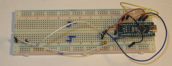
Photos of the hardware:
... but you do not understand:
- What is it?
- Is it working?
- What are his options?
I've had it, but yesterday a lot happened ...
The idea to build the CVC with the help of the MK appeared a long time ago, and they just came to realize their hands.
')
What to do?
I chose Arduino Nano as a controller because:
- There is a USB and, equally important, you don’t need to study it;
- Comfortable, small, not very expensive;
- There are no speed requirements, so STM32 is not needed;
- Very easy to program;
- Output voltage 5 V.
Diagram of the measuring part:
We supply voltage to In1 and In2 and, as a result, we must plot the current through UD (Unknown Device) = (U Out - U Out2 ) / R1 on voltage on it = U Out1 - U Out
Since we have a 5 V circuit, for simplicity, we limit ourselves to the IVC in the range from -5 to 5 V, so as not to complicate the design.
There are no DACs in the bundle, so input signals can be generated either using PWM + low pass filter or using a digital potentiometer / external DAC. I first made the 1st option.
The final scheme was as follows:
The program for Arduino is so small that I will bring it right here:
Program
void setup() { Serial.begin(115200); analogReference(EXTERNAL); // Aref 5 DDRD |= (1 << 2) | (1 << 3); TCCR2B |= (0 << CS22)|(0 << CS21)|(1 << CS20); // prescaler = 1. 13 TIMSK2 |= (1 << TOIE2)|(1 << OCIE2A); // TCCR2A &= ~(3); // WGM20 = 0, WGM21 = 0 TCCR2B &= ~(1 << 3); // WGM22 = 0 OCR2A = 128; sei(); } ISR(TIMER2_OVF_vect) { PORTD |= 1 << 2; PORTD &= ~(1 << 3); } ISR(TIMER2_COMPA_vect) { PORTD |= 1 << 3; PORTD &= ~(1 << 2); } int analogAVG(int channel){ uint32_t summ; uint16_t count = 50; for(uint8_t i = 0; i < count; i++) summ += analogRead(channel); return summ / count; } void loop() { OCR2A += 1; if(!OCR2A) // delay(100); Serial.print(OCR2A); Serial.print(":"); Serial.print(analogAVG(0)); Serial.print(":"); Serial.print(analogAVG(1)); Serial.print(":"); Serial.println(analogAVG(2)); } Drawing WAH made in C # partially copying the code from the previous project.
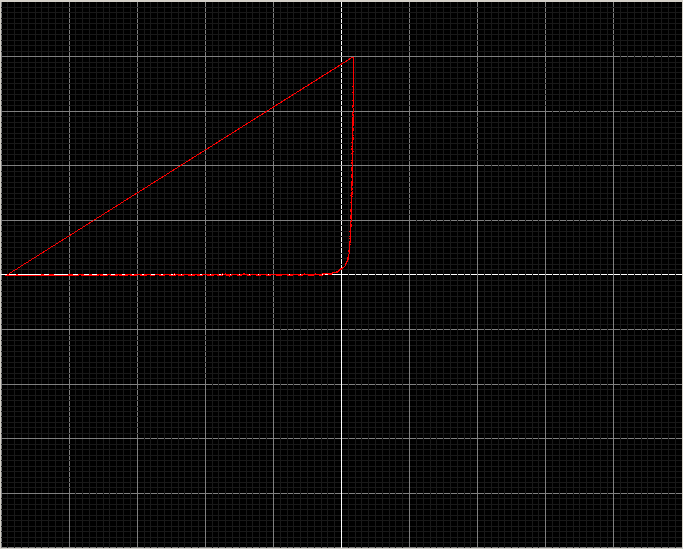
Several WAH obtained using the device
Bright vertical lines every 1B, bright horizontal lines every 100 µA.
The brightest vertical and horizontal lines are zeros.
Diode 1N4148:

Diode 1N5817:
See how at zero voltage the current is positive? What do you think, why?
Unknown LED:

680 ohm resistor:

The brightest vertical and horizontal lines are zeros.
Diode 1N4148:
Diode 1N5817:
See how at zero voltage the current is positive? What do you think, why?
Answer
PWM gives voltage fluctuations. When measuring the voltage, they are averaged and it turns out to be 0, and the current is rectified by a diode and after rectification and averaging it turns out to be significantly larger than zero.
Unknown LED:
680 ohm resistor:
Total
Without claiming the accuracy of the device from the Arduino Nano, 2 capacitors and 3 resistors allows you to compare the current-voltage characteristics of different two-terminal. Among the shortcomings can be noted:
- Low voltage range. If you expand the range, the number of elements increases significantly.
- Noise PWM. It can be eliminated by increasing the capacitance of the capacitors, increasing the values of the resistors and installing additional filter cascades or by abandoning the PWM in favor of a separate DAC or digital potentiometer.
- Not visible small currents, such as reverse currents diodes. Also disposable disadvantage.
Photos of the hardware:
Source: https://habr.com/ru/post/369485/
All Articles