Homemade Bluetooth AB Class Amplifier with Power Management Automation
It all started with laziness.
Or rather, with Vega 50u-122s, inherited along with the acoustics Electronics 25as-033. And at first everything was fine. And then, stumbling over the wire, the laptop was killed. After that, the BT module appeared in Vega, and Vega learned how to switch on by connecting devices to this module.
Time passed and the quality was not enough. Then the first upgrade was made to Vega. Then the second. Then acoustics. Then ... Then the understanding came that it is necessary to do something qualitatively new. Well, when Vega began to wheeze and the prospect of a complete soldering of all electrolytes loomed ...
And the construction began ...
Those who are too lazy to read technical details and just want to see how it works - you can scroll to the end, there is a shortened video version for my channel.
')
This is not a story about how to solder this. This is not an instruction: there will be no diagrams, no description of the settings, and so on.
This will be a story about ideas and technologies that I use in my devices.
Ideas that I embodied myself, and which you may want to embody.
So.
Basic idea. I want an amplifier. But I do not want to be confused in the wires. This is not convenient and not as high quality as we would like. Need some kind of wireless solution.
Second idea. I don't want to run around and poke buttons somewhere. Especially if I want to listen to relaxing music before bedtime. Yes, I am a lazy brute, I want to lie on the sofa, press the power button of the laptop and that everything would turn on and play itself. And when I fall asleep and the laptop turns off with a script, it turns off after it.
The third idea. Timers. In other words - on the weekend I do not turn off the laptop for the night. And this means that if the power-on via bluetooth is implemented, then the amplifier will be turned on all night. Somehow it's not cool, considering that the filter capacitors are worn out first. And secondly, it is simply heated and devours electricity.
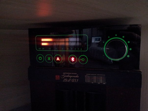
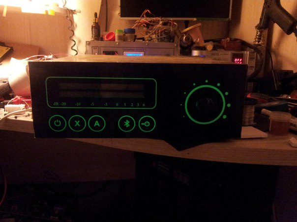
The fourth idea. I want an indicator. Big. Nice. Indicator. And then I found the IN-33, in the joy of writing the previous article . But not to say that it is big, so a trick was found with a film from the monitor, which visually “forks” the scale.
As a result , thinking about all the ideas, I came to the conclusion that a new amplifier should be made from scratch.
A Bluetooth module with apt-x was ordered:
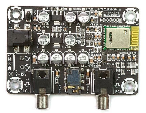
The following AB class amplifiers were ordered:

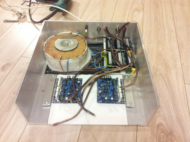
My grandfather bought a chic TOR at 200 watts for only 1000 rubles. with ready branches 2x26v and 2x12v. But the rest already did.
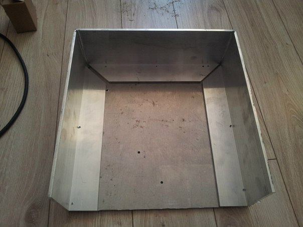
Housing
The case was made 300x300mm, the bottom - a dural plate 5mm thick on it is attached P figuratively bent corner 50 * 100 * 5mm, to which the transistors are attached through silicone pads and kit, and on top everything is tightened with bolts and a bar 20 * 6mm
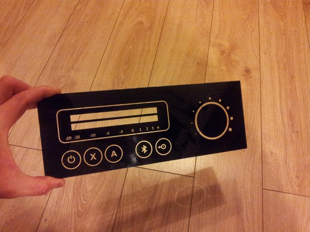
The front panel is mineral glass. Glass was taken from a photo frame for 300 rubles and clipped to the desired size with an ordinary glass cutter.
Then ordered silk screening. Moreover, I recommend not to cut on the paint and still do with the paint on the glass. Otherwise, sooner or later it will peel off and it will be a pity.
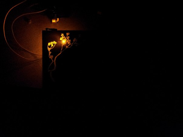
And, I recommend silk screen printing, because direct printing is garbage. I will explain:
Direct print on clearance (another project)
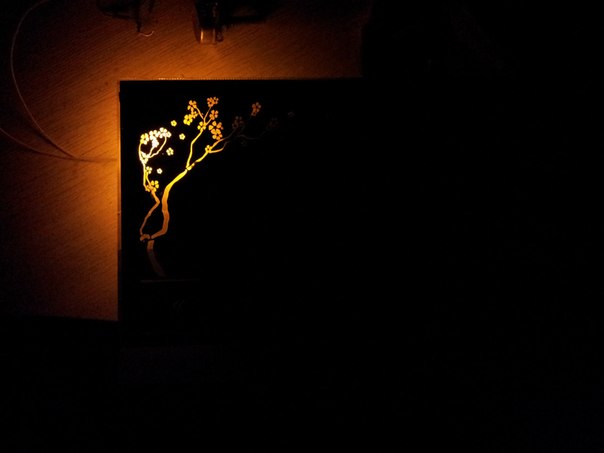
But the silk screen on the light:
The hole for the volume control is simply drilled on the glass with a drill.
Moreover, if you do it for the first time, I recommend to practice. It is not as fast and simple as it seems.
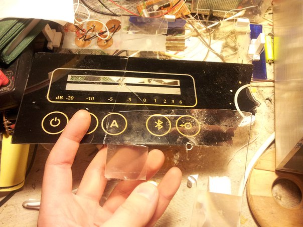
Then the sensors. White double adhesive tape was stuck on the glass. Then the copper foil was taken, on the one hand they were taped with adhesive tape, on the other side LUT was applied a drawing and was etched “through”.
It turned out like this:
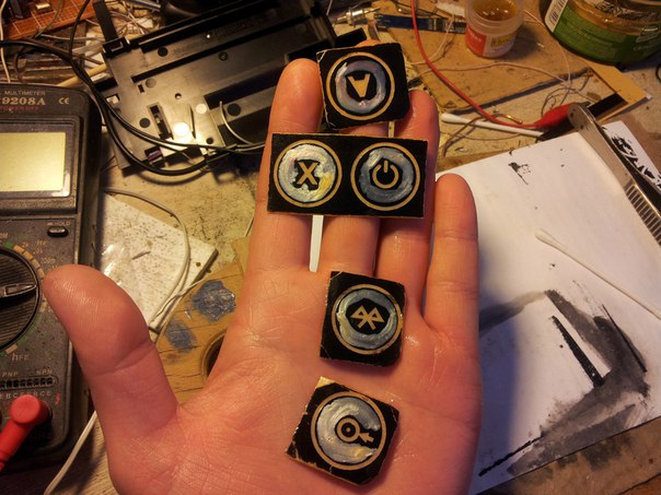
Then the foil was removed, everything was washed and it turned out:

These are ready preparations for sensors. Outlets were soldered to them and the whole structure was molded onto the front panel.
The exact alignment is important. Because everything should work for a clearance.
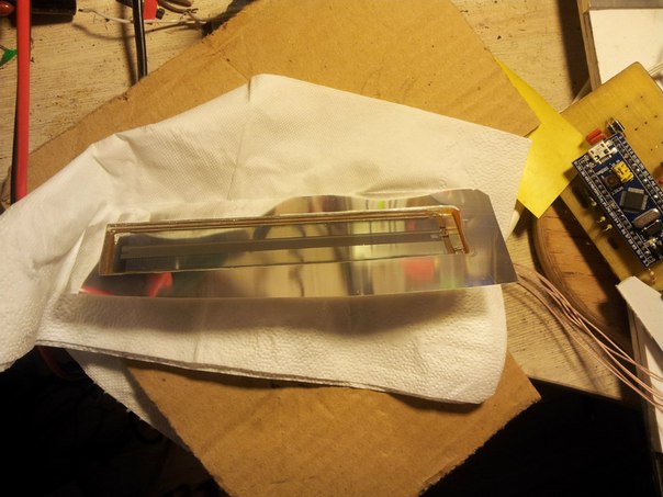
Next indicator. For the "expansion" of the scale, a prismatic substrate from the monitor matrix was used. And what would she lay down, glued superglue. Clay do not regret!
It is important to drive out all the bubbles and apply a film much wider than the indicator itself, otherwise the glue will spill over onto the opposite side and spoil everything.
Well, we must bear in mind that this film “forks” in only one plane, so it is important to maintain the strict horizontal position of the film prisms.
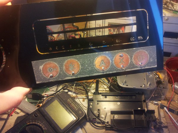
On this, if everything is illuminated from the inside, it will turn out like this:
But to make a uniform highlighting of characters is not as easy as it may seem.
The fact is that if you just take the LED and start to shine, the light illuminates part of the icon. Looks ugly. Moreover, if in the twilight it may still seem that everything is not bad, then in total darkness there will be a mass of flare shoals. Annoyed.
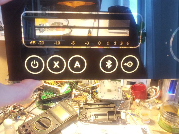
The output is as follows:
Foil was taken, twisted into a cone:
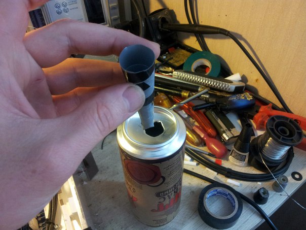
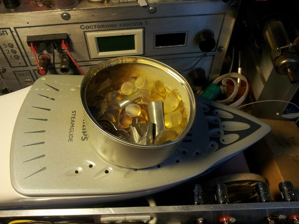
Then hot melt glue. I liked the iron for this, although my wife did not share my joy ...
Then it was poured and clipped to the size of the highlighted icon, a recess for the LED was drilled from the back side.

Well, it stuck. I pasted superglue. But then it would be thought that it would be better to simply heat up the glue of the cone and stick it straight on it.
And small gaps between the foil of the cone and the foil of the icons were plastered with putty and painted over. Putty - so that the paint does not flow between the filter and the sensor. After installing the LED icons - and they painted over the butt. Only in this way was I able to completely get rid of third-party covenants.
According to the scheme.
I'll start with power supplies. There are 2 of them.
The first is a power supply unit, not voltage stabilized. Assembled according to the scheme with 2 separate diode bridges, each arm has 33V of constant power and a 3x10,000 microfarad block of electrolytes, shunted with a 0.33 micron film and 1 microfarad ceramics. Also, the transformer windings themselves are shunted with 1 micron ceramics.
Power wiring: from transformer to bridges 2.5mm ^ 2, from bridges to capacitor banks - 4mm ^ 2, from capacitor units to plan amplifiers 6mm ^ 2.
The second is on duty. The Bluetooth module board must be constantly powered, so that you can always connect to it. Well, what would be understood that they connected to the amplifier and turn on the main power supply - it is also necessary to power the controller board. Therefore, the duty unit is low-power and pulse. Taken just charging from asus eee. Moreover, the analog part, namely the bluetooth module, is powered through an additional linear stabilizer.
Boards of amplifiers also had to completely re-solder. One board was nothing, but the second one was simply obscene. + further extended power tracks.
STM32 was chosen as the central “brain”. In principle, I could use the arduin on AVR, but meg firstly have few legs, and secondly only one ADC, which is why the indicator does not work well. The fact is that while we are digitizing one channel, the sound changes in both, and by the time the second is digitized, the difference is already quite large. This is striking and wanted to avoid it. Therefore, STM32.
The indicator scheme is not much different from the scheme from the previous article (by the way, it seems no one noticed a mistake in the scheme, but oh well).
Control.
Touch keys were needed. Having rummaged in articles about sensory for STM32, I found several options that I was not thrilled about.
First, I did not understand anything)))
Secondly, I had 5 buttons. Yes, and what would it work through a 3 mm mineral glass.
As a result, I had to taste the principle, experiment a bit and got the following code:
Where - ButZ - bare pin, in GPIO_Mode_Out_PP mode, the rest - read in GPIO_Mode_IN_FLOATING mode
The idea is simple. All reading sensors are connected to the bare pin through a 3MΩ resistor. Next, we give a unit to the bare pin and see how long it takes to charge up to the logical unit of the pin sensor. If the calibration time is longer, it means that you have to charge your finger, leaning against the sensor. So - there is a touch to the sensor.
Modes of operation
There are three of them.
First - Just off. And that's all.
The second mode is continuous power on. In this case, the amplifier always works. However, in case of idle time without sound, the level indicator turns off after a minute.
The third is “A”. And this is the main mode, automatic. If the Bluetooth input is selected, the amplifier is turned on and off by connecting the sound source. But if the device is connected and does not play - after 15 minutes the amplifier will go into standby mode. And, of course, if there is no sound for a minute, the level indicator turns off.
Moreover, it does not matter which audio input is used - whether it is bluetooth or external RCA input.
In general, the rest is standard. The volume knob is just a variable resistor. Just because the main volume control is assumed to be on the laptop and no one will go to the amplifier for this.
The result is beautiful. And it does not sound bad!
Video:
Or rather, with Vega 50u-122s, inherited along with the acoustics Electronics 25as-033. And at first everything was fine. And then, stumbling over the wire, the laptop was killed. After that, the BT module appeared in Vega, and Vega learned how to switch on by connecting devices to this module.
Time passed and the quality was not enough. Then the first upgrade was made to Vega. Then the second. Then acoustics. Then ... Then the understanding came that it is necessary to do something qualitatively new. Well, when Vega began to wheeze and the prospect of a complete soldering of all electrolytes loomed ...
And the construction began ...
Those who are too lazy to read technical details and just want to see how it works - you can scroll to the end, there is a shortened video version for my channel.
')
This is not a story about how to solder this. This is not an instruction: there will be no diagrams, no description of the settings, and so on.
This will be a story about ideas and technologies that I use in my devices.
Ideas that I embodied myself, and which you may want to embody.
So.
Basic idea. I want an amplifier. But I do not want to be confused in the wires. This is not convenient and not as high quality as we would like. Need some kind of wireless solution.
Second idea. I don't want to run around and poke buttons somewhere. Especially if I want to listen to relaxing music before bedtime. Yes, I am a lazy brute, I want to lie on the sofa, press the power button of the laptop and that everything would turn on and play itself. And when I fall asleep and the laptop turns off with a script, it turns off after it.
The third idea. Timers. In other words - on the weekend I do not turn off the laptop for the night. And this means that if the power-on via bluetooth is implemented, then the amplifier will be turned on all night. Somehow it's not cool, considering that the filter capacitors are worn out first. And secondly, it is simply heated and devours electricity.
The fourth idea. I want an indicator. Big. Nice. Indicator. And then I found the IN-33, in the joy of writing the previous article . But not to say that it is big, so a trick was found with a film from the monitor, which visually “forks” the scale.
As a result , thinking about all the ideas, I came to the conclusion that a new amplifier should be made from scratch.
A Bluetooth module with apt-x was ordered:
The following AB class amplifiers were ordered:
My grandfather bought a chic TOR at 200 watts for only 1000 rubles. with ready branches 2x26v and 2x12v. But the rest already did.
Housing
The case was made 300x300mm, the bottom - a dural plate 5mm thick on it is attached P figuratively bent corner 50 * 100 * 5mm, to which the transistors are attached through silicone pads and kit, and on top everything is tightened with bolts and a bar 20 * 6mm
The front panel is mineral glass. Glass was taken from a photo frame for 300 rubles and clipped to the desired size with an ordinary glass cutter.
Then ordered silk screening. Moreover, I recommend not to cut on the paint and still do with the paint on the glass. Otherwise, sooner or later it will peel off and it will be a pity.
And, I recommend silk screen printing, because direct printing is garbage. I will explain:
Direct print on clearance (another project)
But the silk screen on the light:
The hole for the volume control is simply drilled on the glass with a drill.
Moreover, if you do it for the first time, I recommend to practice. It is not as fast and simple as it seems.
Then the sensors. White double adhesive tape was stuck on the glass. Then the copper foil was taken, on the one hand they were taped with adhesive tape, on the other side LUT was applied a drawing and was etched “through”.
It turned out like this:
Then the foil was removed, everything was washed and it turned out:
These are ready preparations for sensors. Outlets were soldered to them and the whole structure was molded onto the front panel.
The exact alignment is important. Because everything should work for a clearance.
Next indicator. For the "expansion" of the scale, a prismatic substrate from the monitor matrix was used. And what would she lay down, glued superglue. Clay do not regret!
It is important to drive out all the bubbles and apply a film much wider than the indicator itself, otherwise the glue will spill over onto the opposite side and spoil everything.
Well, we must bear in mind that this film “forks” in only one plane, so it is important to maintain the strict horizontal position of the film prisms.
On this, if everything is illuminated from the inside, it will turn out like this:
But to make a uniform highlighting of characters is not as easy as it may seem.
The fact is that if you just take the LED and start to shine, the light illuminates part of the icon. Looks ugly. Moreover, if in the twilight it may still seem that everything is not bad, then in total darkness there will be a mass of flare shoals. Annoyed.
The output is as follows:
Foil was taken, twisted into a cone:
Then hot melt glue. I liked the iron for this, although my wife did not share my joy ...
Then it was poured and clipped to the size of the highlighted icon, a recess for the LED was drilled from the back side.
Well, it stuck. I pasted superglue. But then it would be thought that it would be better to simply heat up the glue of the cone and stick it straight on it.
And small gaps between the foil of the cone and the foil of the icons were plastered with putty and painted over. Putty - so that the paint does not flow between the filter and the sensor. After installing the LED icons - and they painted over the butt. Only in this way was I able to completely get rid of third-party covenants.
According to the scheme.
I'll start with power supplies. There are 2 of them.
The first is a power supply unit, not voltage stabilized. Assembled according to the scheme with 2 separate diode bridges, each arm has 33V of constant power and a 3x10,000 microfarad block of electrolytes, shunted with a 0.33 micron film and 1 microfarad ceramics. Also, the transformer windings themselves are shunted with 1 micron ceramics.
Power wiring: from transformer to bridges 2.5mm ^ 2, from bridges to capacitor banks - 4mm ^ 2, from capacitor units to plan amplifiers 6mm ^ 2.
The second is on duty. The Bluetooth module board must be constantly powered, so that you can always connect to it. Well, what would be understood that they connected to the amplifier and turn on the main power supply - it is also necessary to power the controller board. Therefore, the duty unit is low-power and pulse. Taken just charging from asus eee. Moreover, the analog part, namely the bluetooth module, is powered through an additional linear stabilizer.
Boards of amplifiers also had to completely re-solder. One board was nothing, but the second one was simply obscene. + further extended power tracks.
STM32 was chosen as the central “brain”. In principle, I could use the arduin on AVR, but meg firstly have few legs, and secondly only one ADC, which is why the indicator does not work well. The fact is that while we are digitizing one channel, the sound changes in both, and by the time the second is digitized, the difference is already quite large. This is striking and wanted to avoid it. Therefore, STM32.
The indicator scheme is not much different from the scheme from the previous article (by the way, it seems no one noticed a mistake in the scheme, but oh well).
Control.
Touch keys were needed. Having rummaged in articles about sensory for STM32, I found several options that I was not thrilled about.
First, I did not understand anything)))
Secondly, I had 5 buttons. Yes, and what would it work through a 3 mm mineral glass.
As a result, I had to taste the principle, experiment a bit and got the following code:
Sensor code reading
// #define SenseMinLevel 100 // #define ButZ GPIOA, GPIO_Pin_10 #define BtnOn GPIOB, GPIO_Pin_15 #define BtnOff GPIOA, GPIO_Pin_8 #define BtnAuto GPIOA, GPIO_Pin_9 #define BtnBT GPIOA, GPIO_Pin_3 #define BtnRCA GPIOA, GPIO_Pin_2 // volatile uint16_t CalibrateTimeB1 = 0; volatile uint16_t CalibrateTimeB2 = 0; volatile uint16_t CalibrateTimeB3 = 0; volatile uint16_t CalibrateTimeB4 = 0; volatile uint16_t CalibrateTimeB5 = 0; // uint8_t SenseButton(void) { uint16_t m; uint16_t b1 = 0; uint16_t b2 = 0; uint16_t b3 = 0; uint16_t b4 = 0; uint16_t b5 = 0; for (m = 0; m < 21; m++) { b1 += scan_sense_pin(BtnOff); b2 += scan_sense_pin(BtnOn); b3 += scan_sense_pin(BtnAuto); b4 += scan_sense_pin(BtnBT); b5 += scan_sense_pin(BtnRCA); } if (CalibrateTimeB1 == 0) { CalibrateTimeB1 = b1; CalibrateTimeB2 = b2; CalibrateTimeB3 = b3; CalibrateTimeB4 = b4; CalibrateTimeB5 = b5; } else { if (b1 > CalibrateTimeB1) b1 -= CalibrateTimeB1; else b1 = 0; if (b2 > CalibrateTimeB2) b2 -= CalibrateTimeB2; else b2 = 0; if (b3 > CalibrateTimeB3) b3 -= CalibrateTimeB3; else b3 = 0; if (b4 > CalibrateTimeB4) b4 -= CalibrateTimeB4; else b4 = 0; if (b5 > CalibrateTimeB5) b5 -= CalibrateTimeB5; else b5 = 0; } // if (b1 > SenseMinLevel || b2 > SenseMinLevel || b3 > SenseMinLevel || b4 > SenseMinLevel || b5 > SenseMinLevel) { if (b1 > b2 && b1 > b3 && b1 > b4 && b1 > b5) return 1; if (b2 > b1 && b2 > b3 && b2 > b4 && b2 > b5) return 2; if (b3 > b1 && b3 > b2 && b3 > b4 && b3 > b5) return 3; if (b4 > b1 && b4 > b3 && b4 > b2 && b4 > b5) return 4; if (b5 > b1 && b5 > b3 && b5 > b4 && b5 > b2) return 5; } return 0; } uint16_t scan_sense_pin(GPIO_TypeDef* port, uint16_t pin) { uint16_t ret = 0; GPIO_ResetBits(ButZ); delay_t(1800); GPIO_SetBits(ButZ); while (!GPIO_ReadInputDataBit(port, pin) && ret < 500) { ret++; } GPIO_ResetBits(ButZ); return ret; } void delay_t(uint32_t ms) { // nCount=(RCC_Clocks.HCLK_Frequency/1000)*ms; // for (; nCount!=0; nCount--); for (; ms!=0; ms--); } Where - ButZ - bare pin, in GPIO_Mode_Out_PP mode, the rest - read in GPIO_Mode_IN_FLOATING mode
The idea is simple. All reading sensors are connected to the bare pin through a 3MΩ resistor. Next, we give a unit to the bare pin and see how long it takes to charge up to the logical unit of the pin sensor. If the calibration time is longer, it means that you have to charge your finger, leaning against the sensor. So - there is a touch to the sensor.
Modes of operation
There are three of them.
First - Just off. And that's all.
The second mode is continuous power on. In this case, the amplifier always works. However, in case of idle time without sound, the level indicator turns off after a minute.
The third is “A”. And this is the main mode, automatic. If the Bluetooth input is selected, the amplifier is turned on and off by connecting the sound source. But if the device is connected and does not play - after 15 minutes the amplifier will go into standby mode. And, of course, if there is no sound for a minute, the level indicator turns off.
Moreover, it does not matter which audio input is used - whether it is bluetooth or external RCA input.
In general, the rest is standard. The volume knob is just a variable resistor. Just because the main volume control is assumed to be on the laptop and no one will go to the amplifier for this.
The result is beautiful. And it does not sound bad!
Video:
Source: https://habr.com/ru/post/369323/
All Articles