Intel Edison based climate control model
Today we will create a climate control system (CCM). Of course, not real, but only a model. But it will have all the properties of a large system. Have a heating element, ventilation and, among other things, can be controlled both manually and via the Internet using the cloud.
In this system, the incandescent lamp emulates the CCM in heating mode, and the fan in cooling mode. The lamp turns on for heating, and heats the temperature sensor. When the temperature reaches the maximum threshold, a command from the cloud turns off the lamp and turns on the fan until the temperature drops below the minimum threshold.
The control part is in the cloud, so changes in threshold values can be performed remotely. You can also turn the fan on and off with the button manually. The program is written in JavaScript using Intel XDK IoT Edition. Download the Intel XDK IoT from https://software.intel.com/ru-ru/iot/software/ide .
Components Used:
- Intel Edison board with power supply.
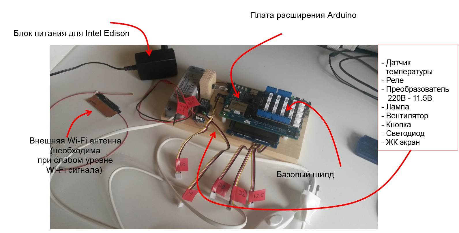
- External Wi-Fi antenna (if necessary).
- From the Grove Starter Kit:
- Basic Shield Seeed Studio.
- Temperature sensor.
- Relay.
- Button.
- Light-emitting diode.
- LCD screen.
- Incandescent lamp with power supply.
- Fan 5 V.
')
Most of the sensors in the Grove Starter Kit are designed to be easy to connect. To do this, it is enough to connect the cable with one side to the sensor and the other to the slot located on the top of the base shield. Of course, always check that the board is de-energized when you connect the wires and sensors. Also install on the shield the voltage of 5 V, which is required for sensors from this project.
You can read more about the basic set in the article IoT Ingredients of Fast Food Delicacies: Intel Edison + Intel XDK + JavaScript + Grove Kit .
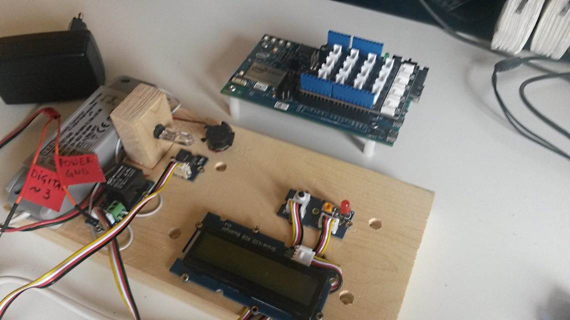
Connection diagram of all sensors
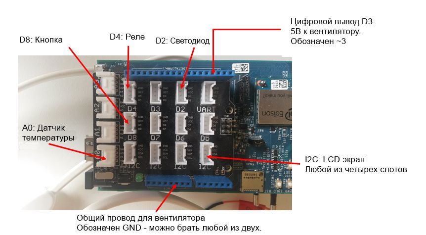
All the sensors described below are connected to the following connectors on the board:
temperature sensor
The most important part of the device, the temperature sensor, must be connected to the analog input A0. The temperature will be stored in degrees Celsius. Make sure that the sensor is located next to the heating lamp so that it reacts faster to changes in its temperature.
Button
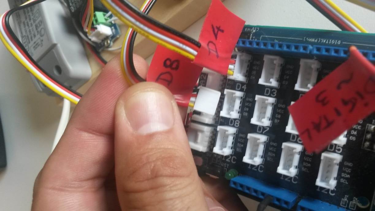
Connect a button to the D8 digital input. When you hold the button down for a second, the fan will turn on or off.
Light-emitting diode
The LED is a fan indicator. If it is lit, then the fan is working. LED is connected to D2.
Fan

The fan is not included in the Grove Starter Kit, so connecting it will be a little more difficult. The voltage of 5 V for the fan must be obtained from the digital contact D3, indicated on the board "~ 3". Take the common wire from the “Power GND” connector located on the other side of the board. Make sure that you are not confused, as an error can cause a short circuit and burn the device. Point the fan at the heat lamp so that it cools it when it is running.
It is important to pay attention to the following. Since the fan is connected directly to the digital pin, which has a load capacity of about 30 mA, it is necessary to choose a motor with a lower current consumption or make the connection similar to a glow lamp through a relay or, which is a little more difficult, but more correctly, using a motor driver.
Relay and heater lamp
The relay is connected to the D4 connector and controls the heater lamp. The lamp needs its own power supply, since it needs more than 5 volts on the Intel Edison board. Thus, the relay will work as an electronic switch between the board and the lamp. To connect the lamp to the relay, connect the NO contact (it is on the left) to the positive contact of the lamp and the CO contact (on the right) to the positive contact that matches the power supply. Connect the common wire of the lamp with the common wire of the power supply unit directly or, in simple terms, insert the relay into the open circuit of the lamp power supply.
LCD screen
The screen can be connected to any of the four I2C connectors. It displays the temperature value, and its backlight color can be green, orange, or red, depending on the thresholds set (below 30 — green, between 30 and 40 — orange, above 40 — red).
Power supplies
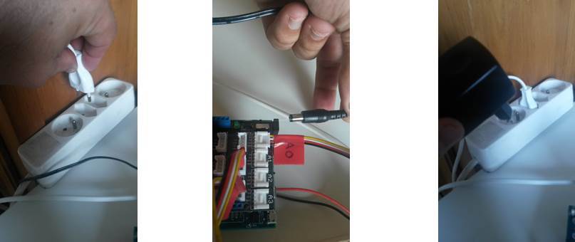
Now you can connect the voltage to the board and the lamp. Connect the 220 V converter -> 11.5 V to the lamp; it won't work until the Intel Edison board turns on the relay. Then connect the connector from the power supply to the board and insert the power supply itself into the power outlet. The green light should come on.
Connect to computer
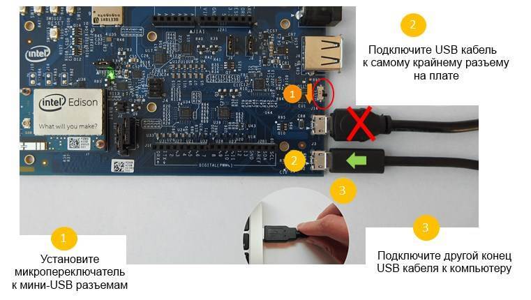
Now you need to configure Intel Edison to connect to a local Wi-Fi network. Make sure that the microswitch (1) on the board is set towards the micro USB connectors. Connect the micro USB cable at one end to the edge connector on the board (2) and the other to the computer (3). This will ensure connection through the terminal (PuTTY program). It is not necessary to use a second micro USB slot, as it is used to supply power, if there is no power supply, Ethernet, filling the Arduino with sketches and connecting external storage devices.
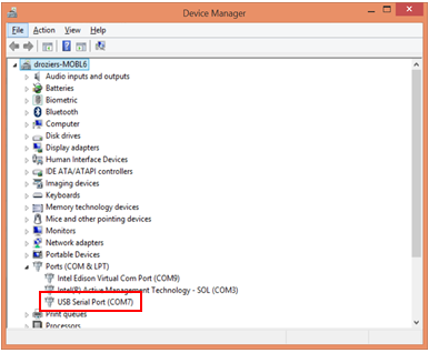
Instructions for Windows users
a. When you plug in the USB cable, the Edison board will appear in the Device Manager in the Ports (COM and LPT) section as “USB Serial Port”. Remember his number, we will need it later.
b. Download the PuTTY program to your computer to create a serial connection with the board.
with. Open PuTTY, select the type of Serial connection, enter the COM port number obtained from the first step. In our case, this is COM7. The speed is 115200. Click Open.

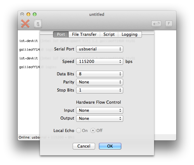
Mac user manuals
a. Open a terminal window (use Spotlight with the string 'terminal' to find it). Enter the command:
ls /dev/tty.*

In the list of connected devices, find the device that contains cu.usbserial or tty.usbserial. In the picture above, this device has the name /dev/tty.usbserial-A502YSYU
b. Download goSerial to create a serial connection between the computer and the board.
c. Open goSerial, select “Serial Port” - “usbserial”, set the speed to 115200 and click “OK”.
Customization
After these steps, the serial terminal window should appear. If nothing, press Enter, possibly twice. If you see the scrolling text, then the board is still loading, it usually takes less than a minute.
After the download is complete, login to the board. If you have not yet configured your board, use root without a password.
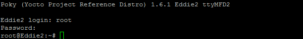
Set a password using the command
configure_edison --setup to set the root password. This must be done, otherwise the connection to the board via the Intel XDK will not work.
Connect to a Wi-Fi network
Enter:
configure_edison --wifi after the scan, you will see a list of available Wi-Fi networks.
If your network is not listed, you may have it hidden. If the Wi-Fi signal is weak, you can use an external antenna by connecting it to the appropriate connector on the Intel Edison board.

Select your network or hidden network - hidden. You will be asked if you specified the network correctly. Press Enter. If you choose a hidden network, enter its name. Enter the network password, if necessary. Now the board is connected to your Wi-Fi network.
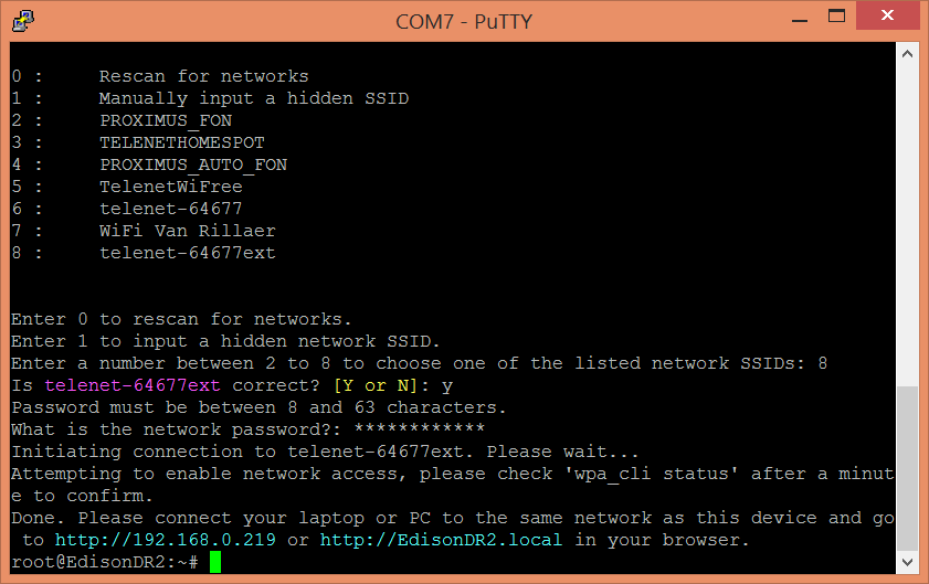
You can make sure that the board is connected normally by logging into the browser at:
http: // payment_addressfrom a computer that is on the same local network as the board. In the example in the picture this is:
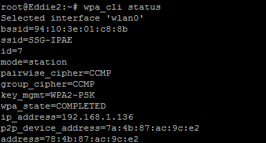
http://192.168.0.219Or type in the console:
wpa_cli status and make sure that the status is wpa_state = COMPLETED and the IP address is assigned.
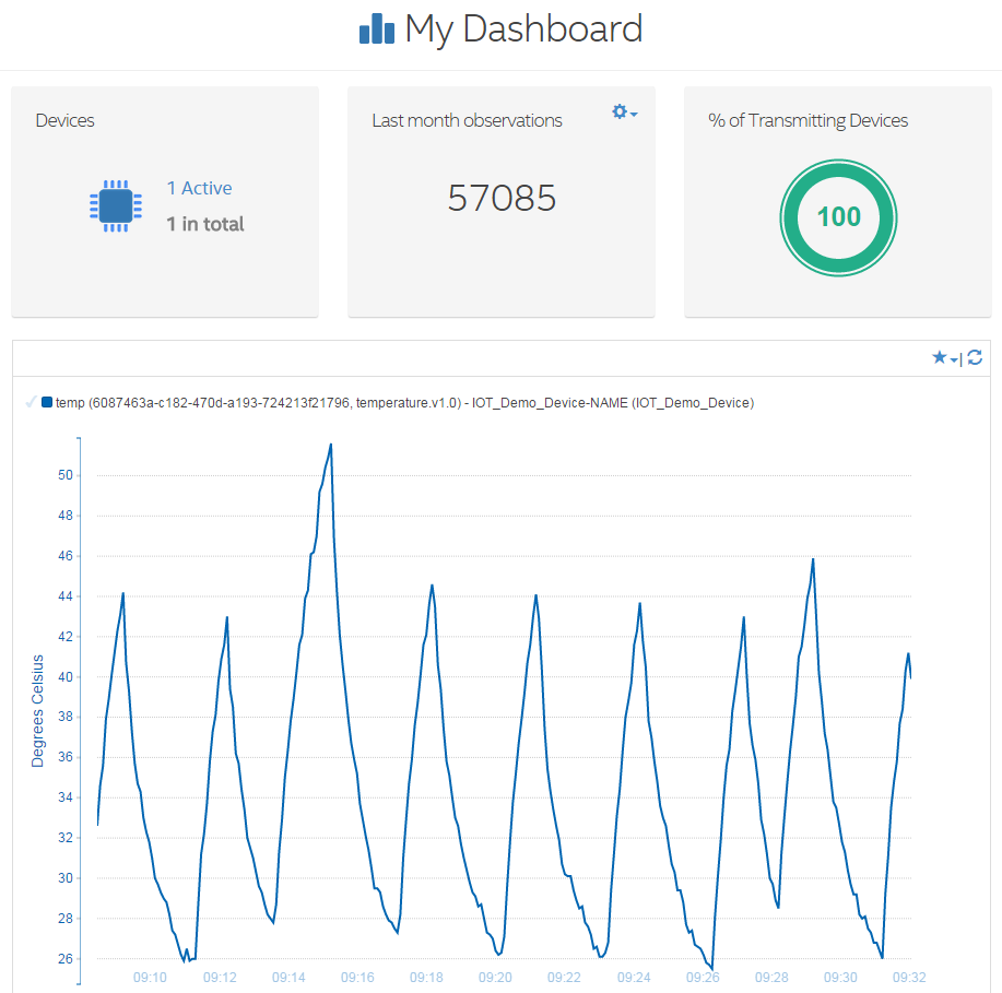
IoT cloud
The data and rules for managing our system are stored in the Intel IoT Analytics cloud. Every five seconds, Intel Edison sends the recorded temperature to the cloud, where it is displayed on the graph. The system in the cloud also checks temperature thresholds and, if necessary, sends a signal back to the Intel Edison board.
Site IoT agent dashboard.us.enableiot.com/ui/auth#/login
If you do not have an account yet, you have not installed the IoT agent on the Intel Edison board or have not activated the devices, see the configuration instructions in the Intel® IoT Platforms articles : Getting Started: Cloud Analytics and Intel Edison. Work with the cloud Intel IoT Analytics: registration and sending data .
The IoT agent already has several standard components for data collection. Temperature.v.10 and powerswitch.v1.0 are well suited for our climate control system. To register them, enter in the terminal window:
iotkit-admin register temp temperature.v1.0 iotkit-admin register relay powerswitch.v1.0 You will also need to establish on the site rules for the fan and heating lamps.
Cloud IoT - control installation
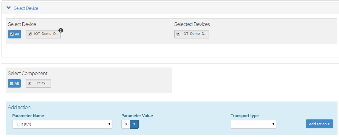
Click the button at the top right to show the menu on the side and then click on “Control”. A control window will open to send commands to the board. In the "Select Component" section, select your "relay" device. Indicate “LED (0,1)” as the name of the parameter “Parameter Name”, set the value of the parameter “Parameter Value” to “1”, then click on add action “Add action”. Click save as a complex “Save as complex command” command and name it “ventilator_ON”. Repeat this again, just enter the value “0” and name it “ventilator_OFF”.
IoT cloud - setting rules
Now you are ready to create rules for triggering commands. Click “Rules” on the sidebar to open the “My Rules” window, which shows Active (Active) and Archived rules. We will have two rules. One for temperatures below 30 degrees, which sends a notification to the board that you need to turn off the fan and turn on the lamp. Another for temperatures above 40 degrees. It sends a notification to turn on the fan and turn off the heat lamp.
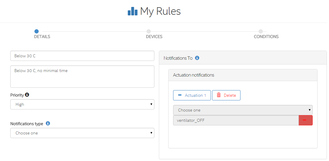
To create a “Below 30 C” rule (Below 30), click “Add a rule”. Give it a name, a description, a priority, and select the type of notification Actuation. Select the action "ventilator_OFF". Click Next and select your Intel Edison device. Click Next again and select “Enable Automatic Reset”, select “temp” as “Monitored Measure” and set “Trigger When” when “Basic Condition” is set to “<30” . Then click Done. Repeat for the “Above 40” rule (greater than 40), but set the action to “ventilator_ON” and select “> 40” for “Trigger When”.

Source code main.js for Intel® XDK
var mraa = require('mraa'); var dgram = require('dgram'); var mqtt = require('mqtt'); var fs = require('fs'); var upm_lcd = require ('jsupm_i2clcd'); var tempSensor = new mraa.Aio(0); // temperature sensor connected to analog IO pin 0 var powerswitch = new mraa.Gpio(8); // push button connected to digital IO pin 8 var led = new mraa.Gpio(2); // LED connected to digital IO pin 2 var ventilator = new mraa.Gpio(3); // ventilator connected to digital IO pin 3, // ie red cable ( 5 V ) to GPIO 3 on breakout board // and black cable ( ground ) to GND. var relay = new mraa.Gpio(4); // relay connected to digital pin 4 var lcd = new upm_lcd.Jhd1313m1(6,0x3E, 0x62); // LCD connected to the I2C bus, any connector on I2C will do. powerswitch.dir(mraa.DIR_IN); led.dir(mraa.DIR_OUT); ventilator.dir(mraa.DIR_OUT); relay.dir(mraa.DIR_OUT); // Touch Sensor Parameters var ventilatorON = 0; /* for this demo, ventilatorON is equivalent to light ( =heat source ) off */ var switchstate = 0; // Temperature Sensor Parameters var B = 3975; // Create MQTT Client var mqttClient = mqtt.createClient(1884); // Create UDP Client var udpClient = dgram.createSocket('udp4'); // UDP Options var rec_port = 41235; // LCD Parameters var lcdMessage = ""; // LCD Setup lcd.write("Intel Edison"); lcd.setCursor(1,0); lcd.write("TEMP: "); led.write(0); ventilator.write(0); relay.write(1); // Start Activities touchActivity(); lcdTempActivity(); function touchActivity() { switchstate = powerswitch.read(); //read the digital value of the pin if(switchstate == 1 ) /*change ventilatorstate */ { if ( ventilatorON == 0 ) { relay.write(ventilatorON); ventilatorON = 1; } else { relay.write(ventilatorON); ventilatorON = 0; } led.write(ventilatorON); ventilator.write(ventilatorON); } //check every second ( = 1000 millisec ) for status of the switch. setTimeout(touchActivity,1000); } function lcdTempActivity() { // Get temperature var reading = tempSensor.read(); // Get the resistance of the sensor var resistance = (1023 - reading) * 10000 / reading; // Convert to temperature via datasheet var temperature = (1 / (Math.log(resistance / 10000) / B + 1 / 298.15) - 273.15).toPrecision(3); lcdMessage = temperature + " C"; lcd.setCursor(1,6); lcd.write(lcdMessage); if(temperature > 40 ) { lcd.setColor(255,0,0); // Color screen red above 40 degrees } else if(temperature > 30) { // color screen orange above 30 (and below 40 ) // -- zone where ventilator will switch on automatically // -- need 2 rules in IOT Analytics tool. lcd.setColor(255,100,0); } else { lcd.setColor(0, 255, 0); //Green as long as temp is below 30 } // Send observation to the cloud sendObservation("temp", temperature, new Date().getTime()); setTimeout(lcdTempActivity,5000); /* update tempearture every 5 sec */ } // Send observation to the cloud (MQTT) function sendObservation(name, value, on) { var msg = JSON.stringify({ n: name, v: value, on: on}); //console.log("Sending observation: " + msg); mqttClient.publish("data", msg); } // listen for UDP message from local agent udpClient.on("error", function (err) { console.log("udpClient error:\n" + err.stack); udpClient.close(); } ); udpClient.on("message", function (msg, rinfo) { // ventilator is the component defined in the Analytics tool var sensorName = "LED"; console.log("udpClient got: " + msg + " from " + rinfo.address + ":" + rinfo.rec_port); // Ignore messages unless they are local if(rinfo.address != "127.0.0.1") { console.log("Ignoring remote UDP message"); return; } var js = JSON.parse(msg); var component = js['component']; var command = js['command']; var argvArray = js['argv']; console.log("component: " + component); console.log("command: " + command); for(var i = 0; i < argvArray.length; i++) { var name = argvArray[i]['name']; var value = argvArray[i]['value']; console.log("name: " + name); console.log("value: " + value); if (name == sensorName) { console.log("cloud (de)activation command for ventilator received"); if(parseInt(value) == 1 ) /*switch ventilator ON */ { if ( ventilatorON == 0 ) { relay.write(ventilatorON); ventilatorON = 1; led.write(ventilatorON); ventilator.write(ventilatorON); } } else { if( ventilatorON == 1 ) { relay.write(ventilatorON); ventilatorON = 0; led.write(ventilatorON); ventilator.write(ventilatorON); } } console.log("Ventilator state changed through cloud command to :" + ventilatorON ); } } }// function );// on message udpClient.on("listening", function () { var address = udpClient.address(); console.log("udpClient listening " + address.address + ":" + address.port); } ); udpClient.bind(rec_port); Ensure that the package.json file contains the MQTT in the dependencies.
{ "name": "blankapp", "description": "", "version": "0.0.0", "main": "main.js", "engines": { "node": ">=0.10.0" }, "dependencies": { "mqtt": "^0.3.8" } } About the author:
Dirk Rosiers is an IoT Developer evangelist for Intel at the SSG (Software and Services Group). He is engaged in technical support of the Internet developer of Things in the EMEA region (Europe, Russia, Middle East, Africa).
Source: https://habr.com/ru/post/369261/
All Articles