Three Five for Electronics
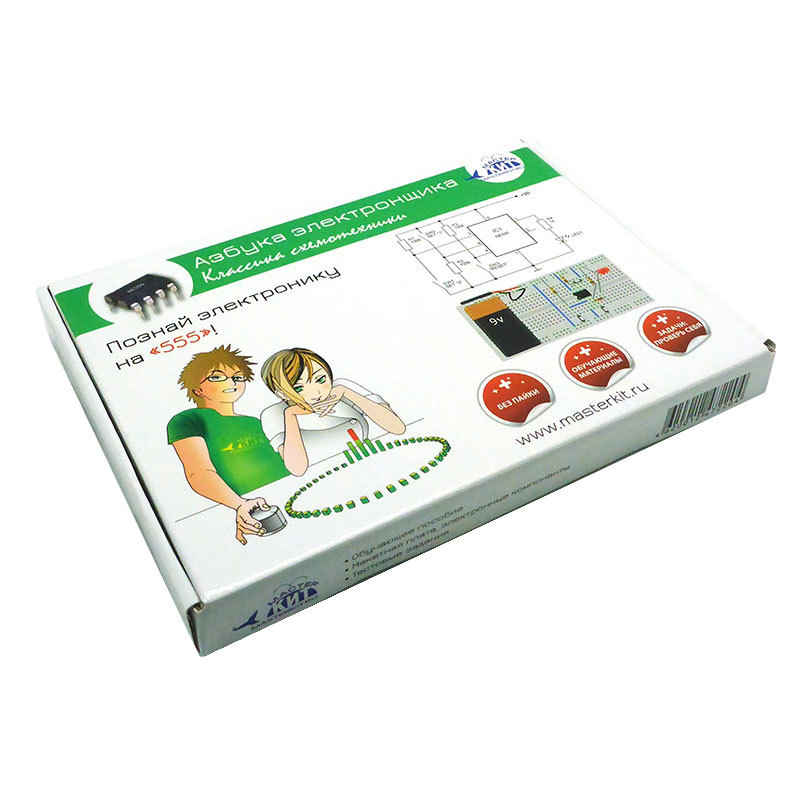
Master Keith, which produces a series of training kits for beginners under the general name “Alphabet of the Electronics Engineer”, of course, could not overlook such a well-known component as the “legendary” integrated timer NE555. And, if in the first set of “Basic circuit design” , 15 simplest circuits with the use of basic electronic components (resistors, capacitors, transistors, diodes) are considered, then the set, which we called the “Circuit design classic” , contains 20 NE555 timer circuits.
Few electronic components can boast the name "legendary". Yes, there were, there are and there will be popular components that are widespread over a period of time. But in order to remain fully up-to-date and in demand at the modern speed of scientific and technological progress - there are few of them! And one of these components is the NE555 integrated timer. Under this name in 1971, it was released by Signetics and since then it has been produced almost unchanged by many well-known manufacturers of electronic components. This certainly contributes to a very successful combination of functionality and price. Fives are traditionally included in the name of all manufacturers, except, perhaps, domestic. We have this chip is called 1006VI1.
The legendary timer still serves as a source of inspiration for many amateurs and professionals in the field of electronics. They have developed many useful and cheap solutions based on this analog chip.
')
All schemes, as in the previous set, are assembled on a solderless circuit board and are powered from a single 9V battery.

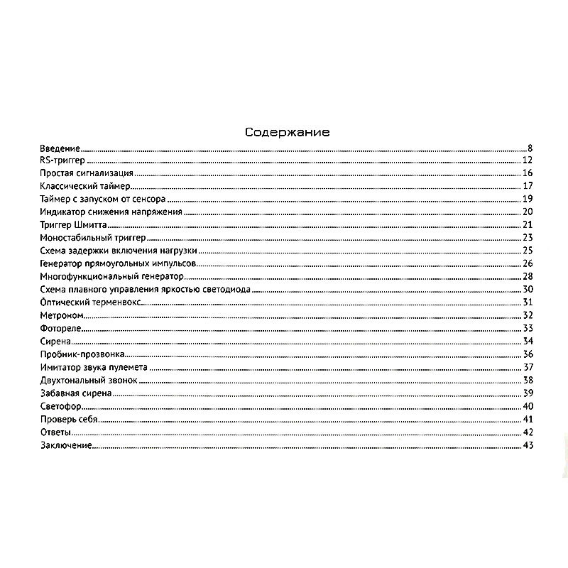
Schemes are selected for increasing complexity and cover all the functionality of the chip - from diagrams explaining the principle of operation of the NE555, to practical implementations of devices based on one or two timers: generators, time relay, alarm devices, sound modules, devices for delaying other
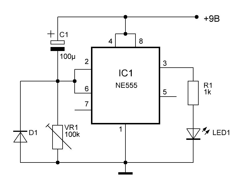
Let us give an example of the delayed switching on of acoustic systems in an audio amplifier to eliminate clicks and their failure. When power is applied to the circuit, the LED1 LED turns on after a time determined by the time constant of the C1, VR1 chain and can be adjusted over a wide range with the help of the VR1 trimming resistor. If instead of a resistor and an LED to output 3 chips, we connect an electromagnetic relay, we get a complete on-delay circuit.
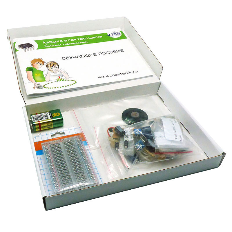
In the colorful tutorial, the dates of the descriptions of all electronic components that make up the kit: their appearance, schematic designation, marking. Therefore, even a novice electronics engineer will be easy to assemble any of the proposed 20 schemes.

In the manual, as before, we included a small theoretical part with the necessary explanations for each scheme, focusing on practical experience and results. In all schemes, any visual results of their work are provided - either LED light indication or sound with the help of low-power dynamics. Also in the manual there is a traditional section “Check yourself” with questions on the topic in question.

The total number of components included in the kit is about 100, in addition to the three NE555 timers. Using the breadboard and components, after studying the manual, you can independently develop and assemble your own schemes, based on the knowledge gained and the independent search for information in print publications and the Internet.
Thus, the new set of the Master Kit company, “The Alphabet of the Electronic Engineer - Classical Circuit Engineering” , being a logical continuation of the previous set of the series, can be recommended for independent study and consolidation of the theoretical knowledge of analog circuitry for students of schools, colleges and universities.
Few electronic components can boast the name "legendary". Yes, there were, there are and there will be popular components that are widespread over a period of time. But in order to remain fully up-to-date and in demand at the modern speed of scientific and technological progress - there are few of them! And one of these components is the NE555 integrated timer. Under this name in 1971, it was released by Signetics and since then it has been produced almost unchanged by many well-known manufacturers of electronic components. This certainly contributes to a very successful combination of functionality and price. Fives are traditionally included in the name of all manufacturers, except, perhaps, domestic. We have this chip is called 1006VI1.
The legendary timer still serves as a source of inspiration for many amateurs and professionals in the field of electronics. They have developed many useful and cheap solutions based on this analog chip.
')
All schemes, as in the previous set, are assembled on a solderless circuit board and are powered from a single 9V battery.
Schemes are selected for increasing complexity and cover all the functionality of the chip - from diagrams explaining the principle of operation of the NE555, to practical implementations of devices based on one or two timers: generators, time relay, alarm devices, sound modules, devices for delaying other
Let us give an example of the delayed switching on of acoustic systems in an audio amplifier to eliminate clicks and their failure. When power is applied to the circuit, the LED1 LED turns on after a time determined by the time constant of the C1, VR1 chain and can be adjusted over a wide range with the help of the VR1 trimming resistor. If instead of a resistor and an LED to output 3 chips, we connect an electromagnetic relay, we get a complete on-delay circuit.
In the colorful tutorial, the dates of the descriptions of all electronic components that make up the kit: their appearance, schematic designation, marking. Therefore, even a novice electronics engineer will be easy to assemble any of the proposed 20 schemes.
In the manual, as before, we included a small theoretical part with the necessary explanations for each scheme, focusing on practical experience and results. In all schemes, any visual results of their work are provided - either LED light indication or sound with the help of low-power dynamics. Also in the manual there is a traditional section “Check yourself” with questions on the topic in question.
The total number of components included in the kit is about 100, in addition to the three NE555 timers. Using the breadboard and components, after studying the manual, you can independently develop and assemble your own schemes, based on the knowledge gained and the independent search for information in print publications and the Internet.
Thus, the new set of the Master Kit company, “The Alphabet of the Electronic Engineer - Classical Circuit Engineering” , being a logical continuation of the previous set of the series, can be recommended for independent study and consolidation of the theoretical knowledge of analog circuitry for students of schools, colleges and universities.
Source: https://habr.com/ru/post/369065/
All Articles