A thousand first way to control the rosettes
I was interested in a DIY gadget called RF-TOY, you can buy it here, from the author of this open source project or at home called MP1516 RFToy - Universal, Arduino compatible radio module.
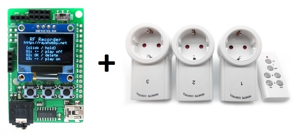
In fact, this is a specialized Arduino board on the ATmega 328P, 8 MHz, tuned for experiments with data transmission over the radio channel, either a budget 433 MHz, or “advanced” 2.4 GHz. Bribed by the presence of a small, but graphic screen and the ability to visualize processes. The study began with a simple - radio outlet control.
The module itself is the size of a matchbox, complete with an additional 433 MHz receiver and transmitter with amplitude modulation (ASK), a lithium battery.
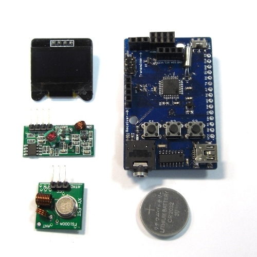
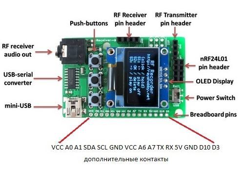
To make the 433 receiver work, you need 5V power from USB. There is also a connector for the installation of the radio module nRF24L01 (purchased separately) and a number of free and service legs of the microcontroller, displayed on the edge of the board. Appointment in the figure.
')
More information can be found on these sites. There is also a good movie. In English, but in principle everything is clear. Connecting an Arduino IDE without features, via USB, a CH340 USB Adapter Chip. The board is stitched as “Arduino Mini w / ATmega328”, 8 MHz, and the libraries and examples are downloaded from GitHub and installed as standard.
I set up an example called RFToy_RFRecorder. This is a sketch that allows you to memorize up to 7 combinations of On / Off commands of the console, that is, you can take control of seven radio outlets or radio cartridges for light bulbs.
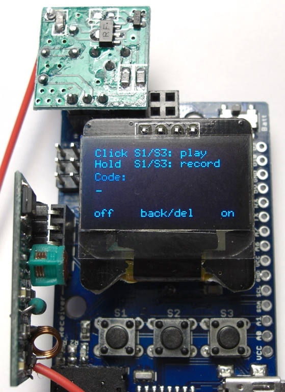
After switching on, the first screen looks like this:
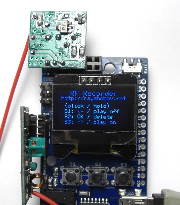
Bribe carefully described functions of each button of the module, you will not forget.
The length of pressing buttons is different. Click and hold (long press).
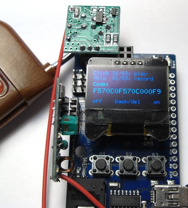
I clicked "OK" and got into the work menu, where with the help of long presses on the buttons S1 or S2 you can write down the codes of the on and off buttons. And short clicks can then be managed. There is also a hint on the screen. I clamp S3 and get into the recording mode of the power button
Write the button code, bring the keychain (the remote is also in my kit ), I click ...
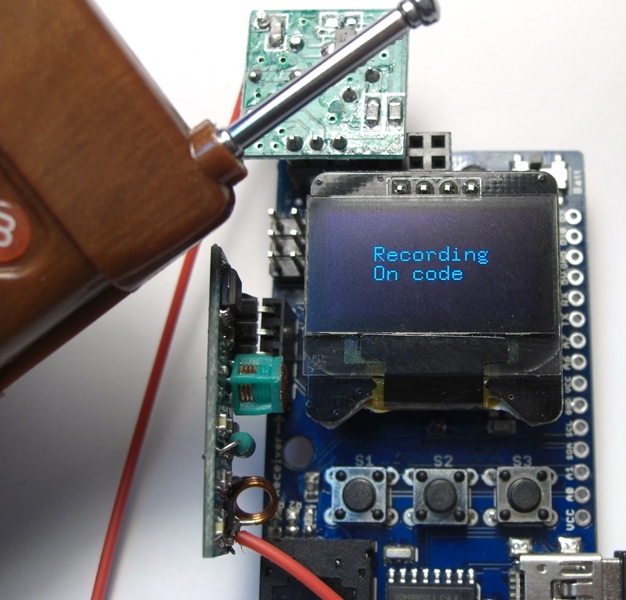
The code was considered and the screen looks like this:
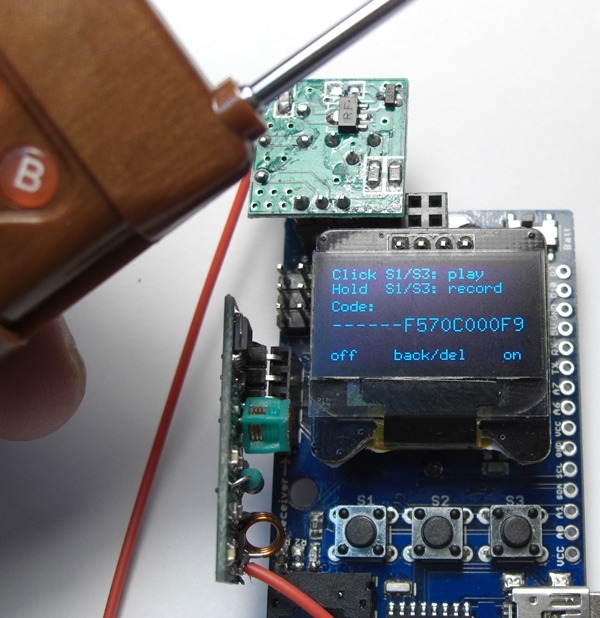
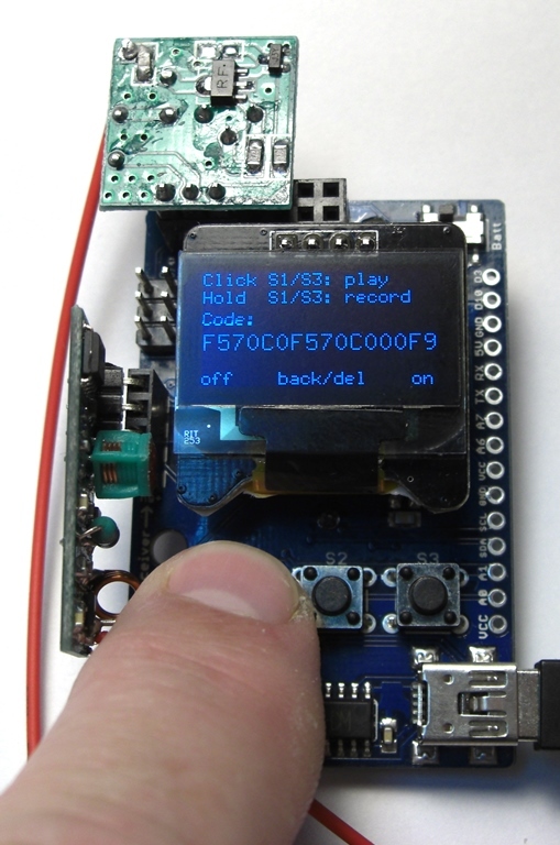
Now we will write down the button code for the shutdown button, pinch the left button of the board.
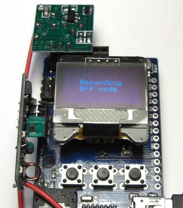
The shutdown code is written "on top" of the enable code and the total command line becomes:
It now remains with a short press of a button to turn the radio socket on and off from the RFToy module on and off.
Yes, check - it works!
Then you can fill all the memory cells of the module. Click "OK" select a free cell and repeat the entry
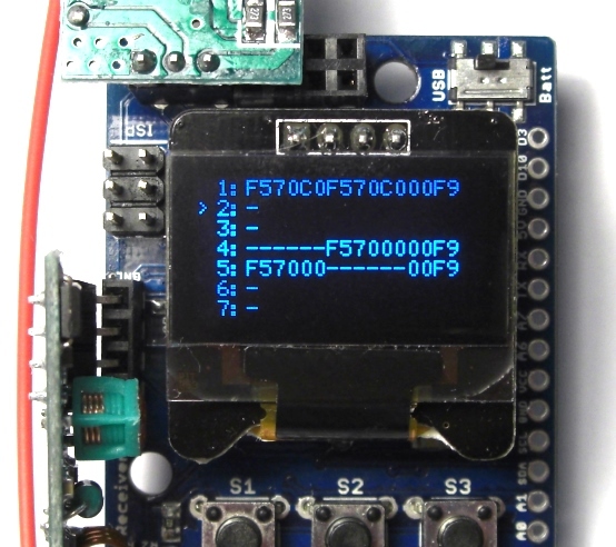
Below you can see how the cells are filled. The second line refers to the adjacent button of the remote.
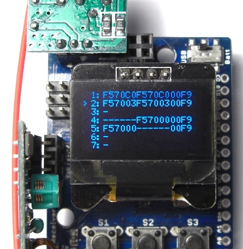
Now, switching between lines, you can select the desired control channel.
Interestingly, on lines 3 and 4, the on and off commands are written separately. Obviously at the end of the line we write the address of the device, and the button code is written, then in the first 6 familiarity, then in the second.
Let's see what is interesting in the sketch.
#include <SPI.h>
#include <RCSwitch.h>
#include "U8glib.h"
#include <avr / eeprom.h>
We see that popular libraries are used for displaying on the screen, controlling the data transfer of the RCSwitch and writing to the eeprom. Indeed, after turning off the power, the read data is not lost.
// determine the display to use. Resolution 128x64 points
U8GLIB_SSD1306_128X64 u8g (U8G_I2C_OPT_NONE);
Further, very neatly written code. First, all the necessary functions are described, such as determining the time for pressing a button, writing and reading an eeprom, recording and playing back the button code, displaying information on the screen, and others.
In the constant cycle, only the tracking of the control buttons is spinning.
Probably someone will want to take control of the module to external controls, for example, use a duplicate wall switch. You can do it like this:
1. Select the free Pin of the microcontroller by software we pull it up to 1, and with the switch we switch the input to the common wire (feed a logical 0) for the On state and open (return the logical one) for the Off state.
2. Next, you need to determine the line number (1-7) with the necessary code and write it into a variable ... although I don’t think that everyone is interested, if you have specific questions - please contact the Technical Support service Master Keith
with reference to this article. Let's figure it out.
Successes!
In fact, this is a specialized Arduino board on the ATmega 328P, 8 MHz, tuned for experiments with data transmission over the radio channel, either a budget 433 MHz, or “advanced” 2.4 GHz. Bribed by the presence of a small, but graphic screen and the ability to visualize processes. The study began with a simple - radio outlet control.
The module itself is the size of a matchbox, complete with an additional 433 MHz receiver and transmitter with amplitude modulation (ASK), a lithium battery.
To make the 433 receiver work, you need 5V power from USB. There is also a connector for the installation of the radio module nRF24L01 (purchased separately) and a number of free and service legs of the microcontroller, displayed on the edge of the board. Appointment in the figure.
')
More information can be found on these sites. There is also a good movie. In English, but in principle everything is clear. Connecting an Arduino IDE without features, via USB, a CH340 USB Adapter Chip. The board is stitched as “Arduino Mini w / ATmega328”, 8 MHz, and the libraries and examples are downloaded from GitHub and installed as standard.
I set up an example called RFToy_RFRecorder. This is a sketch that allows you to memorize up to 7 combinations of On / Off commands of the console, that is, you can take control of seven radio outlets or radio cartridges for light bulbs.
After switching on, the first screen looks like this:
Bribe carefully described functions of each button of the module, you will not forget.
The length of pressing buttons is different. Click and hold (long press).
I clicked "OK" and got into the work menu, where with the help of long presses on the buttons S1 or S2 you can write down the codes of the on and off buttons. And short clicks can then be managed. There is also a hint on the screen. I clamp S3 and get into the recording mode of the power button
Write the button code, bring the keychain (the remote is also in my kit ), I click ...
The code was considered and the screen looks like this:
Now we will write down the button code for the shutdown button, pinch the left button of the board.
The shutdown code is written "on top" of the enable code and the total command line becomes:
It now remains with a short press of a button to turn the radio socket on and off from the RFToy module on and off.
Yes, check - it works!
Then you can fill all the memory cells of the module. Click "OK" select a free cell and repeat the entry
Below you can see how the cells are filled. The second line refers to the adjacent button of the remote.
Now, switching between lines, you can select the desired control channel.
Interestingly, on lines 3 and 4, the on and off commands are written separately. Obviously at the end of the line we write the address of the device, and the button code is written, then in the first 6 familiarity, then in the second.
Let's see what is interesting in the sketch.
#include <SPI.h>
#include <RCSwitch.h>
#include "U8glib.h"
#include <avr / eeprom.h>
We see that popular libraries are used for displaying on the screen, controlling the data transfer of the RCSwitch and writing to the eeprom. Indeed, after turning off the power, the read data is not lost.
// determine the display to use. Resolution 128x64 points
U8GLIB_SSD1306_128X64 u8g (U8G_I2C_OPT_NONE);
Further, very neatly written code. First, all the necessary functions are described, such as determining the time for pressing a button, writing and reading an eeprom, recording and playing back the button code, displaying information on the screen, and others.
In the constant cycle, only the tracking of the control buttons is spinning.
Probably someone will want to take control of the module to external controls, for example, use a duplicate wall switch. You can do it like this:
1. Select the free Pin of the microcontroller by software we pull it up to 1, and with the switch we switch the input to the common wire (feed a logical 0) for the On state and open (return the logical one) for the Off state.
2. Next, you need to determine the line number (1-7) with the necessary code and write it into a variable ... although I don’t think that everyone is interested, if you have specific questions - please contact the Technical Support service Master Keith
with reference to this article. Let's figure it out.
Successes!
Source: https://habr.com/ru/post/368819/
All Articles