Smart House. Understanding the design of a low-voltage circuit system
The principle of connecting HDL Buspro to the local network
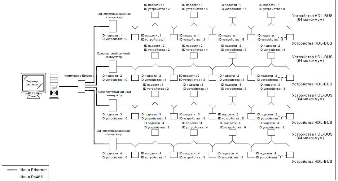
Different subnets can be connected by creating a local area network (UDP / IP) via a bus switch (no more than 255 subnets). In some cases, it is recommended to use a ring topology for the local network to increase the reliability of the entire structure.
Setting up devices with a switch function
So, take a few devices that can be used as a switch. Let it be:
- single port bus switch;
- hotel room management host: 48-channel host controller;
- 48-channel DMX scene controller with Ethernet port;
- 512-channel DMX scene controller;
- GPRS-controller messages (SMS-module);
- background music module.
When these devices are used as a switch, the device's subnet ID must be the same as other devices, otherwise the switch will not be able to communicate with devices of other subnets. For example, if the switch's subnet ID is 1, for other connected devices, the subnet ID should be -1.
Topology structure for a single bus network:

')
Example of device addresses:
The length refers to devices connected to one bus. It is recommended to connect no more than 32 devices to a 1000m long bus. To the bus 500m long - no more than 64.
Large bus / Ethernet network topology structure:

Principle of power system
Two power supplies are available: 750mA and 2400mA.

Bus current calculation method:
B = (B1 + B2 + Bn), where B1, B2 and Bn are the consumed currents of each of the bus devices, and B is the total current consumption of all bus devices. The capacity of the power supply unit is 1.2 times more than the total current consumption of all devices of the bus. When designing a long bus network, it is necessary to take into account the voltage drops, the operating voltage of the terminal device must be greater than 15V. There are several tire laying conditions. The CAT5E cable (UTP5) is used as a medium for data transfer on the bus. For the reliability of the communication system, it is necessary that the bus was separate from the high voltage cable, and also must be laid on a horizontal steel or PVC pipe.
The bus network must also have bus technology; serial connection is recommended. The ring is prohibited, and the connection according to the scheme of a star is not recommended, but not prohibited. If necessary, the star used the HDL bus hub for six ports to use a star; it allows you to implement a bus star topology for up to 12 devices.
Below is a clear example of the implementation of the DALI interface control. DALI (Digital Addressable Lighting Interface) - digital address control light. (Tridonikatko). This is the communication protocol of the controller and ballasts. A low-voltage cable is used to transmit the bus signal. All ballasts can be assembled into one network, get automatically addresses and can be grouped for control.

Actually, to implement DALI interface control, we will need an OPS server, a switch to which we connect a single-port switch, a relay module with the required number of channels, the DALI controller itself with the ability to connect up to 64 devices and a small 750mA power supply. From the interfaces, in my opinion, the best option would be a multifunctional DLP panel and a ceiling sensor that will contain all the IR commands we need.
In this article, programming issues will not be considered, a separate article will be devoted to this, in which we will also consider the topology of the DMX interface.
Source: https://habr.com/ru/post/368709/
All Articles