Z-Wave traffic light based on Z-UNO board
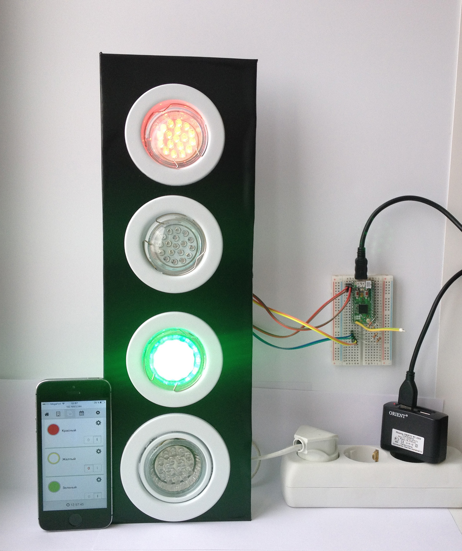
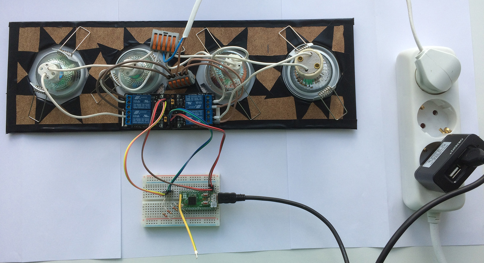
For children's games, I need a traffic light with radio control. I already have a Z-Wave RaZberry controller, so I decided to make a traffic light with control via Z-Wave. The essence is simple: 4 multi-colored light bulbs are controlled using 4 relays (the fourth is blue, turbo mode).
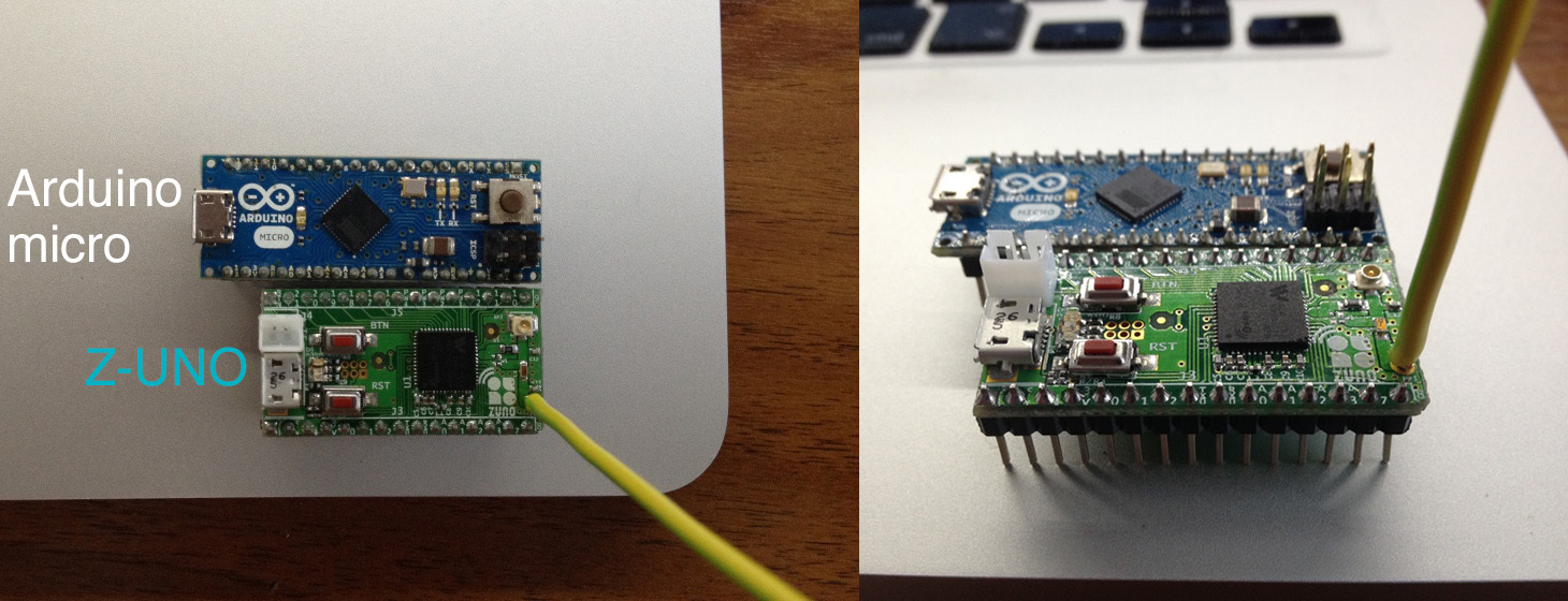
To develop my Z-Wave device with 4 relays, I chose the second version of the Z-UNO board, which has become more compact.
Programming and fill firmware implemented in the Arduino IDE. To work with Z-Wave, specific Z-Wave functions have been added to the Arduino syntax.
Relay modules are 5 volt, controlled by PC817C optocoupler (datasheet ), connected to the legs 9,10,11,12. It should be noted that the maximum current passing through the Z-UNO leg can be no more than 8mA, so we limit the current to 220 Ohm with a resistor.
The sketch is written in C with the ability to use Arduino functions and specific Z-Wave calls.

Sketch 4 channel Z-Wave relay
/ *
*
* 4 Relays controlled thouth resistors 220Omh and optocouplers 817C
* Off - HIGH
* On - LOW
* /
// Pins definitions
#define LedPin1 9
#define LedPin2 10
#define LedPin3 11
#define LedPin4 12
// Global variables to store data reported via getters
byte switchValue1 = 1;
byte switchValue2 = 1;
byte switchValue3 = 1;
byte switchValue4 = 1;
')
ZUNO_SETUP_SLEEPING_MODE (ZUNO_SLEEPING_MODE_ALWAYS_AWAKE);
// Set up 10 channels
ZUNO_SETUP_CHANNELS (
ZUNO_SWITCH_BINARY (getterSwitch1, setterSwitch1),
ZUNO_SWITCH_BINARY (getterSwitch2, setterSwitch2),
ZUNO_SWITCH_BINARY (getterSwitch3, setterSwitch3),
ZUNO_SWITCH_BINARY (getterSwitch4, setterSwitch4)
);
void setup () {
// set up I / O pins. Analog and PWM functions call
pinMode (LedPin1, OUTPUT);
pinMode (LedPin2, OUTPUT);
pinMode (LedPin3, OUTPUT);
pinMode (LedPin4, OUTPUT);
}
void loop () {
// Empty
}
// Getters and setters
void setterSwitch1 (byte value) {
digitalWrite (LedPin1, (value> 0)? LOW: HIGH);
switchValue1 = value;
}
byte getterSwitch1 () {
return switchValue1;
}
void setterSwitch2 (byte value) {
digitalWrite (LedPin2, (value> 0)? LOW: HIGH);
switchValue2 = value;
}
byte getterSwitch2 () {
return switchValue2;
}
void setterSwitch3 (byte value) {
digitalWrite (LedPin3, (value> 0)? LOW: HIGH);
switchValue3 = value;
}
byte getterSwitch3 () {
return switchValue3;
}
void setterSwitch4 (byte value) {
digitalWrite (LedPin4, (value> 0)? LOW: HIGH);
switchValue4 = value;
}
byte getterSwitch4 () {
return switchValue4;
}
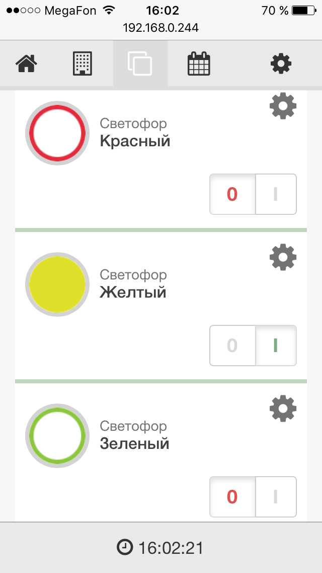
Fill the sketch in Z-UNO, then add our device to the Z-Wave controller. We customize the icons a bit and the control panel of the traffic light is ready.

On the phone, the RaZberry web interface doesn't look bad either.
Also, this traffic light can be controlled from other Z-Wave devices, for example, a Key Fob key fob with 4 buttons.

In the game, I myself will control the traffic light depending on the traffic situation, but with the help of additional sensors, schedules and RaZberry applications it would be possible to automate the system.

The Z-UNO board allows you to develop any type of Z-Wave devices: relays, dimmers, light sensors, movements, distances, and many others. Z-UNO is one of the cheapest Z-Wave devices. For 3000r you can make for example a 10-channel relay or a 10 channel RGBW module! It is very cool!
Source: https://habr.com/ru/post/368563/
All Articles