Lantern "Magic Lamp"
This is a story about the redesign of the LED flashlight. An unconventional highlight is present :) - warm tube analog solutions are applied!
A few years ago, when LED lights just started to appear in stores, I bought an LED digger at Okey. Large, with a pistol grip, conveniently lying in the hand, balanced. It had one 3-volt LED, a lead battery, and, as described, could stand on recharging without restrictions. It was what you need in the country. As we all know, in spite of the 21st century and the space ships plying the cosmos (C) - at a distance of more than 30 km from Moscow, the power supply becomes unreliable. Power networks disconnect electricity at any opportunity - in the rain, thunderstorm, heat and just like that. Usually on Saturday-Sunday for an hour or two, the electricity is cut off. Probably to train the population to survive in all conditions.
Therefore, the presence of a powerful, convenient flashlight, constantly charged and ready to go is practical.
')
Unfortunately, lead batteries have a limited service life of about three years, especially in standby mode with constant drip recharging. My flashlight was no exception, at some point I found that the battery does not hold a charge, but after a short time the voltage fell below the threshold of the LED.
Of course you could go to any store of radio components and buy a replacement battery. But a cursory study of the prices of such batteries did not arouse my enthusiasm. Having considered the question, I decided that in such a lamp it is reasonable to use lithium batteries of type 18650, remaining from the replacement of elements in the battery of the ancient (more than 10 years) Compaq NC6220 laptop, valuable by the presence of a hardware serial of the port.
Promer six old elements showed that four elements are quite suitable, one - so-so and one suitable only for emission. The four elements of 18650, assembled in a battery with parallel inclusion in size were like the old lead battery. I was surprised that the lithium cells from the old ten-year battery still have a capacity of about 1500 mAh with an initial 2200.
If we are already engaged in remaking a flashlight to a different type of battery, which automatically means changing the control board, then we can also dream it up. The body is large, you can place a lot. Personally, I had the idea that controlling the brightness of the flashlight would be the correct variable resistor. In fig. 1 shows a method for smoothly controlling the brightness of a LED lamp with a variable resistor.
Fig. 1. The method of smooth control of the brightness of the LED lamp variable resistor.
To replace the lead battery, I made a holder for four 18650 elements:
Fig. 2 Holder for four elements 18650
Elements 18650 are placed on a rectangular base of foiled fiberglass, in which Dremel cut 1.5 mm thick grooves for contact holders from springy bronze. All parts are connected by soldering, a 200 watt soldering iron made in USSR was used. The holders are soldered to the contacts from the solder, the thickness of the contacts is adjusted so that the 18650 held tightly with force. The battery pack is attached to the top of the case through two plastic insulation racks. Racks have a pin with an external M3 thread at one end and a recess with an internal M3 thread at the other end. The plastic nut is secured in the hole on the base of the battery assembly, and the entire assembly is screwed with an M3 bolt through the upper part of the housing. The design is folding, allows you to unscrew the two M3 screws and remove the entire battery pack. Elements 18650 are removed from the holders without the use of tools.
Directly from a lithium source, the LED can not be powered. The LED is powered by a stabilized current of 700 mA, while the voltage drop across it is about 3.7 volts. The lithium battery in a fully charged state gives a voltage of 4.2 volts, and in a discharged 2.7 volts. The current source for the LED must be able to work in the specified input voltage range (2.7 - 4.2 volts), providing a stable current of 700 mA in the LED. It is clear that this should be a pulse converter capable of operating in both voltage reduction and boost mode. Such converters are called BUCK-BOOST and there is some choice of chips in the market for building converters.
Since I decided to control the brightness of the diode with a variable resistor, I must convert the angle of the knob to a brightness control signal. Brightness control requires a PWM signal, the duty ratio (fill factor) of which will determine the integral brightness of the LED. Smoothly changing the duty cycle, you can smoothly change the brightness. At the same time will be reduced power consumption, prolonging the work of the lamp. In existing lamps, dimming modes are activated by successive button presses (usually the power button, sometimes a separate button). This way seems to me unergonomic, inconvenient. I am an adherent of the old-school analog control style with smoothly varying parameters with a round knob that can be rotated in both directions. Therefore, the best in this case is a variable resistor, the handle of which can be operated with the thumb. There are variable resistors with a switch that can additionally be used to switch the power of the flashlight. If you consistently turn on the nominal button and switch on the resistor, you will get a new quality - you can turn on the lamp by turning the resistor knob, while the brightness will gradually increase from the MOONLIGHT mode to the maximum. Or you can put the resistor knob to the desired position and turn the lamp off by pressing the button on the handle, each time getting the preset brightness. The position of the risks on the handle of the variable resistor uniquely determines the brightness of the lamp and can be set before switching on. With one button, you never know in which mode the lamp turns on. Yes, I read the descriptions of standard lamps and I know what they write there “the lamp should turn on in the same mode”. But all my lights of this type are included in a random mode.
It was interesting for me to make a converter that would be as economical as possible, would have the ability to dim the LED, would be able to switch off when the lithium battery voltage drops below 2.7 volts. Unfortunately, life is like this: “I want cheap, good and fast - of course, choose two of the three!”. I did not manage to find an inexpensive microcircuit that was at the same time economical, knew how to raise and lower the voltage and could dim from a variable resistor. As a result of reviewing the options, I chose the NCP5030 chip. It is inexpensive (~ 65 p), has a BUCK-BOOST mode and is quite economical, i.e. conversion losses are small.
Chip Parameters:
• Efficiency of 87% at a load current of 500 mA and an input voltage of 3.3 V
• Internal synchronous rectifier
• Maximum current per load - 900 mA
• 0.3 µA off current consumption
• Input voltage range 2.7 - 5.5 volts
• 200 mV feedback voltage to stabilize the output current
• Protection against overvoltage and overheating.
• Automatic transition between BUCK and BOOST modes
The conversion frequency is fixed and is 700 kHz. Such a fairly high conversion frequency on the one hand allows the use of inductance of a small nominal value, but on the other hand, it requires careful installation and the use of correct parts on the manual to prevent parasitic generation.
A built-in synchronous rectifier on field-effect transistors with a low channel resistance in the open state (voltage drop of about 0.1 volts) allows to significantly increase the efficiency compared to a rectifier even on Schottky diodes (voltage drop on a Schottky diode - 0.5 volts).
A very valuable feature of the NCP5030 chip is the automatic switching between the low and high modes of the input voltage. The battery voltage varies from 4.2 to 2.7 volts, and the LED should be about 3.7 volts. This means that as the battery discharges, you must first lower the input voltage, and then increase it. The NCP5030 automatically switches between the buck (buck) and boost (boost) modes, transparently to the user.
The wiring diagram of the NCP5030 is shown in fig. 3:

Fig. 3 Wiring diagram for the NCP5030
The disadvantage of the solution based on this chip is the presence of only digital dimming control - a discrete PWM signal must be sent to the CTRL input to control the brightness with a frequency of no more than 1000 Hz. Also, the chip does not have the means to control the battery voltage and shutdown when the voltage drops below the threshold of 2.7 volts.
When selecting parts, some difficulties are caused by the search for resistor R3. Its nominal is 220 milliohm or 0.22 ohm. The voltage from this resistor (directly proportional to the current through the LED) is used by the microcircuit to adjust the current of the LED. I did not find such a resistor for reasonable time and money, so I decided to make it out of several resistors connected in parallel with a larger nominal (1 ohm and so). In addition to the low price and availability of resistors of such ratings, it additionally becomes possible to easily adjust the LED current by installing different numbers of resistors in parallel. In my case, we got three resistors for 1 st and in parallel a 2 ohm resistor from two for 1 ohm. The total resistance of these resistors (R11, R13-R16) is 0.285 ohm, which at a feedback voltage of 200 millivolts gives a current in the LED of 700 mA.

Fig. 4 Pinout NCP5030
The NCP5030 chip is made in a 3-by-4-mm WFDN package with 12 pins and is obviously designed for mounting onto a printed circuit board. The distance between the terminals is 0.5 mm, the terminal thickness is 0.3 mm, plus it requires the connection of terminal 13 “under the abdomen” to the common terminal of the printed circuit board for the heat sink. In fig. Figure 4 shows the pinout of the NCP5030.
I consider it unreasonable to make printed circuit boards for individual products for a number of reasons, one of which is the difficulty of finalizing the product. If some idea came to mind, then at the stage when the printed circuit board is implemented, it is difficult to finish. It is possible to put additional jumpers or a pair of elements, but it is difficult to add a node.
Therefore, I consider optimal for myself the technology of manufacturing boards from double-sided foil fiberglass by cutting through the tracks with a clerical knife. Taking a fee of sufficient size, one can always, as new ideas emerge, complete the new part without touching the already made. The advantage of the method is the minimum time for the manufacture of such a board; no harmful reagents such as ferric chloride or other corrosive substances are needed for etching the board. This method of “advanced prototyping” proved its suitability - the devices made in this way lived in my house for about 30 years and were decommissioned due to obsolescence and replacement with more advanced modern devices.
However, it is difficult or even impossible to make a teething board for such a small chip. But you can cut the tracks of a reasonable size, which is easily done, for example, in increments of about 1 mm, install the chip upside down and unsolder it under a microscope. Terminal 13 should be soldered with 0.5 mm copper wire to the common wire of the board, the other terminals should be connected with a 0.12 mm wire, and the power terminals - with a pigtail of 3-4 such wires. The result is shown in Fig. five.
Fig. 5 Soldered NCP5030 Chip
Scheme earned immediately. It took only the adjustment of the LED current by soldering additional resistors in 1 ohm to get 700 mA.
The chip during long operation (hours) is barely warm, the finger feels weak heat and only. This means that the heat sink soldering solution of the copper wire is correct and ensures the normal operation of the heat. A thorough study of the waveforms of the oscilloscope showed perfect forms, exactly according to the manual.
For the full implementation of all the ideas put, it is necessary to realize something with a PWM signal that will control the LED brightness and monitor the battery voltage in order to turn off the system when the voltage drops below a critical level.
Analysis of possible solutions led to the conclusion that the cheapest (35 p.) And universal in terms of capabilities is the use of a simple microcontroller of the type ATTINY13A . This microcontroller does not require any strapping, except for the filter capacitor for power.
Key parameters ATTINY13A
• Supply voltage 1.8-5.5 volts
• 4 ADC channels with internal or external reference signal
• Current consumption less than 1 mA
• 6 programmable I / O lines (5, if you do not use the reset leg)
• 2 hardware PWM channels.
A certain role in the choice of this controller was played by the ability to program it in the Arduino environment and flash the program through Arduino.
The capabilities of the built-in ADC are quite enough for removing the position of the variable resistor's engine and measuring the battery voltage. The microcontroller includes its own reference voltage source (1.1 volts), which makes it possible to measure the battery voltage. You can programmatically include either an internal reference source (if you need to measure the battery voltage), or an external one - if you need to measure the position of the slider of the resistor. There are also a couple of free outputs that I used to control two LEDs of different colors and an analog measuring head. Two LEDs allow you to evaluate the battery status at a glance: green means more than half the charge, red means less than half the charge.
For programming, it is required to disconnect 4 outputs from the circuit and connect them from to the programmer. Pulling the microcontroller for programming from the cot is inconvenient, so I installed 6 pin connectors on the board (4 signal + 1 power + 1 common). They are two pins on which a standard jumper is worn. If the jumper is in place, the circuit is functioning normally. For programming, jumpers need to be removed and connected to the free pins of the programmer pin. In programming mode, the power to the ATTINY13A is supplied from the programmer.
There are enough resources on the ATTINY13A programming topic through the Arduino board and creating programs in the Arduino IDE. I used these sources 1 and 2 .
From the subtleties - you need a file boards.txt, in which the parameters that control the clocking of the processor and the settings of the internal divider are correctly defined.
Without this, the PWM signal frequency will be incorrect and the software delays will not be processed correctly.
I also had to correct the name ATTINY13 on ATTINY13A, the programmer at the beginning of the process interrogates the microcontroller and gives an error if it cannot find a section with exactly that name.
The circuit diagram of the flashlight is shown in fig. 6

Fig. 6 Schematic diagram of the lamp
The battery voltage is supplied to the ADC2 ATTINY13A input through a resistor divider. When measuring the battery voltage, the internal reference source for the 1.1-volt ADC is programmatically turned on and therefore the maximum allowable voltage at the input should not exceed 1.1 volts. Proceeding from this limitation, the nominal values of the divider R1-R2 are calculated with a certain margin.
The voltage from the slider of the variable resistor is fed to the ADC3 input and when reading this input an external support is used - the battery voltage. In this mode, the data from the ADC is proportional to the rotation angle of the potentiometer slider and does not depend on the battery voltage. This data varies in the range of 0-1023.
In fig. 7 shows the flashlight board in its entirety with all the details.
Fig. 7 Lantern charge entirely
Considering the issue of analog LED brightness control, I decided that since the organs of hearing and human vision perceive the signal logarithmically, it would be correct to use a resistor with the inverse logarithmic dependence of the output signal on the angle of rotation — so that it seemed that the signal (LED brightness) changes smoothly and evenly the entire range of rotation of the handle. When buying such a resistor, it is necessary to take into account the peculiarities of marking domestic and foreign resistors - domestic ones are labeled as type "B", and foreign ones - as type "A".
Unfortunately, I could not buy a small-sized variable resistor with anti-logarithmic (sonic) dependency and with a switch. Therefore, I bought a resistor with a linear dependence of a small size and with a switch and applied a hardware hack (resistor R4 on a circuit diagram), long known to hams. This method is described for example, here .
Place for the installation of a resistor in the lamp housing is chosen experimentally - so that it is convenient to turn it with your thumb and so that it does not interfere with other components inside (see. Fig. 8)
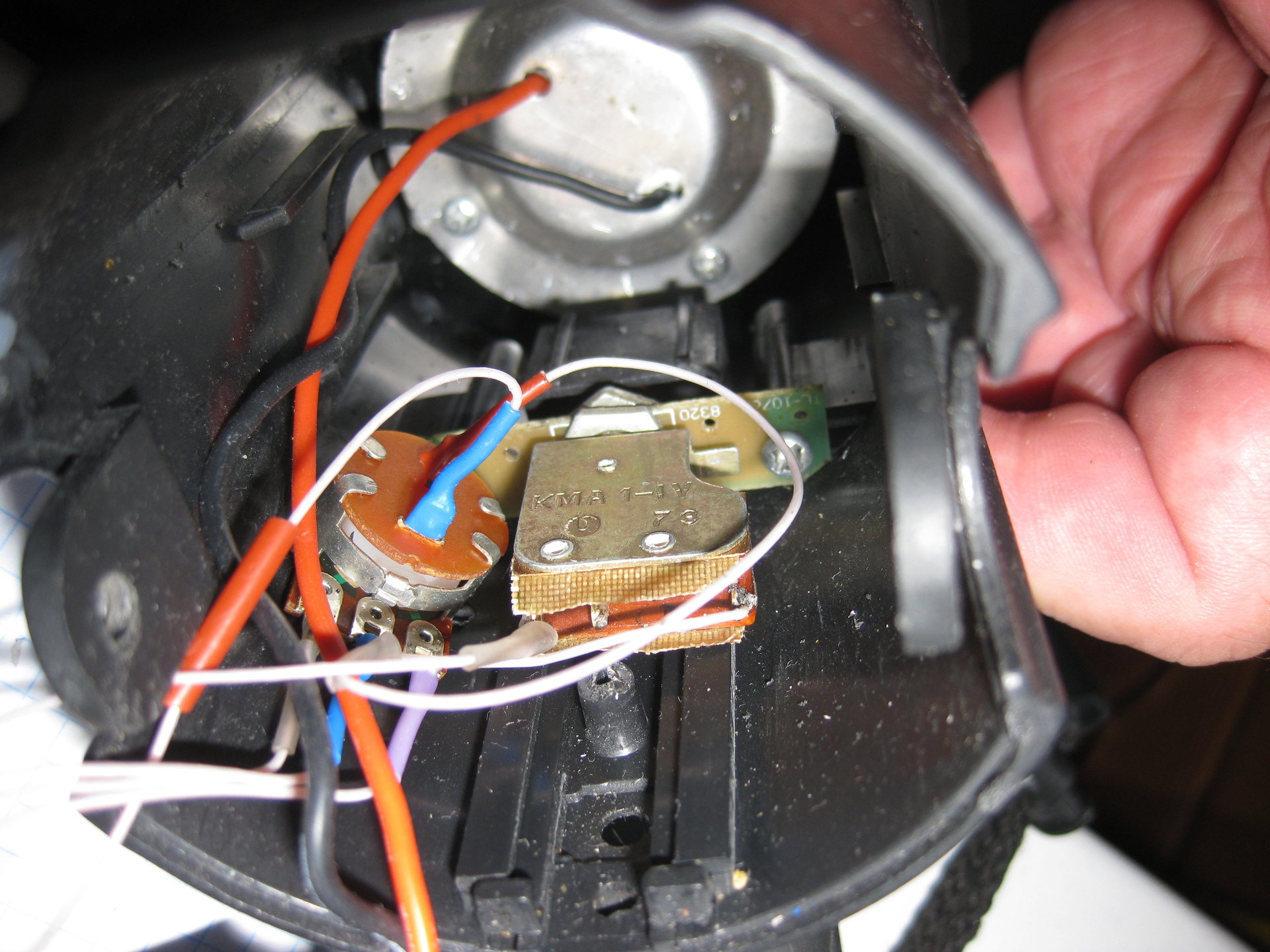
Fig. 8 The location of the variable resistor
When testing a flashlight with large currents (700-800 mA), poor contact appeared in the standard push-button switch. At small currents, the defect did not manifest itself, and at large currents the flashlight began to blink randomly.
I disassembled the flashlight, looked at the button, read the name, looked in the internet for the parameters and realized that this button is not suitable for switching such currents in principle, as it is designed for 100 mA.I had to take from the "stocks of the General Staff" button KMA 1-IV, released in 1973 in the USSR, capable of switching the current to 3A and put it in place of a regular misunderstanding.
In the process of testing, it turned out that in the maximum power mode, the aluminum radiator on which the LED is mounted heats up to about 60 degrees. Not surprisingly, the casing is completely enclosed, thick plastic, no heat sink. He considered, drilled holes in the housing so that the outside air cooled the radiator. It has become much better - now the heating is barely noticeable with long work in a few hours. I fixed the flashlight in a vice and inserted a mercury laboratory thermometer into the hole on top so that it touched the aluminum plate. After long work at full power (more than a couple of hours), the temperature stabilized at around 40 degrees C. In my opinion, it is quite satisfactory. In fig. 9 shows the holes in the lamp housing.

Fig.9 Holes in the case for cooling the radiator of the LED
The test lamp when operating at full power lasted more than 8 hours before shutting down when the voltage drops below 2.7 volts. This gives the total capacity of the four elements 18650 approximately 6000 mAh or 1500 mAh per element. Not bad for 10 year old items!
When discussing the project with my friend, a water tourist, the idea of analog indication of battery charge was born. Approximately the way it was done in the first wearable tape cassette recorders - there was a built-in dial gauge for the battery charge level and recording level. Then it was necessary to set the recording level manually! :)
Having before your eyes an indication of the balance of the charge, you can decide how to expend energy: to save the charge or you can turn on the full, not sparing.
Soon after, I accidentally hit the Quartz shop on the street. Buzheninova and, looking at the shop windows in anticipation of the completion of his wife’s affairs, came across such a wonderful analog indicator (Fig. 10):

Fig.10 Analogue Battery Level Indicator
Having estimated the dimensions, I decided that I would be able to insert it into the cover. On the back of the indicator rested on the board and had to slightly push out of the cover. The indicator is fixed with hot melt glue.
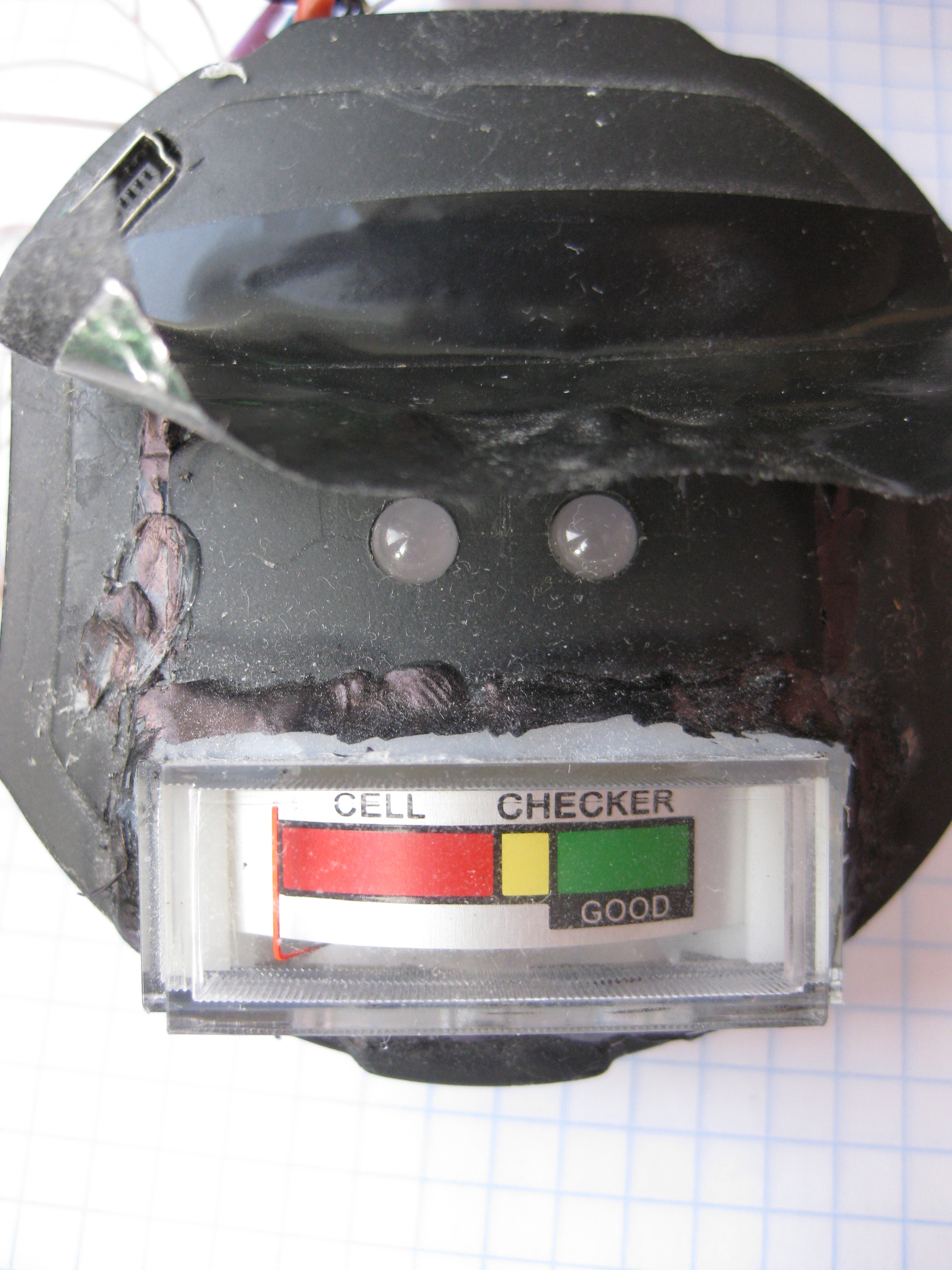
Fig.11 Analog battery level indicator in the lid The
red and green LEDs are located above the level indicator.
To control the indicator, I applied the second PWM channel in ATTINY13A. The calculation of the additional resistance and the PWM parameters was made so that the maximum deviation of the indicator arrow occurs when charging is connected, and the minimum - at a cutoff voltage of 2.7 volts. This is the digital equivalent of the “stretched scale”. Successfully it turned out that half of the battery discharge fell just on the yellow zone of the indicator.
To control the two LEDs (red and green), I still had one conclusion. I had to think a little :). The solution, see the schematic diagram, the elements of R5 - R7 and HL1 - HL2. A minor drawback of such a decision is the impossibility to turn off the LEDs altogether, even if you turn the ATTINY13A output into the third state - the LEDs will dimly glow.
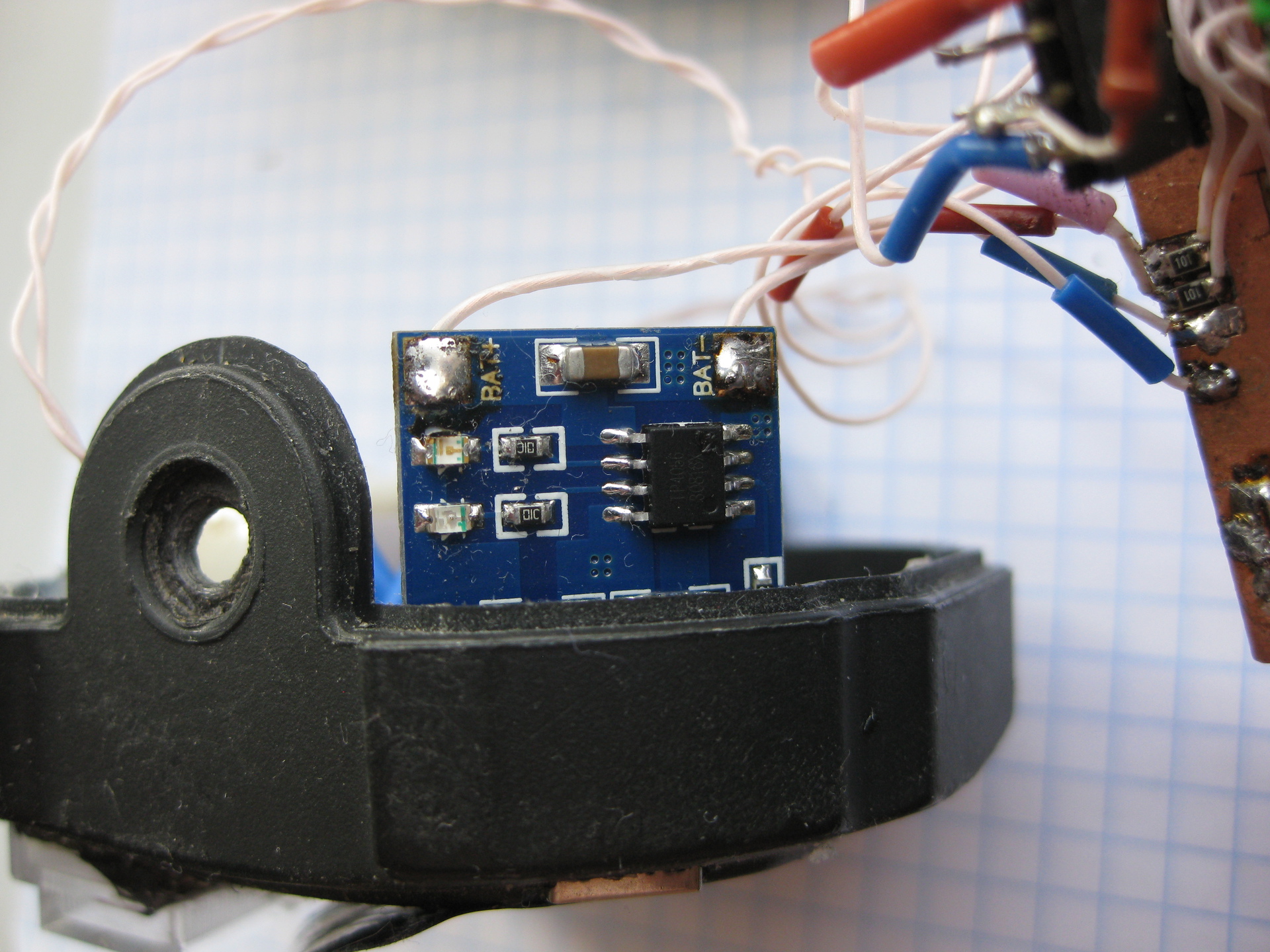
Fig. 12 Lithium battery charge board
The last thing I attached to the lamp is the charge board for lithium batteries (Fig. 12). I once bought a dilextstream, tempted by cheapness, but here it was used. The charge is current of the order of an amp and goes quite a long time - up to 10 hours. However, with a capacity of about 6000 mAh and a charge current of 1A, something like this should be. In the process of charging, the board shines with a blue diode, after it ends it turns green. In principle, it would be possible not to use this charge, but to disassemble the lamp and charge the elements in a separate external charger. I planned to do so at first, considering that 6000 mAh would be enough for the whole season. But laziness - the engine of progress - won and I built in the charger. Now it is enough to connect the miniUSB - USB cable from any 5v source. For charging purposes, charging from a network with a current of 1-2 A is better; a computer port with a current of 500 mA is worse;but also acceptable. I do not give references to the board, a search for the words "1a lithium board charger" will give you a sea of references. An additional bonus - the need to ensure easy disassembly of the flashlight to remove the battery pack has disappeared, this block can be fixed permanently.
The board is placed in the lamp cover, so that when the cover is closed, the board will enter the free space in the body of the lamp. The board is fixed with hot melt in place. MiniUSB connector available outside.
Control of the analog indicator was reduced to the calculation of the parameters of the PWM signal depending on the battery voltage.
The control program for ATTINY13A is small and I quote it directly here:
To obtain the desired frequency for dimming the LED, we had to change the timer divider to get the frequency of 586 Hz. In reality, the measured frequency of the PWM signal turned out to be 555 Hz, which is close enough to the calculated one, taking into account the accuracy of the built-in clock generator.
Double reading from the ADC is applied as by some assertions the first conversion after switching the support gives an inadequate result.
The rest of the code in my opinion is trivial and does not require explanation.
Tests showed that the assigned tasks were completed:
A lantern with continuous brightness adjustment from moonlite to full brightness was obtained, with a battery of about 6000 mache, which is enough for 11 hours of operation with full brightness and probably for a week in MOONLITE mode according to calculations.
The power source - lithium cells 18650 from the old battery from the laptop, found a second life.
The LED does not overheat, is in the correct thermal mode.
Dimming frequency of about 550 Hz provides a more or less safe mode for the eyes.
There are both an analog battery voltage indicator and a discrete indication on two different-colored LEDs.
The accuracy of the microcontroller's ADC is enough for surely shutting down the system at the critical voltage when the battery is discharged, the residual current consumption in the region of several milliamperes is not dangerous for a battery of this capacity, even if the user does not turn off the flashlight right away, but does so with a delay. In principle, you can change the program code so that at a critically low battery level, the LEDs also go out completely. Then the remaining current consumption of a microcontroller in a hundred microamperes will not be enough to cause appreciable damage to batteries.
Built-in charging allows you to use the lamp in standby mode with a permanently connected source, which ensures a constant 100% charge of the lamp, which is convenient at the dacha in case of accidental blackouts.
Project's budget.Parts cost 660 r for three sets, i.e. 220 r for one lantern. Lithium elements, etc. - is free. Analog measuring device cost 550 p, but it is not necessary. Time spent on the development and manufacture of course much more than it would take to simply replace the lead battery, but the pleasure of creativity is priceless :)
When buying items, I sought to unify. So, for example, if filter capacitors of 10-22 microfarads are required in the circuit, then it makes sense to buy not different pieces of a pair, but 10 of the largest nominal (22 microfarads in this case). The price for 10 pieces will be less than for single capacitors of different capacities, and an increase in the capacity of the filter capacitors will only have a positive effect on the functioning of the circuit.
A few years ago, when LED lights just started to appear in stores, I bought an LED digger at Okey. Large, with a pistol grip, conveniently lying in the hand, balanced. It had one 3-volt LED, a lead battery, and, as described, could stand on recharging without restrictions. It was what you need in the country. As we all know, in spite of the 21st century and the space ships plying the cosmos (C) - at a distance of more than 30 km from Moscow, the power supply becomes unreliable. Power networks disconnect electricity at any opportunity - in the rain, thunderstorm, heat and just like that. Usually on Saturday-Sunday for an hour or two, the electricity is cut off. Probably to train the population to survive in all conditions.
Therefore, the presence of a powerful, convenient flashlight, constantly charged and ready to go is practical.
')
Unfortunately, lead batteries have a limited service life of about three years, especially in standby mode with constant drip recharging. My flashlight was no exception, at some point I found that the battery does not hold a charge, but after a short time the voltage fell below the threshold of the LED.
Of course you could go to any store of radio components and buy a replacement battery. But a cursory study of the prices of such batteries did not arouse my enthusiasm. Having considered the question, I decided that in such a lamp it is reasonable to use lithium batteries of type 18650, remaining from the replacement of elements in the battery of the ancient (more than 10 years) Compaq NC6220 laptop, valuable by the presence of a hardware serial of the port.
Promer six old elements showed that four elements are quite suitable, one - so-so and one suitable only for emission. The four elements of 18650, assembled in a battery with parallel inclusion in size were like the old lead battery. I was surprised that the lithium cells from the old ten-year battery still have a capacity of about 1500 mAh with an initial 2200.
If we are already engaged in remaking a flashlight to a different type of battery, which automatically means changing the control board, then we can also dream it up. The body is large, you can place a lot. Personally, I had the idea that controlling the brightness of the flashlight would be the correct variable resistor. In fig. 1 shows a method for smoothly controlling the brightness of a LED lamp with a variable resistor.
Fig. 1. The method of smooth control of the brightness of the LED lamp variable resistor.
To replace the lead battery, I made a holder for four 18650 elements:
Fig. 2 Holder for four elements 18650
Elements 18650 are placed on a rectangular base of foiled fiberglass, in which Dremel cut 1.5 mm thick grooves for contact holders from springy bronze. All parts are connected by soldering, a 200 watt soldering iron made in USSR was used. The holders are soldered to the contacts from the solder, the thickness of the contacts is adjusted so that the 18650 held tightly with force. The battery pack is attached to the top of the case through two plastic insulation racks. Racks have a pin with an external M3 thread at one end and a recess with an internal M3 thread at the other end. The plastic nut is secured in the hole on the base of the battery assembly, and the entire assembly is screwed with an M3 bolt through the upper part of the housing. The design is folding, allows you to unscrew the two M3 screws and remove the entire battery pack. Elements 18650 are removed from the holders without the use of tools.
Directly from a lithium source, the LED can not be powered. The LED is powered by a stabilized current of 700 mA, while the voltage drop across it is about 3.7 volts. The lithium battery in a fully charged state gives a voltage of 4.2 volts, and in a discharged 2.7 volts. The current source for the LED must be able to work in the specified input voltage range (2.7 - 4.2 volts), providing a stable current of 700 mA in the LED. It is clear that this should be a pulse converter capable of operating in both voltage reduction and boost mode. Such converters are called BUCK-BOOST and there is some choice of chips in the market for building converters.
Since I decided to control the brightness of the diode with a variable resistor, I must convert the angle of the knob to a brightness control signal. Brightness control requires a PWM signal, the duty ratio (fill factor) of which will determine the integral brightness of the LED. Smoothly changing the duty cycle, you can smoothly change the brightness. At the same time will be reduced power consumption, prolonging the work of the lamp. In existing lamps, dimming modes are activated by successive button presses (usually the power button, sometimes a separate button). This way seems to me unergonomic, inconvenient. I am an adherent of the old-school analog control style with smoothly varying parameters with a round knob that can be rotated in both directions. Therefore, the best in this case is a variable resistor, the handle of which can be operated with the thumb. There are variable resistors with a switch that can additionally be used to switch the power of the flashlight. If you consistently turn on the nominal button and switch on the resistor, you will get a new quality - you can turn on the lamp by turning the resistor knob, while the brightness will gradually increase from the MOONLIGHT mode to the maximum. Or you can put the resistor knob to the desired position and turn the lamp off by pressing the button on the handle, each time getting the preset brightness. The position of the risks on the handle of the variable resistor uniquely determines the brightness of the lamp and can be set before switching on. With one button, you never know in which mode the lamp turns on. Yes, I read the descriptions of standard lamps and I know what they write there “the lamp should turn on in the same mode”. But all my lights of this type are included in a random mode.
It was interesting for me to make a converter that would be as economical as possible, would have the ability to dim the LED, would be able to switch off when the lithium battery voltage drops below 2.7 volts. Unfortunately, life is like this: “I want cheap, good and fast - of course, choose two of the three!”. I did not manage to find an inexpensive microcircuit that was at the same time economical, knew how to raise and lower the voltage and could dim from a variable resistor. As a result of reviewing the options, I chose the NCP5030 chip. It is inexpensive (~ 65 p), has a BUCK-BOOST mode and is quite economical, i.e. conversion losses are small.
Chip Parameters:
• Efficiency of 87% at a load current of 500 mA and an input voltage of 3.3 V
• Internal synchronous rectifier
• Maximum current per load - 900 mA
• 0.3 µA off current consumption
• Input voltage range 2.7 - 5.5 volts
• 200 mV feedback voltage to stabilize the output current
• Protection against overvoltage and overheating.
• Automatic transition between BUCK and BOOST modes
The conversion frequency is fixed and is 700 kHz. Such a fairly high conversion frequency on the one hand allows the use of inductance of a small nominal value, but on the other hand, it requires careful installation and the use of correct parts on the manual to prevent parasitic generation.
A built-in synchronous rectifier on field-effect transistors with a low channel resistance in the open state (voltage drop of about 0.1 volts) allows to significantly increase the efficiency compared to a rectifier even on Schottky diodes (voltage drop on a Schottky diode - 0.5 volts).
A very valuable feature of the NCP5030 chip is the automatic switching between the low and high modes of the input voltage. The battery voltage varies from 4.2 to 2.7 volts, and the LED should be about 3.7 volts. This means that as the battery discharges, you must first lower the input voltage, and then increase it. The NCP5030 automatically switches between the buck (buck) and boost (boost) modes, transparently to the user.
The wiring diagram of the NCP5030 is shown in fig. 3:
Fig. 3 Wiring diagram for the NCP5030
The disadvantage of the solution based on this chip is the presence of only digital dimming control - a discrete PWM signal must be sent to the CTRL input to control the brightness with a frequency of no more than 1000 Hz. Also, the chip does not have the means to control the battery voltage and shutdown when the voltage drops below the threshold of 2.7 volts.
When selecting parts, some difficulties are caused by the search for resistor R3. Its nominal is 220 milliohm or 0.22 ohm. The voltage from this resistor (directly proportional to the current through the LED) is used by the microcircuit to adjust the current of the LED. I did not find such a resistor for reasonable time and money, so I decided to make it out of several resistors connected in parallel with a larger nominal (1 ohm and so). In addition to the low price and availability of resistors of such ratings, it additionally becomes possible to easily adjust the LED current by installing different numbers of resistors in parallel. In my case, we got three resistors for 1 st and in parallel a 2 ohm resistor from two for 1 ohm. The total resistance of these resistors (R11, R13-R16) is 0.285 ohm, which at a feedback voltage of 200 millivolts gives a current in the LED of 700 mA.
Fig. 4 Pinout NCP5030
The NCP5030 chip is made in a 3-by-4-mm WFDN package with 12 pins and is obviously designed for mounting onto a printed circuit board. The distance between the terminals is 0.5 mm, the terminal thickness is 0.3 mm, plus it requires the connection of terminal 13 “under the abdomen” to the common terminal of the printed circuit board for the heat sink. In fig. Figure 4 shows the pinout of the NCP5030.
I consider it unreasonable to make printed circuit boards for individual products for a number of reasons, one of which is the difficulty of finalizing the product. If some idea came to mind, then at the stage when the printed circuit board is implemented, it is difficult to finish. It is possible to put additional jumpers or a pair of elements, but it is difficult to add a node.
Therefore, I consider optimal for myself the technology of manufacturing boards from double-sided foil fiberglass by cutting through the tracks with a clerical knife. Taking a fee of sufficient size, one can always, as new ideas emerge, complete the new part without touching the already made. The advantage of the method is the minimum time for the manufacture of such a board; no harmful reagents such as ferric chloride or other corrosive substances are needed for etching the board. This method of “advanced prototyping” proved its suitability - the devices made in this way lived in my house for about 30 years and were decommissioned due to obsolescence and replacement with more advanced modern devices.
However, it is difficult or even impossible to make a teething board for such a small chip. But you can cut the tracks of a reasonable size, which is easily done, for example, in increments of about 1 mm, install the chip upside down and unsolder it under a microscope. Terminal 13 should be soldered with 0.5 mm copper wire to the common wire of the board, the other terminals should be connected with a 0.12 mm wire, and the power terminals - with a pigtail of 3-4 such wires. The result is shown in Fig. five.
Fig. 5 Soldered NCP5030 Chip
Scheme earned immediately. It took only the adjustment of the LED current by soldering additional resistors in 1 ohm to get 700 mA.
The chip during long operation (hours) is barely warm, the finger feels weak heat and only. This means that the heat sink soldering solution of the copper wire is correct and ensures the normal operation of the heat. A thorough study of the waveforms of the oscilloscope showed perfect forms, exactly according to the manual.
For the full implementation of all the ideas put, it is necessary to realize something with a PWM signal that will control the LED brightness and monitor the battery voltage in order to turn off the system when the voltage drops below a critical level.
Analysis of possible solutions led to the conclusion that the cheapest (35 p.) And universal in terms of capabilities is the use of a simple microcontroller of the type ATTINY13A . This microcontroller does not require any strapping, except for the filter capacitor for power.
Key parameters ATTINY13A
• Supply voltage 1.8-5.5 volts
• 4 ADC channels with internal or external reference signal
• Current consumption less than 1 mA
• 6 programmable I / O lines (5, if you do not use the reset leg)
• 2 hardware PWM channels.
A certain role in the choice of this controller was played by the ability to program it in the Arduino environment and flash the program through Arduino.
The capabilities of the built-in ADC are quite enough for removing the position of the variable resistor's engine and measuring the battery voltage. The microcontroller includes its own reference voltage source (1.1 volts), which makes it possible to measure the battery voltage. You can programmatically include either an internal reference source (if you need to measure the battery voltage), or an external one - if you need to measure the position of the slider of the resistor. There are also a couple of free outputs that I used to control two LEDs of different colors and an analog measuring head. Two LEDs allow you to evaluate the battery status at a glance: green means more than half the charge, red means less than half the charge.
For programming, it is required to disconnect 4 outputs from the circuit and connect them from to the programmer. Pulling the microcontroller for programming from the cot is inconvenient, so I installed 6 pin connectors on the board (4 signal + 1 power + 1 common). They are two pins on which a standard jumper is worn. If the jumper is in place, the circuit is functioning normally. For programming, jumpers need to be removed and connected to the free pins of the programmer pin. In programming mode, the power to the ATTINY13A is supplied from the programmer.
There are enough resources on the ATTINY13A programming topic through the Arduino board and creating programs in the Arduino IDE. I used these sources 1 and 2 .
From the subtleties - you need a file boards.txt, in which the parameters that control the clocking of the processor and the settings of the internal divider are correctly defined.
Without this, the PWM signal frequency will be incorrect and the software delays will not be processed correctly.
I also had to correct the name ATTINY13 on ATTINY13A, the programmer at the beginning of the process interrogates the microcontroller and gives an error if it cannot find a section with exactly that name.
The circuit diagram of the flashlight is shown in fig. 6
Fig. 6 Schematic diagram of the lamp
The battery voltage is supplied to the ADC2 ATTINY13A input through a resistor divider. When measuring the battery voltage, the internal reference source for the 1.1-volt ADC is programmatically turned on and therefore the maximum allowable voltage at the input should not exceed 1.1 volts. Proceeding from this limitation, the nominal values of the divider R1-R2 are calculated with a certain margin.
The voltage from the slider of the variable resistor is fed to the ADC3 input and when reading this input an external support is used - the battery voltage. In this mode, the data from the ADC is proportional to the rotation angle of the potentiometer slider and does not depend on the battery voltage. This data varies in the range of 0-1023.
In fig. 7 shows the flashlight board in its entirety with all the details.
Fig. 7 Lantern charge entirely
Considering the issue of analog LED brightness control, I decided that since the organs of hearing and human vision perceive the signal logarithmically, it would be correct to use a resistor with the inverse logarithmic dependence of the output signal on the angle of rotation — so that it seemed that the signal (LED brightness) changes smoothly and evenly the entire range of rotation of the handle. When buying such a resistor, it is necessary to take into account the peculiarities of marking domestic and foreign resistors - domestic ones are labeled as type "B", and foreign ones - as type "A".
Unfortunately, I could not buy a small-sized variable resistor with anti-logarithmic (sonic) dependency and with a switch. Therefore, I bought a resistor with a linear dependence of a small size and with a switch and applied a hardware hack (resistor R4 on a circuit diagram), long known to hams. This method is described for example, here .
Place for the installation of a resistor in the lamp housing is chosen experimentally - so that it is convenient to turn it with your thumb and so that it does not interfere with other components inside (see. Fig. 8)
Fig. 8 The location of the variable resistor
When testing a flashlight with large currents (700-800 mA), poor contact appeared in the standard push-button switch. At small currents, the defect did not manifest itself, and at large currents the flashlight began to blink randomly.
I disassembled the flashlight, looked at the button, read the name, looked in the internet for the parameters and realized that this button is not suitable for switching such currents in principle, as it is designed for 100 mA.I had to take from the "stocks of the General Staff" button KMA 1-IV, released in 1973 in the USSR, capable of switching the current to 3A and put it in place of a regular misunderstanding.
In the process of testing, it turned out that in the maximum power mode, the aluminum radiator on which the LED is mounted heats up to about 60 degrees. Not surprisingly, the casing is completely enclosed, thick plastic, no heat sink. He considered, drilled holes in the housing so that the outside air cooled the radiator. It has become much better - now the heating is barely noticeable with long work in a few hours. I fixed the flashlight in a vice and inserted a mercury laboratory thermometer into the hole on top so that it touched the aluminum plate. After long work at full power (more than a couple of hours), the temperature stabilized at around 40 degrees C. In my opinion, it is quite satisfactory. In fig. 9 shows the holes in the lamp housing.
Fig.9 Holes in the case for cooling the radiator of the LED
The test lamp when operating at full power lasted more than 8 hours before shutting down when the voltage drops below 2.7 volts. This gives the total capacity of the four elements 18650 approximately 6000 mAh or 1500 mAh per element. Not bad for 10 year old items!
When discussing the project with my friend, a water tourist, the idea of analog indication of battery charge was born. Approximately the way it was done in the first wearable tape cassette recorders - there was a built-in dial gauge for the battery charge level and recording level. Then it was necessary to set the recording level manually! :)
Having before your eyes an indication of the balance of the charge, you can decide how to expend energy: to save the charge or you can turn on the full, not sparing.
Soon after, I accidentally hit the Quartz shop on the street. Buzheninova and, looking at the shop windows in anticipation of the completion of his wife’s affairs, came across such a wonderful analog indicator (Fig. 10):
Fig.10 Analogue Battery Level Indicator
Having estimated the dimensions, I decided that I would be able to insert it into the cover. On the back of the indicator rested on the board and had to slightly push out of the cover. The indicator is fixed with hot melt glue.
Fig.11 Analog battery level indicator in the lid The
red and green LEDs are located above the level indicator.
To control the indicator, I applied the second PWM channel in ATTINY13A. The calculation of the additional resistance and the PWM parameters was made so that the maximum deviation of the indicator arrow occurs when charging is connected, and the minimum - at a cutoff voltage of 2.7 volts. This is the digital equivalent of the “stretched scale”. Successfully it turned out that half of the battery discharge fell just on the yellow zone of the indicator.
To control the two LEDs (red and green), I still had one conclusion. I had to think a little :). The solution, see the schematic diagram, the elements of R5 - R7 and HL1 - HL2. A minor drawback of such a decision is the impossibility to turn off the LEDs altogether, even if you turn the ATTINY13A output into the third state - the LEDs will dimly glow.
Fig. 12 Lithium battery charge board
The last thing I attached to the lamp is the charge board for lithium batteries (Fig. 12). I once bought a dilextstream, tempted by cheapness, but here it was used. The charge is current of the order of an amp and goes quite a long time - up to 10 hours. However, with a capacity of about 6000 mAh and a charge current of 1A, something like this should be. In the process of charging, the board shines with a blue diode, after it ends it turns green. In principle, it would be possible not to use this charge, but to disassemble the lamp and charge the elements in a separate external charger. I planned to do so at first, considering that 6000 mAh would be enough for the whole season. But laziness - the engine of progress - won and I built in the charger. Now it is enough to connect the miniUSB - USB cable from any 5v source. For charging purposes, charging from a network with a current of 1-2 A is better; a computer port with a current of 500 mA is worse;but also acceptable. I do not give references to the board, a search for the words "1a lithium board charger" will give you a sea of references. An additional bonus - the need to ensure easy disassembly of the flashlight to remove the battery pack has disappeared, this block can be fixed permanently.
The board is placed in the lamp cover, so that when the cover is closed, the board will enter the free space in the body of the lamp. The board is fixed with hot melt in place. MiniUSB connector available outside.
Control of the analog indicator was reduced to the calculation of the parameters of the PWM signal depending on the battery voltage.
The control program for ATTINY13A is small and I quote it directly here:
Management software for ATTINY13A
void setup () {
pinMode(0, OUTPUT);
pinMode(1, OUTPUT);
pinMode(2, OUTPUT);
/ *
Setting Divisor Frequency PWM on 9.6, 4.8, 1.2 MHz CPU
0x01 divisor is 1 37500, 18750, 4687 Hz
0x02 divisor is 8 4687, 2344, 586 Hz
0x03 divisor is 64 586, 293, 73 Hz
0x04 divisor is 256 146, 73, 18 Hz
0x05 divisor is 1024 36, 17, 5 Hz
* /
TCCR0B = TCCR0B & 0b11111000 | 0x02; // 0x02 divisor is 8 586 Hz
}
void loop(void) {
analogReference(INTERNAL);
int batt=analogRead(3);
delay(25);
batt=analogRead(3);
analogReference(EXTERNAL);
int resistor=analogRead(2);
delay(25);
resistor=analogRead(2);
int r=(resistor*32);
r=r/147+33;
if (r > 255) {r=255;} //led starts to light at 13.8% PWM
if (batt > 440) {
analogWrite(0, r);
}
else
{
analogWrite(0, 0);
}
if(batt<560) {
digitalWrite(2, HIGH);
}
else
{
digitalWrite(2, LOW);
}
if(batt<440) {batt=440;}
if(batt>(440+255)) {batt=440+255;}
analogWrite(1, batt-440);
}
To obtain the desired frequency for dimming the LED, we had to change the timer divider to get the frequency of 586 Hz. In reality, the measured frequency of the PWM signal turned out to be 555 Hz, which is close enough to the calculated one, taking into account the accuracy of the built-in clock generator.
Double reading from the ADC is applied as by some assertions the first conversion after switching the support gives an inadequate result.
The rest of the code in my opinion is trivial and does not require explanation.
Tests showed that the assigned tasks were completed:
A lantern with continuous brightness adjustment from moonlite to full brightness was obtained, with a battery of about 6000 mache, which is enough for 11 hours of operation with full brightness and probably for a week in MOONLITE mode according to calculations.
The power source - lithium cells 18650 from the old battery from the laptop, found a second life.
The LED does not overheat, is in the correct thermal mode.
Dimming frequency of about 550 Hz provides a more or less safe mode for the eyes.
There are both an analog battery voltage indicator and a discrete indication on two different-colored LEDs.
The accuracy of the microcontroller's ADC is enough for surely shutting down the system at the critical voltage when the battery is discharged, the residual current consumption in the region of several milliamperes is not dangerous for a battery of this capacity, even if the user does not turn off the flashlight right away, but does so with a delay. In principle, you can change the program code so that at a critically low battery level, the LEDs also go out completely. Then the remaining current consumption of a microcontroller in a hundred microamperes will not be enough to cause appreciable damage to batteries.
Built-in charging allows you to use the lamp in standby mode with a permanently connected source, which ensures a constant 100% charge of the lamp, which is convenient at the dacha in case of accidental blackouts.
Project's budget.Parts cost 660 r for three sets, i.e. 220 r for one lantern. Lithium elements, etc. - is free. Analog measuring device cost 550 p, but it is not necessary. Time spent on the development and manufacture of course much more than it would take to simply replace the lead battery, but the pleasure of creativity is priceless :)
When buying items, I sought to unify. So, for example, if filter capacitors of 10-22 microfarads are required in the circuit, then it makes sense to buy not different pieces of a pair, but 10 of the largest nominal (22 microfarads in this case). The price for 10 pieces will be less than for single capacitors of different capacities, and an increase in the capacity of the filter capacitors will only have a positive effect on the functioning of the circuit.
Source: https://habr.com/ru/post/368137/
All Articles