About the development of heads for 3D FDM printers. Part 3
Continuation of parts 1 and 2 .
In the previous 2 parts, we considered the theoretical aspects of the calculation of the heads for FDM printers and the calculation of the new head. Now, let's take a closer look at the procedure for obtaining data, what is considered, and what are the important performance indicators of the system, let's compare the new and previous heads. We solve the problem revealed. Let's talk that you can still change / add.
Fig. 24 So, the head is made.
Fig.25 And here are replaceable nozzles for it, left from the previous version of the head.
Fig.26 Original parts
Fig.27 Already welded, heater and thermocouple.
In zone A , we see the incoming cold filament. Its properties have not yet changed from heating, therefore its resistance to movement is determined by friction against the walls. It can be well reduced by using a Teflon liner - a tube, since Teflon at not too high temperatures, in conditions where it has nowhere to flow (just the liner), works well, and the sliding friction on it is very low.
Chapter 3
Now you need to check the head and draw conclusions. Since the purpose of the development was to get a quick and easy head, I check it only for speed, resistance to traffic jams, ease of changing nozzles. Therefore, I check not in the printer, but in a separate extruder fixed on the vertical bar. There are a number of reasons for this: - Generally, at such high speeds, which are obtained when working on a number of nozzle diameters, I don’t know which printer will work. This is a matter of further development. And just for the convenience of experiences.
So how best to measure head performance? A significant problem is the apparent dependence of the performance of the nozzle on the force of feeding the line by an extruder, and it depends on the clamping force on the hobbolt. I use a rather radical hobbolt with a "diamond" notch. It works very effectively, although it tends to tear ABS into small crumbs with even a slight slip. Clamping springs - powerful.
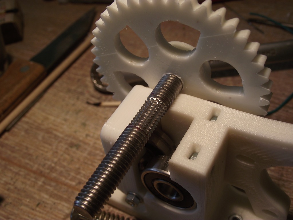
Fig.28 Here I have such an extruder and a hobbolt with a "diamond" notch.
3.1. Experience and calculations. The measurement of the maximum extrusion speed for the relevant conditions (such as a nozzle, plastic, temperature) is performed as follows: - I heat the head to the working temperature, then I give a small feed at medium speed to remove the void in the head and squeeze out a little fishing line. Quickly enter the length of the extruded filament and the speed of extrusion, I launch for execution. At the end of the cut off the squeezed fishing line immediately. I do a retract at 30mm at medium speed - I'm not sure that this is necessary, but it works stably for me. Reproducibility is good. We weigh the line, I have scales with an accuracy of 10 mg. In breaks I turn off the heat - the head warms up quickly. The length specified is usually 30 cm with a diameter of 3 mm, and ABS plastic, at 100% extrusion gives 2.485 g. If I want to save money, you can take less on already known sites, for example - 150mm - the accuracy is worse. Such a considerable piece is also explained by the fact that there is an error in post-extrusion from the previous extrusion. Those. while I enter the data manages to extrude a small piece of fishing line. But since the previous extrusion was at medium speed - the magnitude of the error is very small. Negligible.
Determination of 100% extrusion value. In the ideal case, we remove the head, mark a filament with something, give a command to feed, for example, a 50 cm filament. We measure how much really advanced through the extruder. Weigh this piece. Its weight will be the weight of 100% of the filing. Measure exactly its diameter - handy. Do not forget that maybe the feed rate of the extruder is not equal to one. For example, you set the feed 50 cm, and it was 52 cm.
Calculation of the coefficient of slippage (more correctly non-slip)
This is the ratio of the weight of what was extruded, to what should have been - to 100% extrusion, multiplied by 100. By the way, a very effective and accurate way to determine the pressure limit. At 80%, the slippage is 1/5 of the hobbol's entire path and the teeth do not begin to crumble. If the coefficient drops noticeably below 80%, then the stability of the results due to the violation of the contact of the hobbolt with the filament is not obtained. This point is as follows: - we make a series of experiments with a feed of 150 or 300 mm and speed, for example 90,120,140,160 mm / min. By the extruded mass in each case, we consider the percentage of slippage. Experience with the feed rate at which the coefficient of slippage will be about 80% and will be experience with the maximum speed of extrusion. It will have to be calculated by dividing the extruded mass by the extrusion time in seconds (a segment of length — with speed — in seconds). It turns out performance in mg / s. If you divide it by the filament density, you will get a volume productivity of mm ³ / s, if you divide it by the nozzle section area, you will get a linear velocity at the nozzle exit in mm / s. Please note that at a point close to 80%, productivity growth stops! That is, according to my data, quite accurate mark. I can recommend the measurement of the slip coefficient as a characteristic of the operation of your extruder. And if the head is OK, and the performance is less than it should be, and the percentage drops sharply below 80%, then you need to deal with the extruder.
Blow up fishing line. If you try to measure the extruded fishing line in length, you will see that in any case it will be slightly less than theoretical (meaning when the fishing line is squeezed into the air). This is due to the expansion of the fishing line at the exit of the nozzle, due to friction of the outer layers of the nozzle wall. The inner layers of the melt move faster and inflate the outer layers. In some extreme cases (determining the maximum melting rate of the filament), I have observed an increase in diameter of 3-3.5 times! But this should not worry you. When printing, first of all, the conditions are: - nozzle diameter, the extrusion speed is not so hard, because the degree of blow-up is small. In this case, the head is very close to the surface of the substrate. On it, such effects should be extinguished. It may be necessary to change the layer thickness (reduce) and / or increase the speed of the head slightly (without increasing extrusion). This is the case if uneven protruding irregularities will be visible at the edges.
Determination of the maximum melting rate of the filament.
In this case, I used a nozzle with a diameter of 0.9 mm. Its own resistance, with equal performance, is 80 times less than for a nozzle with a diameter of 0.3 mm. Why is that? Yes, the resistance is proportional to the square of the diameter of the hole. But in order to equalize the volumetric flow rate, in a narrower nozzle, the linear velocity must also be larger, proportional to the square of the diameter ratio. Thus, in the case of a nozzle 0.9mm resistance can be neglected. It remains only to take into account the section of the filament, which is already in the head, and which has completely melted. His weight in my case, theoretically 320mg, almost 270-300. How to understand? Just when extruded, the pre-melted plastic is clearly visible. It flows like a thin stream. Then immediately begins to climb a thick, uneven sausage. Irregularities are partially unmelted pieces, at times overlapping the nozzle and creating pressure drops, and hence thicknesses.
3.2. Comparison of the calculated and the previous heads.
Results for a calculated and made Type 4.2 head at a temperature of about 263º - the temperature was taken with a thermocouple, and then checked with an electronic kitchen thermometer, stuck into the melt instead of an inverted nozzle (per rectum).
- for the nozzle 0,2 mm, 10,2 mm ³ / s, 86,1%, which corresponds to the speed at the nozzle exit 324 mm / s
- for nozzle 0.3mm, 22.3 mm³ / s, 84.9%, which corresponds to a speed of 315 mm / s.
- for nozzle 0.4 mm, 29.1, 85.3% mm ³ / s which corresponds to a speed of 231 mm / s
-for nozzle 0.9mm, 40.1 mm³ / s, 84.9%, which corresponds to a speed of 63 mm / s
In the case of raising the temperature of the heater by another 20º, for a 0.3mm nozzle, the capacity grew by another 15%, to 27.5 mm³ / s, 80.5%, which corresponds to a speed of 388mm / s.
Probably for other diameters as well. Note the unexpectedly large drop in performance for a 0.2 mm nozzle. At the same time, attempts to exceed the speed often ended in blocking. The formation of traffic jams. Consider in more detail below.
Compare with the data for the head of the previous type - Type 4.1. She had problems with a thermal barrier and she was unstable, sometimes slowing down, she had quite a lot of resistance to pushing the rod, due to the design and long working area - up to 54mm, with a thermal barrier in a hot brass radiator! Heat flow was too high. We'll see.
- for the nozzle 0,2 mm to eliminate some problems 12.37 mm ³ / s, 78.5%, which corresponds to the speed at the nozzle exit 393 mm / s
- for the nozzle 0.3mm to eliminate, 21.4 mm³ / s, 81.3%, which corresponds to a speed of 302 mm / s.
-for nozzle 0.2 / 0.24 mm 16.2 mm³ / s, 77.3%, which corresponds to a speed of 516/358 mm / s
- for nozzle 0.3 mm 21.99 mm³ / s, 83.7%, which corresponds to a speed of 311 mm / s
-for nozzle 0.9mm 46 mm³ / s, 83.7%, which corresponds to a speed of 72 mm / s.
A strange nozzle of 0.2 / 0.24 mm - I cleaned it, and I suspected that I had expanded somewhat. The diameter of the opening is Meryl along the outgoing line, at low feed and at T = 245º. It turned out 0,23-0,24. It is true then, when I made a new nozzle with a diameter of 0.2 mm and measured the line from it, under the same conditions, it turned out 0.22-0.23. A suspected nozzle redid under 0.4mm. So in case the diameter of the nozzle was close to 0.2 mm, the flow rate to 500 mm / s! If 0.24 - pessimistic - 358mm / s. But the performance is much higher than in the new head. Compare: 10.2 and 16.2 mm³ / s.
For a 0.3mm nozzle, 22.3 and 22 mm³ / s - here the new one is slightly faster, by 1.5%.
For the nozzle 0.9mm 40.1 and 46.1 mm³ / s - here the old one is faster, by 15%. This is just clear, the length of the working area is almost twice as large, the heating area is larger, therefore the rate of melting of the filament should be higher.
3.3. Analysis of performance problems on the nozzle 0,2 mm.
Due to the successful design (I explain this with the PTFE liner everywhere except in the hot zone), I easily removed the cork. Take a look.
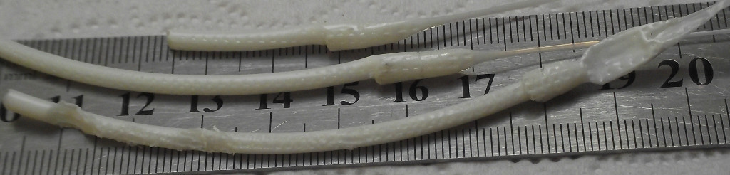
Fig.29. Cork when testing on a nozzle with a diameter of 0.2 mm.
On the bottom piece you can see the place gnawed by the hobbol during slipping. The enlarged part of the cork is 8-10 mm in length, and in diameter is exactly 4.2 mm. This is the inner diameter of the Teflon liner. If you look closer, on the bottom piece, you can clearly see pushing back the soft mass. That is, she turned around and prodded back, even cracking, that is, she was not too plastic. On the middle piece is clearly visible cylindrical strip - dent. This is the section between the steel liner and teflon liner. From the edge you can see the compression at the entrance to the head. Wide flat inflation at the end of the lower piece is a sign of good filament stretching from the head. The melt came out stocking uniformly and was compressed by an extruder.
- Conclusion: The softening of the filament began noticeably above the planned place, it means that too much heat is supplied to the steel liner ring and does not have time to move away from it. Let's see a suspicious plot drawing.
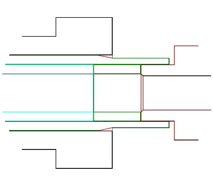
Fig.30
I highlighted in red the place that I machined with a hollow, not a neat step. Unusually sharpen such stainless steel 304L, an unusual carbide cutter, and did not pay attention (although I saw my joint about a millimeter and a half - I thought it did not matter). And here's the result: -The heat flow from the head (dark red) goes through the thermal barrier tube and the liner-ring, but, having entered the hot radiator, it cannot give heat to it due to the air gap. The ring insert is cooled only by a small part of its surface and is overheated. In fact, this is clearly seen in Figs 27 and 26. Part of stainless steel. But why, then, does it have any effect in the case of a nozzle with a diameter of 0.3 mm or more? Because, at the site of the liner ring, the heat transfer from the walls to the filament is quite high - the heat insulator-Teflon layer does not interfere and at a flow rate higher than some, the excess heat is carried away by the flow of the filament. And why the cork is not formed when idle? After all, nothing at all is carried away. - Still, a hot radiator works and removes heat, just not enough. With a simple mechanical load on the filament there is no and it does not swell, not where necessary. So in order to achieve a speed of 500 mm / s on a diameter of 0.2 mm, it is necessary to eliminate it or redo the head. For my theoretical research, it does not matter much.
3.4 What can be done to reliably correct the observed error.
- We slightly increase the area of thermal contact of the liner in the area of the radiator.
- In this ring, in the area of the thermal barrier, we make a small groove. Make calculation of thermal flows!
- We reduce the length of the thermal barrier to 2 mm.
- It would be nice to put the thermistor in a hot radiator and program Arduino to control its rotation, maintaining the temperature at 90-110º, this should be clarified by location.
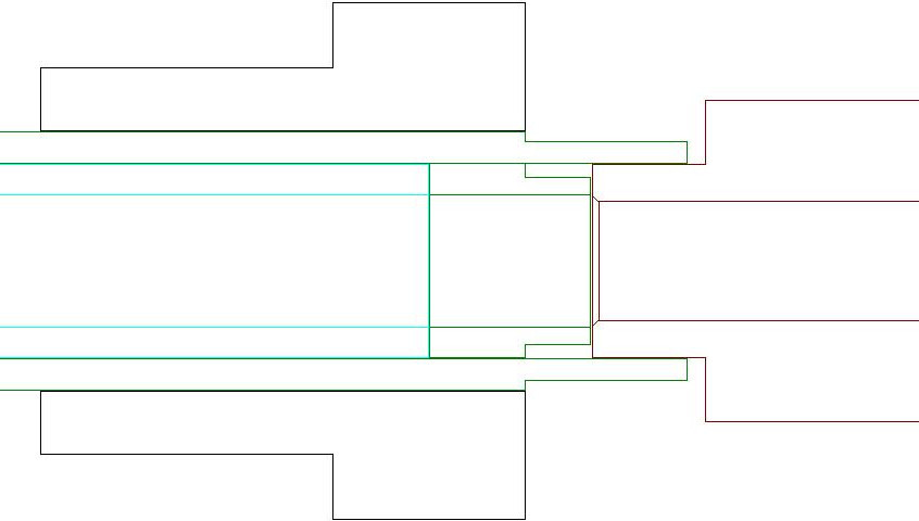
Fig.31 Corrected version.
That's all for now. Thanks for attention. Success in creative work.
In the previous 2 parts, we considered the theoretical aspects of the calculation of the heads for FDM printers and the calculation of the new head. Now, let's take a closer look at the procedure for obtaining data, what is considered, and what are the important performance indicators of the system, let's compare the new and previous heads. We solve the problem revealed. Let's talk that you can still change / add.
Fig. 24 So, the head is made.
Fig.25 And here are replaceable nozzles for it, left from the previous version of the head.
Fig.26 Original parts
Fig.27 Already welded, heater and thermocouple.
In zone A , we see the incoming cold filament. Its properties have not yet changed from heating, therefore its resistance to movement is determined by friction against the walls. It can be well reduced by using a Teflon liner - a tube, since Teflon at not too high temperatures, in conditions where it has nowhere to flow (just the liner), works well, and the sliding friction on it is very low.
Chapter 3
Now you need to check the head and draw conclusions. Since the purpose of the development was to get a quick and easy head, I check it only for speed, resistance to traffic jams, ease of changing nozzles. Therefore, I check not in the printer, but in a separate extruder fixed on the vertical bar. There are a number of reasons for this: - Generally, at such high speeds, which are obtained when working on a number of nozzle diameters, I don’t know which printer will work. This is a matter of further development. And just for the convenience of experiences.
So how best to measure head performance? A significant problem is the apparent dependence of the performance of the nozzle on the force of feeding the line by an extruder, and it depends on the clamping force on the hobbolt. I use a rather radical hobbolt with a "diamond" notch. It works very effectively, although it tends to tear ABS into small crumbs with even a slight slip. Clamping springs - powerful.
Fig.28 Here I have such an extruder and a hobbolt with a "diamond" notch.
3.1. Experience and calculations. The measurement of the maximum extrusion speed for the relevant conditions (such as a nozzle, plastic, temperature) is performed as follows: - I heat the head to the working temperature, then I give a small feed at medium speed to remove the void in the head and squeeze out a little fishing line. Quickly enter the length of the extruded filament and the speed of extrusion, I launch for execution. At the end of the cut off the squeezed fishing line immediately. I do a retract at 30mm at medium speed - I'm not sure that this is necessary, but it works stably for me. Reproducibility is good. We weigh the line, I have scales with an accuracy of 10 mg. In breaks I turn off the heat - the head warms up quickly. The length specified is usually 30 cm with a diameter of 3 mm, and ABS plastic, at 100% extrusion gives 2.485 g. If I want to save money, you can take less on already known sites, for example - 150mm - the accuracy is worse. Such a considerable piece is also explained by the fact that there is an error in post-extrusion from the previous extrusion. Those. while I enter the data manages to extrude a small piece of fishing line. But since the previous extrusion was at medium speed - the magnitude of the error is very small. Negligible.
Determination of 100% extrusion value. In the ideal case, we remove the head, mark a filament with something, give a command to feed, for example, a 50 cm filament. We measure how much really advanced through the extruder. Weigh this piece. Its weight will be the weight of 100% of the filing. Measure exactly its diameter - handy. Do not forget that maybe the feed rate of the extruder is not equal to one. For example, you set the feed 50 cm, and it was 52 cm.
Calculation of the coefficient of slippage (more correctly non-slip)
This is the ratio of the weight of what was extruded, to what should have been - to 100% extrusion, multiplied by 100. By the way, a very effective and accurate way to determine the pressure limit. At 80%, the slippage is 1/5 of the hobbol's entire path and the teeth do not begin to crumble. If the coefficient drops noticeably below 80%, then the stability of the results due to the violation of the contact of the hobbolt with the filament is not obtained. This point is as follows: - we make a series of experiments with a feed of 150 or 300 mm and speed, for example 90,120,140,160 mm / min. By the extruded mass in each case, we consider the percentage of slippage. Experience with the feed rate at which the coefficient of slippage will be about 80% and will be experience with the maximum speed of extrusion. It will have to be calculated by dividing the extruded mass by the extrusion time in seconds (a segment of length — with speed — in seconds). It turns out performance in mg / s. If you divide it by the filament density, you will get a volume productivity of mm ³ / s, if you divide it by the nozzle section area, you will get a linear velocity at the nozzle exit in mm / s. Please note that at a point close to 80%, productivity growth stops! That is, according to my data, quite accurate mark. I can recommend the measurement of the slip coefficient as a characteristic of the operation of your extruder. And if the head is OK, and the performance is less than it should be, and the percentage drops sharply below 80%, then you need to deal with the extruder.
Blow up fishing line. If you try to measure the extruded fishing line in length, you will see that in any case it will be slightly less than theoretical (meaning when the fishing line is squeezed into the air). This is due to the expansion of the fishing line at the exit of the nozzle, due to friction of the outer layers of the nozzle wall. The inner layers of the melt move faster and inflate the outer layers. In some extreme cases (determining the maximum melting rate of the filament), I have observed an increase in diameter of 3-3.5 times! But this should not worry you. When printing, first of all, the conditions are: - nozzle diameter, the extrusion speed is not so hard, because the degree of blow-up is small. In this case, the head is very close to the surface of the substrate. On it, such effects should be extinguished. It may be necessary to change the layer thickness (reduce) and / or increase the speed of the head slightly (without increasing extrusion). This is the case if uneven protruding irregularities will be visible at the edges.
Determination of the maximum melting rate of the filament.
In this case, I used a nozzle with a diameter of 0.9 mm. Its own resistance, with equal performance, is 80 times less than for a nozzle with a diameter of 0.3 mm. Why is that? Yes, the resistance is proportional to the square of the diameter of the hole. But in order to equalize the volumetric flow rate, in a narrower nozzle, the linear velocity must also be larger, proportional to the square of the diameter ratio. Thus, in the case of a nozzle 0.9mm resistance can be neglected. It remains only to take into account the section of the filament, which is already in the head, and which has completely melted. His weight in my case, theoretically 320mg, almost 270-300. How to understand? Just when extruded, the pre-melted plastic is clearly visible. It flows like a thin stream. Then immediately begins to climb a thick, uneven sausage. Irregularities are partially unmelted pieces, at times overlapping the nozzle and creating pressure drops, and hence thicknesses.
3.2. Comparison of the calculated and the previous heads.
Results for a calculated and made Type 4.2 head at a temperature of about 263º - the temperature was taken with a thermocouple, and then checked with an electronic kitchen thermometer, stuck into the melt instead of an inverted nozzle (per rectum).
- for the nozzle 0,2 mm, 10,2 mm ³ / s, 86,1%, which corresponds to the speed at the nozzle exit 324 mm / s
- for nozzle 0.3mm, 22.3 mm³ / s, 84.9%, which corresponds to a speed of 315 mm / s.
- for nozzle 0.4 mm, 29.1, 85.3% mm ³ / s which corresponds to a speed of 231 mm / s
-for nozzle 0.9mm, 40.1 mm³ / s, 84.9%, which corresponds to a speed of 63 mm / s
In the case of raising the temperature of the heater by another 20º, for a 0.3mm nozzle, the capacity grew by another 15%, to 27.5 mm³ / s, 80.5%, which corresponds to a speed of 388mm / s.
Probably for other diameters as well. Note the unexpectedly large drop in performance for a 0.2 mm nozzle. At the same time, attempts to exceed the speed often ended in blocking. The formation of traffic jams. Consider in more detail below.
Compare with the data for the head of the previous type - Type 4.1. She had problems with a thermal barrier and she was unstable, sometimes slowing down, she had quite a lot of resistance to pushing the rod, due to the design and long working area - up to 54mm, with a thermal barrier in a hot brass radiator! Heat flow was too high. We'll see.
- for the nozzle 0,2 mm to eliminate some problems 12.37 mm ³ / s, 78.5%, which corresponds to the speed at the nozzle exit 393 mm / s
- for the nozzle 0.3mm to eliminate, 21.4 mm³ / s, 81.3%, which corresponds to a speed of 302 mm / s.
-for nozzle 0.2 / 0.24 mm 16.2 mm³ / s, 77.3%, which corresponds to a speed of 516/358 mm / s
- for nozzle 0.3 mm 21.99 mm³ / s, 83.7%, which corresponds to a speed of 311 mm / s
-for nozzle 0.9mm 46 mm³ / s, 83.7%, which corresponds to a speed of 72 mm / s.
A strange nozzle of 0.2 / 0.24 mm - I cleaned it, and I suspected that I had expanded somewhat. The diameter of the opening is Meryl along the outgoing line, at low feed and at T = 245º. It turned out 0,23-0,24. It is true then, when I made a new nozzle with a diameter of 0.2 mm and measured the line from it, under the same conditions, it turned out 0.22-0.23. A suspected nozzle redid under 0.4mm. So in case the diameter of the nozzle was close to 0.2 mm, the flow rate to 500 mm / s! If 0.24 - pessimistic - 358mm / s. But the performance is much higher than in the new head. Compare: 10.2 and 16.2 mm³ / s.
For a 0.3mm nozzle, 22.3 and 22 mm³ / s - here the new one is slightly faster, by 1.5%.
For the nozzle 0.9mm 40.1 and 46.1 mm³ / s - here the old one is faster, by 15%. This is just clear, the length of the working area is almost twice as large, the heating area is larger, therefore the rate of melting of the filament should be higher.
3.3. Analysis of performance problems on the nozzle 0,2 mm.
Due to the successful design (I explain this with the PTFE liner everywhere except in the hot zone), I easily removed the cork. Take a look.
Fig.29. Cork when testing on a nozzle with a diameter of 0.2 mm.
On the bottom piece you can see the place gnawed by the hobbol during slipping. The enlarged part of the cork is 8-10 mm in length, and in diameter is exactly 4.2 mm. This is the inner diameter of the Teflon liner. If you look closer, on the bottom piece, you can clearly see pushing back the soft mass. That is, she turned around and prodded back, even cracking, that is, she was not too plastic. On the middle piece is clearly visible cylindrical strip - dent. This is the section between the steel liner and teflon liner. From the edge you can see the compression at the entrance to the head. Wide flat inflation at the end of the lower piece is a sign of good filament stretching from the head. The melt came out stocking uniformly and was compressed by an extruder.
- Conclusion: The softening of the filament began noticeably above the planned place, it means that too much heat is supplied to the steel liner ring and does not have time to move away from it. Let's see a suspicious plot drawing.
Fig.30
I highlighted in red the place that I machined with a hollow, not a neat step. Unusually sharpen such stainless steel 304L, an unusual carbide cutter, and did not pay attention (although I saw my joint about a millimeter and a half - I thought it did not matter). And here's the result: -The heat flow from the head (dark red) goes through the thermal barrier tube and the liner-ring, but, having entered the hot radiator, it cannot give heat to it due to the air gap. The ring insert is cooled only by a small part of its surface and is overheated. In fact, this is clearly seen in Figs 27 and 26. Part of stainless steel. But why, then, does it have any effect in the case of a nozzle with a diameter of 0.3 mm or more? Because, at the site of the liner ring, the heat transfer from the walls to the filament is quite high - the heat insulator-Teflon layer does not interfere and at a flow rate higher than some, the excess heat is carried away by the flow of the filament. And why the cork is not formed when idle? After all, nothing at all is carried away. - Still, a hot radiator works and removes heat, just not enough. With a simple mechanical load on the filament there is no and it does not swell, not where necessary. So in order to achieve a speed of 500 mm / s on a diameter of 0.2 mm, it is necessary to eliminate it or redo the head. For my theoretical research, it does not matter much.
3.4 What can be done to reliably correct the observed error.
- We slightly increase the area of thermal contact of the liner in the area of the radiator.
- In this ring, in the area of the thermal barrier, we make a small groove. Make calculation of thermal flows!
- We reduce the length of the thermal barrier to 2 mm.
- It would be nice to put the thermistor in a hot radiator and program Arduino to control its rotation, maintaining the temperature at 90-110º, this should be clarified by location.
Fig.31 Corrected version.
That's all for now. Thanks for attention. Success in creative work.
')
Source: https://habr.com/ru/post/367877/
All Articles