Almost DIY 3d scanner for home
A couple of years ago, an article on Habré about a $ 30 3D scanner caught my eye, and I was very interested in this topic, although it was quickly understood that there was no question about $ 30 for high-quality scanning.
But the main plus that I brought out of the article is the David-3D scanning program, to which there really is a good guide in Russian and, importantly, buying a license is the last thing that is required, since the restriction of the free version is only to save the result. scan. Everything else works to the fullest, which means it is possible to test the program, settings, and your hardware as much as you like. And if you do not need the result with high accuracy, then you can do without buying a license.
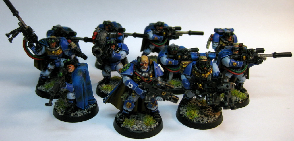
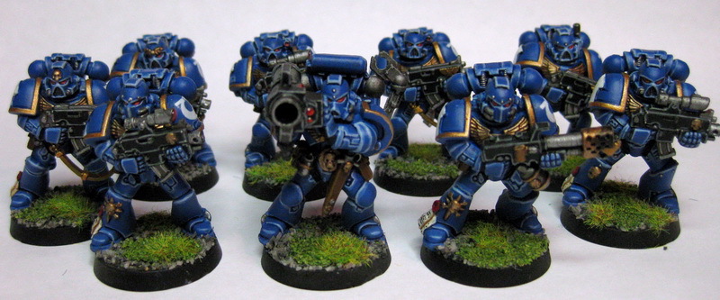
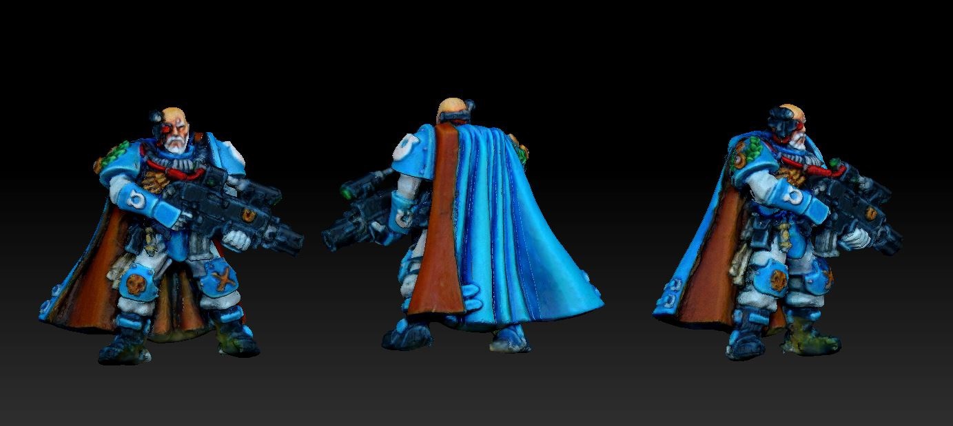
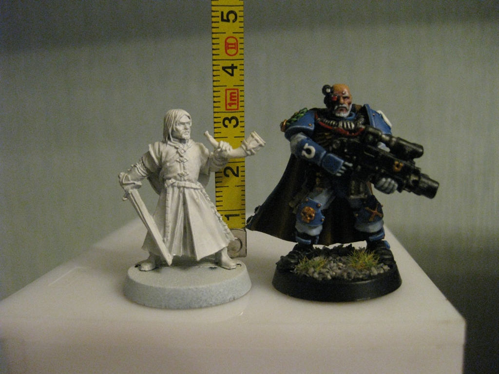
I needed accuracy, because the main thing that I wanted to scan was miniatures from the Warhammer board game (so that I could change them later, as I would like to print :)). At the height of these "soldiers" only 3 cm, but this does not prevent them from being very detailed.
')
If you do not need to remove such small objects, then you will have lower equipment requirements, and therefore it will be much easier to assemble a similar scanner for yourself.
The principle of operation of the program, and accordingly scanning, is well described in the article referenced above (I think it is not necessary to duplicate it). It is advisable to read that article first, since this will be in some way a logical continuation.
But let's start in order. What you need in order to try out a 3D scan at home:
1 - the projector.
2 - webcam.
Actually everything, the short list turned out to be surprising. Nevertheless, if you want to get very accurate and high-quality scans, you will have to modify something with pens. Of course, there is no need to do without additional costs, but in the end it will still be cheaper than buying any 3D scanner available for sale, and you can get much better quality results.
Now in order and in detail.
PROJECTOR.
I, like the author of the previous article, began my first scanning experiments with a laser pointer, but they immediately showed how inconvenient this was. There are several disadvantages here:
- the impossibility of obtaining a beam with a rather thin line. Moreover, when the pointer is rotated, the distance from the lens to the object changes, which means that the focus is lost.
- if you need to scan regularly, turning the laser pointer with sufficient accuracy and smoothness by hand is very difficult, and it is tiringly easy - hands are not that stable when it comes to a long time.
- it is necessary to scan in the dark, so that only the laser line can be seen and nothing more.
And if the second drawback can still be fought by creating a special turning mechanism (although this is not a simple task, in any case it’s not done in 5 minutes on the knee), then getting rid of the first drawback is more expensive.
When I realized all this, I decided to try scanning with the help of a projector, for which I took some simple model from a friend for a while.
There should be a slight clarification - in the last article, the author mentioned the possibility of scanning using a projector, although the proposal was, in my opinion, very strange -
A projector with a powerful lamp whose light needs to be directed through a narrow slit at the scanned object will do.
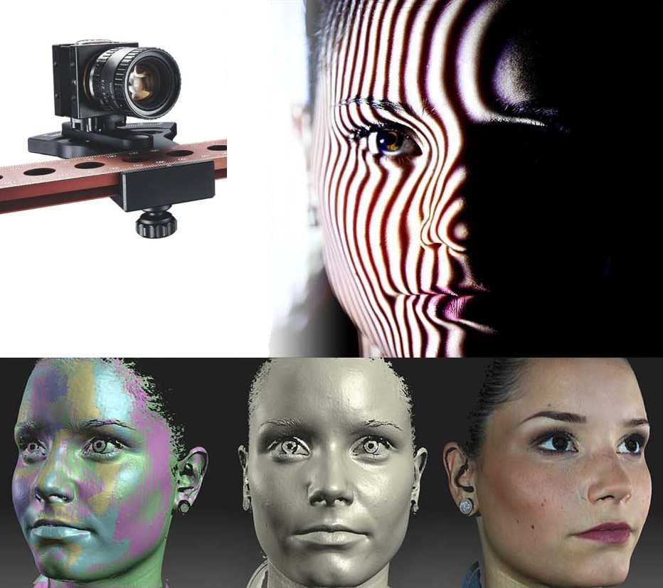
Perhaps in the earlier versions of the program it was the only option, but in version 3 with which I experimented, the projector was used much better, because there is a feature called Structured Light Scanning (SLS). Unlike laser scanning, the projector immediately projects a grid of vertical and horizontal lines of varying thickness onto the object, which reduces the scanning time by an order of magnitude and allows you to remove the colored texture of the object in an automatic mode. Well, with good focus, the line is 1 pixel wide much thinner than you can get from an inexpensive laser pointer.
Unfortunately, I didn’t take photographs from those first experiences, and there wasn’t anything special to photograph - the projector is on the table, the webcam is next to it, it all looks the same way :) However, even this simplest design showed that this option is much preferable both in scanning speed and quality. Then I decided to buy a projector for this purpose.
The criteria for choosing a projector were simple - the resolution is larger, the price and dimensions are smaller :)
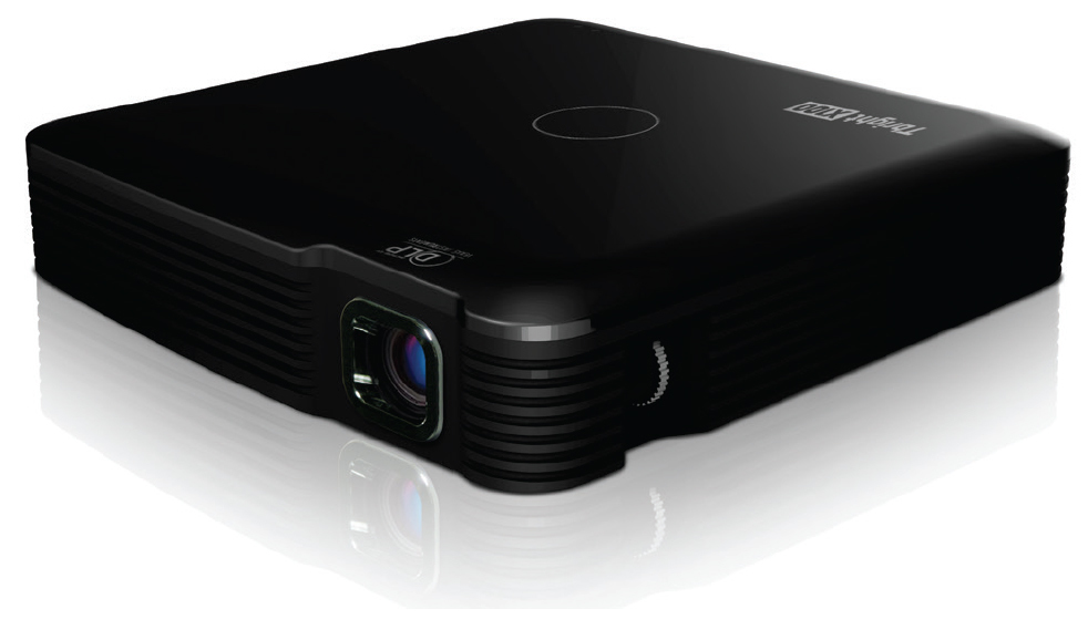
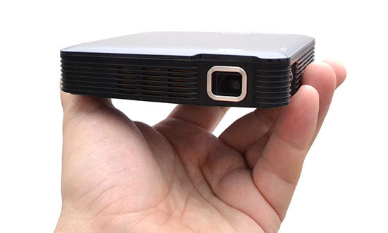
I chose the IconBit Tbright x100 - an ultra-compact DLP LED projector, 1080 resolution - at that time it seemed to me that you couldn’t think better, but as it turned out later, I was mistaken, although I got a lot of interesting experience.
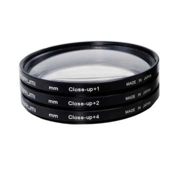
The first problem that arises when a small object is scanned with a projector is that, for best results, the size of the projected grid should roughly correspond to the size of the scanned object. This projector made it possible to get the smallest screen diagonal at the closest focus - approximately 22 cm. Agree that on such a background a miniature 3 cm high is far from the concept of “approximately equal dimensions”. The answer was found on the official forum - people in such cases install camera lenses on the projector for macro photography. Given the small size of the lens of the projector, I opted for marumi lenses with a thread diameter of 34 mm.
Using two such sets, we managed to get a projector screen with a diagonal of only about 3 cm. What was enough to make my first microscan -
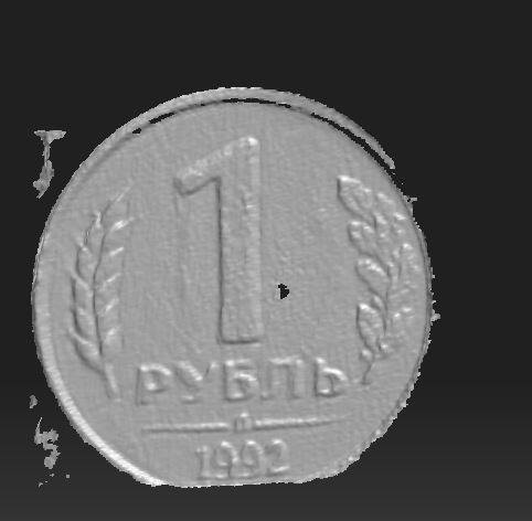
This is a single scan, so there are “holes” on the model, torn edges, etc. By turning the coin and scanning from different angles, you can get several such scans, which are subsequently combined into one object (the scanning program itself allows you to correctly combine different scans, stitch them and save them as a single object). In the process of stitching at the same time the form of the object is specified. But to save the results of such stitching is possible only after purchasing a license.
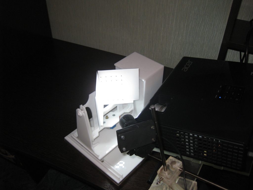
And here came the moment of the first thing, which is not necessary for scanning, but with it the process is much more convenient - it is a stand under the projector with a camera. The calibration process itself is needed not only for the program to know the parameters of the equipment - the software also has to spread the relative position of the camera and the projector. In the process of work, their change is not allowed (as well as changing the focus of the camera), which means that all this needs to be firmly fixed, because the number of scans can be large even for one object.
On the main page of David, a similar system is depicted - it is nothing complicated. And looking through the forum and seeing how different people organize it for themselves, I realized that nothing complicated is required here.
For these purposes, a stand was taken from the burned-out LCD monitor, and the plexiglas from it was cut out and glued together such a structure, as it looked in the first version
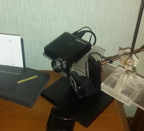
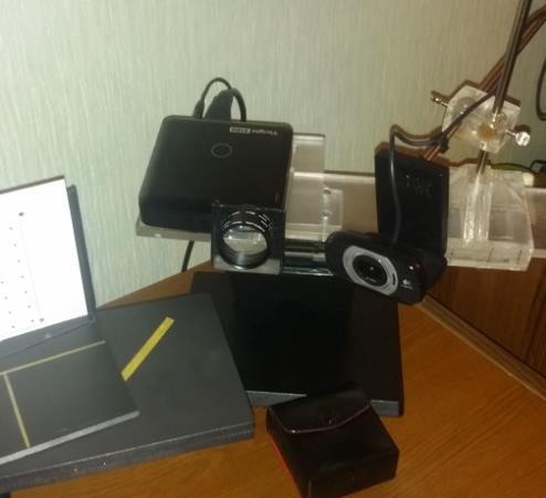
To the stand for the projector and fasteners were attached to install various lenses, allowing you to change the diagonal of the screen, and scan objects of different sizes.
It should also be mentioned that scanning with a projector does not require that the calibration panels remain in the field of view. Once calibrated, they can be removed. This allows you to calibrate the installation easy to move it, move, etc.
That is, you can use a large gauge template to calibrate the houses on the walls, and then go outside with this rack and laptop and scan your car, for example. They took a smaller template, put a pair of lenses - and you can scan jewelry.
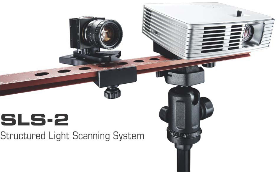
Recently, the company has released an improved set for scanning, and there the stand already looks much more serious and interesting -
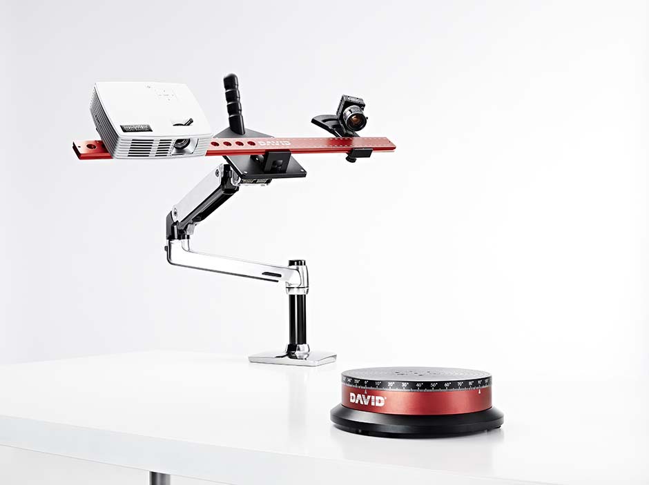
As for me, with the cost of a license for the program about $ 500 (they have recently raised the price), it’s not entirely justified to give more than 2000 euros for such a set, it is not difficult to assemble something like this and it is much cheaper.
Let's go back to the projector. As it turned out, this projector had one major drawback for use in the scanner, namely its native resolution (854 * 480). And everything would be fine if he would output the same at the output, but alas - the picture was converted to standard resolutions (such as 1024 * 768), and as a result, the line with a width of one pixel was in different parts of the screen somewhere brighter, where something dimmer, somewhere already and somewhere wider ... All this had a negative impact on the quality of scanning, to put it in the form of ripples and stripes on the resulting model.
By that time I was already thinking about buying a projector for a stereolithographic 3D printer ( http://geektimes.ru/post/245590/ ). Having considered several options, I settled on the Acer P1500, because it does not need any modifications for use in the printer (this projector without any lenses can give a focused image on the screen of about 4 * 7 cm). So, and for the scanner, it fits perfectly. At the same time, the resolution in 1920 * 1080 is real. So it turned out, I still use this projector so far and are completely satisfied with the results.
CAMERA.
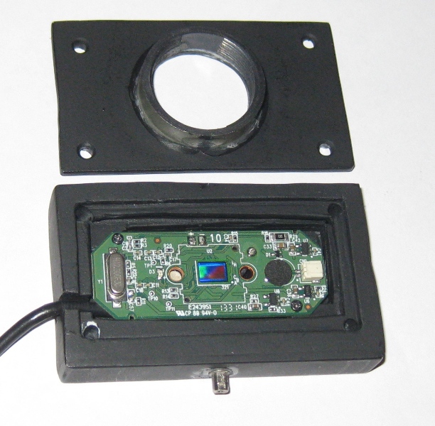
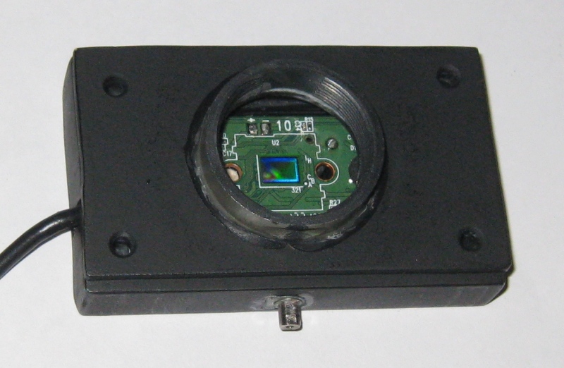
The criteria for choosing a camera were the same as when choosing a projector. Going shopping, stopped at the Logitech C615. The scan of the coin was made from it, without any modifications. But when I tried to scan the figure, I encountered a difficulty called “depth of field." When the object is so small, we actually get macro shots, and the sharpness in such shooting is achieved only in a small segment, literally just a couple of millimeters (that is why the coin scanned well - the relief fit well into the field of sharpness). It was decided to remake the camera under a different lens. On Ebay, several different lenses were ordered for testing, and a new case was cut out for the camera board. The plan was

The final result was slightly different.
The basic idea, I think, is understandable. And now on Thingiverse and on the program's forum, you can download the stl for printing cases for different types of webcams.
I had to remove the standard lens from the camera board, and as it turned out later, the IR filter was removed with it, so be careful in this matter. The filter is then useful for use with other lenses, although it is possible to purchase them separately - the price is cheap.
Thus, I have such a collection of lenses formed.
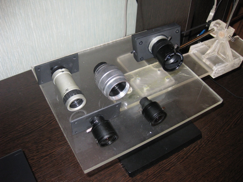
While I was expecting the delivery of lenses, various photography forums were being read. Studying the issue with depth of field, I found out that you can increase it more by closing the lens aperture. And this meant that a lens was needed in which there was an opportunity to adjust the diaphragm (alas, not everyone among those ordered had such an opportunity, but fortunately for me and a couple of them I got). In general, to improve the camera, it is desirable to have a varifocal lens with a zoom and adjustable aperture. In practice, everything turned out the way it was in theory - by closing the diaphragm, it was immediately obvious that the depth of field was increasing, which allowed scanning volume, but small objects.
The main lens that I use is in the photo above installed on the camera. The second, with adjustable aperture, is the largest in the center. I use it for very small objects. The rest without a diaphragm, so I do not use them - it turned out that these two were quite enough.
The plans now are either to find a high resolution webcam (the quality and detail of the scans directly depend on the camera resolution), or try using a digital camera with the ability to shoot video for these purposes - usually they can have a much higher resolution, and better lenses .
Actually, this could be the end - like he told about everything. I also thought that this was the end of the assembly of the scanner, but the farther into the forest ... Studying the forum of this program, I often ran into various schemes of turntables - the benefit of the software allows you to automate the scanning process. After one scan, a command is sent to the com-port, the turntable rotates, turning the object by a specified number of degrees, and gives the command to the next scan. As a result, with one click of the mouse we have circular scans of the object - it would seem, what more could we want? I tried this system with interest, but alas, I absolutely did not like this approach, and for a couple of reasons.
1 - if an object has a complex shape, then simply rotating it will not be enough - you also need to tilt it in different directions so that the camera with the projector reaches all the cavities and other hard-to-reach places.
2 - even if there are no such places, and considering all the scans that were made, there are no parts left on the object that did not get into the scan, the question remains as to the accuracy of the scan.
Suppose some part of the model on one of the scans came out perfectly. But this does not mean that on all the scans into which this part has hit, it also looks perfect, and when stitching scans from different angles, the result will be averaged, which cannot please. The program allows you to slightly edit the scans (you can cut out the unnecessary part). If we rotate the model by 20 degrees, it means that after a full turn we will have 18 scans, the part we need may well be present on half of them, therefore, in order to leave the best result, it will be necessary to remove this piece from 8 scans ... And such pieces with a complicated There can be many models, as a result, almost half of each scan will be cut off, which is very laborious and time consuming.
Instead, it is better to immediately scan adjacent areas after the first scan and check the result. As soon as some piece is ready, we proceed to scanning the next one, and so on, until the whole model is in perfect shape. This approach gives the best result in less time.
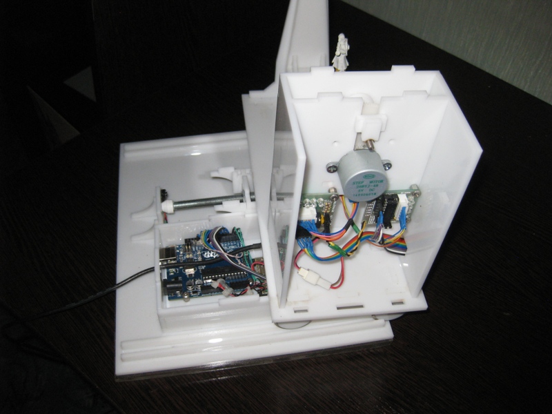
But the question of convenience arises. Agree, it is inconvenient to manually try to twist the object, not looking at it, but at the monitor - in order to control the lens, without changing the distance to the camera and the projector (so that the focus is not lost). With another similar balancing act, I accidentally touched the camera, which accordingly knocked down the entire calibration, and the whole process had to be restarted. I categorically did not like this alignment, and after some reflections I came to the plan of such a construction (which, as you understand, later I put together).
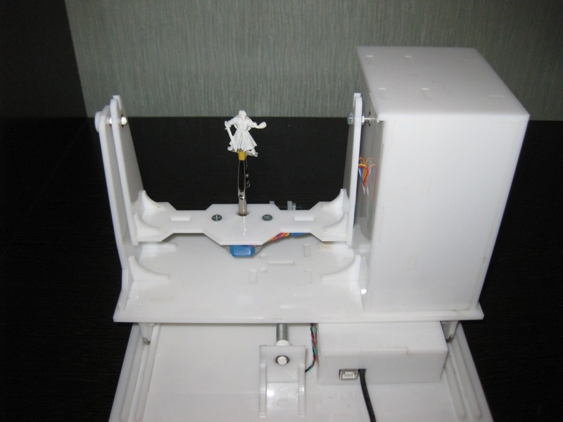
This is not a turntable in the usual sense of the term. Thanks to this design, I can not only rotate the model, but also tilt it as I need it. At the same time, the center of the model remains in the plane of focus, but even if it does not exist, you can move the mount with the model back and forth.
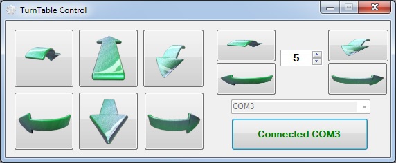
All this gathered on Arduino, a small program for management was written, and as a result, I now do not have to get up from the computer when scanning - using the program, I change the position of the scanned object, and at the same time, in the camera window, I choose the optimal one for scanning angle
Insides
In the program, I laid the possibility of automatic scanning, as well as scanning is not easy in a circle, and with inclinations of 45 degrees in one and the other direction, which gives three times more scans. However, in the end, I never use this opportunity anyway - it is too inconvenient then to understand the received heap of scans and clean them from unsuccessful pieces.
It should also mention some of the nuances of scanning.
1 - it is impossible to scan shiny and mirror surfaces. Light from them is reflected, or gives such a flare that the program can not correctly recognize the line. If there is a need to scan such an object, then such parts will have to be disguised with something (washable paint, paper tape, etc.).
2 - it is more convenient to scan monotonous objects, since when adjusting the camera to a light color, the projection brightness is not as high, the exposure is low, etc. And for an object of dark color, greater brightness is required, so if you have a multi-colored object, then for its different parts different settings are required to obtain the best result. Here, too, it is more convenient to use object scanning in parts.
3 - if you want to immediately get a color texture, then note that the settings of the camera and the projector for the scan do not affect the settings for removing the texture (the scan is generally done in black and white), so play around with the settings in the texture mode as you will do in scan mode.
The scanning process for me now looks like this:
- Focusing the projector and camera
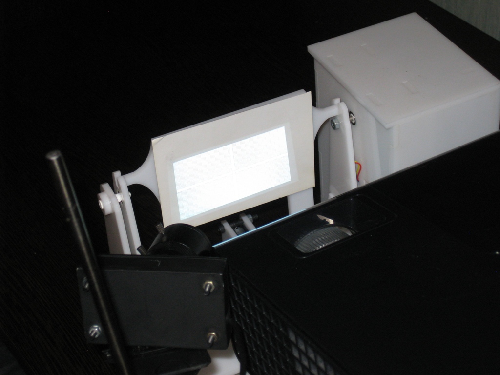
The light of the projector is too bright and the projected grid is not visible in the photo, but here is a view from the camera in the program
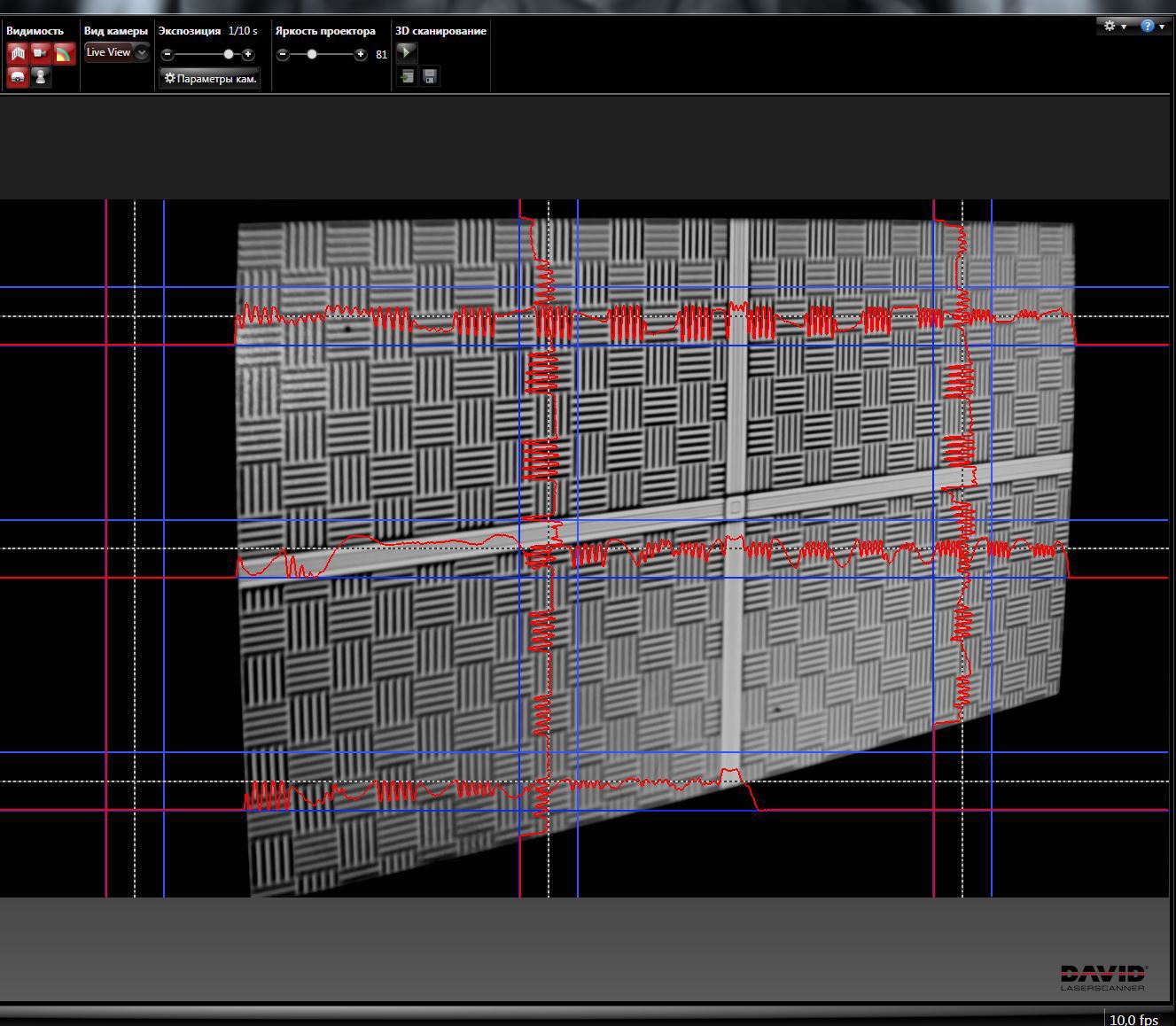
- scanner calibration
The gauge corner was made of metal plates, and gauge patterns of different sizes were printed on magnetic paper - so you can very quickly adjust to different sizes of scanned objects.
View in the program
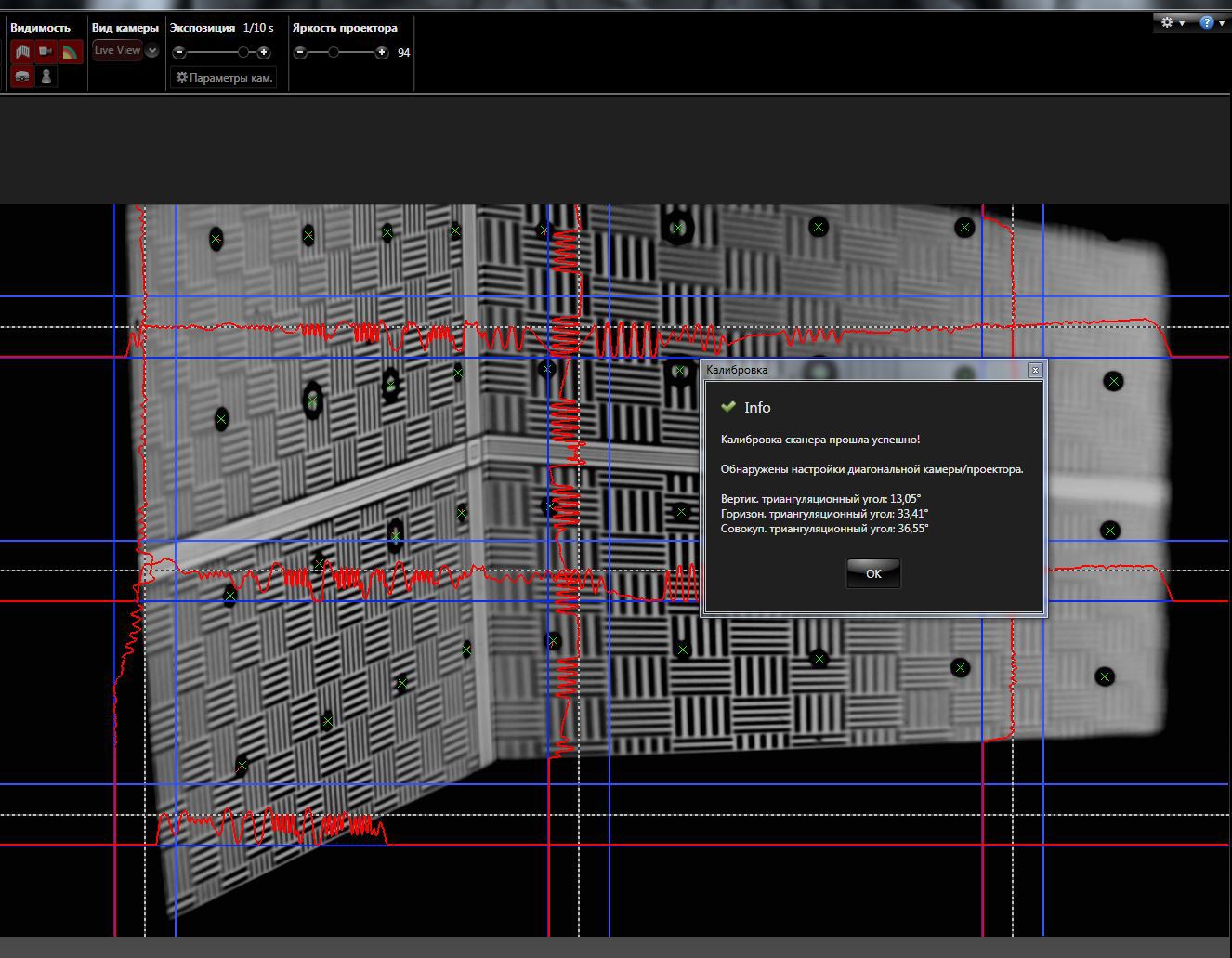
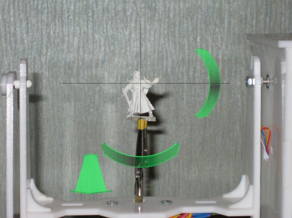
It is recommended that the cumulative angle between the beam of the projector and the camera is about 20 degrees. Therefore, such a rack is used - when scanning large objects (for example, a person), the camera should be set aside much further from the projector, but here they stand close to me. The location of the camera relative to the projector can only be vertical, or only horizontal - depending on the geometry of the object. In this case, the location is diagonal (13 degrees vertically and 36 horizontally).
Scan results from different angles. These are already cleaned up scans, i.e. removed all unsuccessful and unnecessary parts (frame stand, frame fitting).

Combining scans for later merging into one object
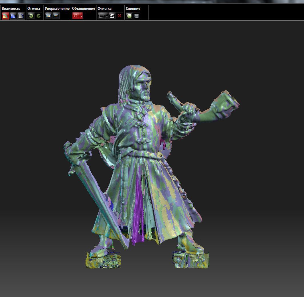
Due to the fact that each scan has its own color, it is convenient to control the correctness of the combination.
Well, after combining scans from different angles, we get these models
Miniature of Boromir from the Lord of the Rings.
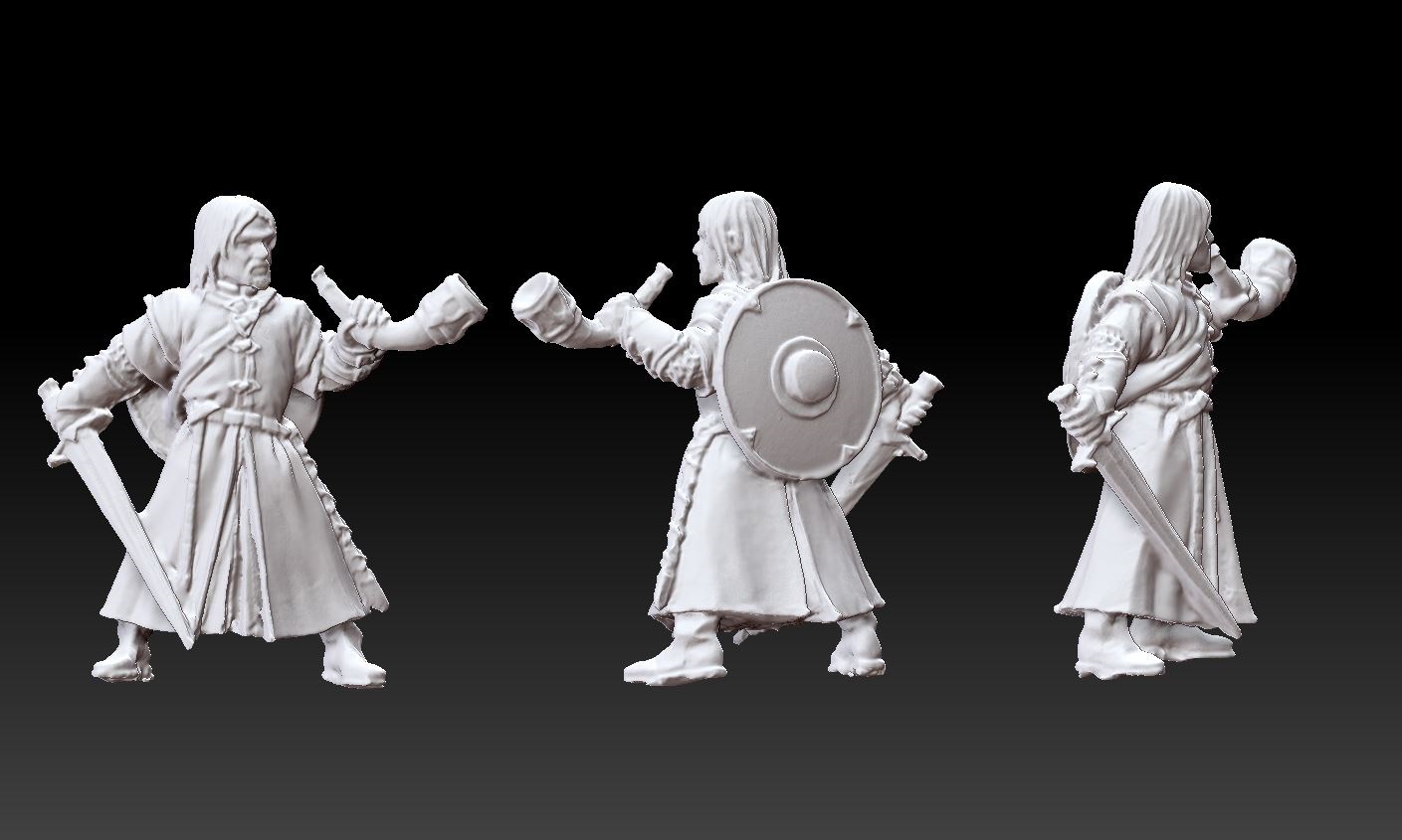
When scanning a multi-colored object, the result is slightly worse if you don’t bother much. But you can get the object immediately with the texture :)
Original models
In the user work gallery on the developer’s website ( http://www.david-3d.com/en/news&community/usergallery ) you can find many more interesting scans, even people scan fingerprints. And there are even scans of the same thumbnails from Warhammer
In conclusion, I would like to say that no matter what hardware you use, whatever expensive 3D scanner you buy, but this is not a panacea for printing anything. Theoretically, of course, you can send the resulting object to the slicer and print, but there are several reasons why you shouldn’t do that, but you should in any case study 3D graphics packages.
1 - The resulting scans, with good scan quality (and we want to get the best quality) have a lot of polygons. No, even VERY MUCH . After the merger, the Boromir scan contained more than 8 million polygons - not every slicer can work with such an object.
2 - Any objects carry traces of assembly and manufacturing. And if in reality files and sandpaper are used to fix this (and sometimes there are still inaccessible places where tools cannot be used), then working with a digital copy of an object, we can change it as you please — remove defects, improve detailing, etc. .
3 - As I said at the beginning of the article, when I thought about the scanner, I didn’t want to print copies of objects, but to change them as I liked. I am not a sculptor, I do not have the tools, materials and skills to fashion such a small model. But being able to work in 3D, it is much easier for me, having scanned a similar Boromir, to make him a prince of Danish.
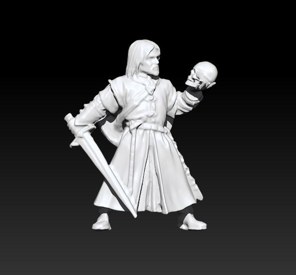
By the way, this model already contains almost 100 times less polygons than the scan result.
Source: https://habr.com/ru/post/367719/
All Articles