Vector control of the electric motor "on the fingers"
- What is vector control?
- Keep current at 90 degrees.
 The term "vector control" of electric motors is familiar to anyone who is at least somehow interested in the question of how to control an AC motor using a microcontroller. However, usually in any book on the electric drive, the chapter on vector control is located somewhere near the end; it consists of a pile of hairy formulas with references to all other chapters of the book. Why do not want to understand this issue. And even the simplest explanations still keep their way through differential equilibrium equations, vector diagrams, and a bunch of other mathematics. Because of what there are about here, such attempts to somehow spin the engine without using mat. Parts. But in fact, vector control is very simple, if you understand the principle of its work "on the fingers." And there it will be more fun to deal with formulas if necessary.
Consider the principle of operation of the simplest AC motor - a synchronous machine with permanent magnets. A convenient example is the compass: its magnetic needle is the rotor of a synchronous machine, and the magnetic field of the Earth is the magnetic field of the stator. Without an external load (and it is not in the compass, except for friction and fluid damping the oscillations of the arrow), the rotor is always oriented along the stator field. If we hold the compass and rotate the Earth beneath it, then the arrow will spin after doing the work of mixing the fluid inside the compass. But there is a slightly simpler way - you can take an external magnet, for example, in the form of a rod with poles at the ends, the field of which is much stronger than the magnetic field of the Earth, bring it to the compass from above and rotate the magnet. The arrow will move after the rotating magnetic field. In a real synchronous motor, the stator field is created by electromagnets - coils with current. The windings are complex, but the principle is the same - they create a magnetic field with the stator, which is directed in the right direction and has the required amplitude. Let's look at the following figure (Figure 1). In the center there is a magnet - a rotor of a synchronous motor (“arrow” of a compass), and on the sides there are two electromagnets - coils, each creating its own magnetic field, one in the vertical axis and the other in the horizontal.
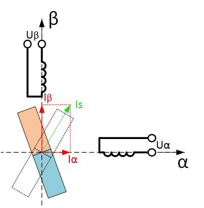
Figure 1. The principle of operation of a synchronous electric machine
')
The magnetic flux of the coil is proportional to the current in it (as a first approximation). We will be interested in the magnetic flux from the stator in the place where the rotor is located, i.e. in the center of the picture (edge effects, scattering and everything else is neglected). The magnetic fluxes of two perpendicularly arranged coils are vector-fold, forming one common flow for interaction with the rotor. But since the flow is proportional to the current in the coil, it is convenient to draw directly the vector of currents, aligning them with the flow. The figure shows some currents I α and I β , creating magnetic fluxes along the axes α and β, respectively. The total vector of the stator current I s creates a stator magnetic flux directed to it. Those. in fact, I s symbolizes the external magnet, which we brought to the compass, but created by electromagnets - coils with current.
In the figure, the rotor is located in an arbitrary position, but from this position the rotor will tend to rotate according to the magnetic flux of the stator, i.e. on the vector I s (the position of the rotor in this case is shown by a dotted line). Accordingly, if only current is supplied to the α phase, say, I α = 1, the rotor will rise horizontally, and if in β, vertically, and if I attach β = -1, it will turn 180 degrees. If the current I α is powered by the sine law, and I β by the cosine law of time, a rotating magnetic field will be created. The rotor will follow it and spin (like a compass needle follows the rotation of the magnet with your hands). This is the basic principle of operation of a synchronous machine, in this case two-phase with one pair of pluses.
Let's draw a graph of the motor torque depending on the angular position of the rotor shaft and the stator current vector I s - the angular characteristic of a synchronous motor. This dependence is sinusoidal (Figure 2).

Figure 2. The angular characteristic of a synchronous machine (there is some historical confusion with the signs of the moment and angle, which is why they often draw the characteristic inverted relative to the horizontal axis).
To get this graph in practice, you can put a torque sensor on the rotor shaft, then turn on any current vector, for example, simply feed current into the α phase. The rotor will turn to the appropriate position, which must be taken as zero. Then, through the moment sensor, “rotate” it is necessary to turn the rotor, fixing the angle θ , which was turned, on the graph at each point, and the moment that the sensor showed. Those. you need to stretch the "magnetic spring" of the engine through the torque sensor. The biggest moment will be at an angle of 90 degrees from the current vector (from the beginning). The amplitude of the resulting maximum moment M max is proportional to the amplitude of the applied current vector. 1A will be applied, we get, say, M max = 1 N m (newton * meter, unit of torque), if we give 2A, we get M max = 2 N m.
From this characteristic it follows that the motor develops the greatest moment when the rotor is under 90 ° to the current vector. Since when we want to create a control system on a microcontroller, we want to get the greatest moment from the motor with minimum losses, and the loss, first of all, is the current in the windings, it is more rational to put the current vector always at 90 ° to the rotor magnetic field, i.e. perpendicular to the magnet in Figure 1. It is necessary to change the opposite: the rotor does not go to the current vector we specify, and we always set the current vector 90 ° to the rotor, no matter how it rotates, i.e. “Nail” the current vector to the rotor. To regulate the moment of the motor will be the current amplitude. The greater the amplitude, the higher the moment. And the rotational frequency, current frequency in the windings is already “not our” business - what happens, the rotor will rotate, so will it be - we control the torque on the shaft. Oddly enough, this is what is called vector control - when we control the stator current vector so that it is under 90 ° to the rotor magnetic field. Although some textbooks give broader definitions, to the extent that vector management generally refers to any control laws where “vectors” are involved, but usually, vector control is understood to mean exactly the above control method.
But how is vector control achieved in practice? Obviously, you first need to know the position of the rotor, so that it is relative to what to measure 90 °. It is easiest to do this by installing, in fact, the position sensor on the rotor shaft. Then you need to figure out how to create a current vector, maintaining the desired currents in the α and β phases. We apply voltage to the motor, not current ... But since we want to support something, we need to measure it. Therefore, for vector control, we need phase current sensors. Next you need to collect the structure of the vector control in the form of a program on the microcontroller, which will do the rest. So that such an explanation does not look like a “how to draw an owl” instruction, let's continue the dive.
You can maintain the current by the microcontroller using a software PI (proportional-integral) current controller and PWM. For example, a structure with a current regulator for a single phase α is shown below (Figure 3).
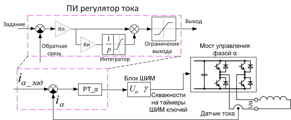
Figure 3. Current-closed control structure for a single phase
Here, setting the current i α_ass is a certain constant, the current that we want to support for this phase, for example, 1A. The task arrives at the current controller adder, the disclosed structure of which is shown above. If the reader does not know how the PI controller works, then alas. I can only advise some of this . The output current controller sets the phase voltage U α . The voltage goes to the PWM block, which calculates the duty ratio (setpoint comparison) for the PWM timers of the microcontroller that form the PWM on the bridge inverter of four keys to form this U α . The algorithm can be different, for example, for a positive voltage, the PWMM of the right stance is proportional to the voltage setting, the lower key is closed on the left, the left key is for negative PWM, the lower key is closed on the right. Do not forget to add dead time! As a result, such a structure makes a software “current source” at the expense of a voltage source: we set the desired value i α_ass , and this structure with a certain speed implements it.
Further, perhaps, some readers already thought that the small vector structure remained to be managed - you need to put two current regulators, for each phase of the regulator, and to form them a task depending on the angle from the rotor position sensor (DPR), t. e. make something like this structure (Figure 4):

Figure 4. Wrong (naive) vector control structure
So you can not do. When the rotor rotates, the variables i α_ass and i β_ass will be sinusoidal, i.e. the task for current regulators will change all the time. The speed of the regulator is not infinite, so when you change the job, it does not instantly work it out. If the task is constantly changed, the regulator will always catch up with it, never reaching it. And with the growth of the motor rotation speed, the lag of the real current from the set point will be more and more, until the desired angle of 90 ° between the current and the rotor magnet does not cease to look like it at all, and the vector control does not cease to be so. Therefore, they do it differently. The correct structure is as follows (Figure 5):

Figure 5. The structure of the vector sensor control for a two-phase synchronous machine
Two blocks were added here - BKP_1 and BKP_2: blocks of coordinate transformations. They do a very simple thing: turn the vector at the entrance at a given angle. Moreover, BOD_1 turns on + ϴ , and BKP_2 on - . This is all the difference between them. In foreign literature, they are called Park transformations. BKP_2 makes the transformation of coordinates for currents: from fixed axes α and β , attached to the stator of the engine, to rotating axes d and q , attached to the rotor of the engine (using the rotor angle for this). And BKP_1 does the inverse transformation, from the setting of the voltage along the axes d and q makes the transition to the axes α and β . I don’t give formulas for coordinate transformation, but they are simple and very easy to find. Actually, there is nothing more complicated in them than school geometry (Figure 6):

Figure 6. Coordinate transformations of the fixed axes α and β, attached to the stator of the engine, to the rotating axes of the axes d and q , attached to the rotor
That is, instead of “rotating” the tasks of the regulators (as was the case in the previous structure), their inputs and outputs rotate, and the regulators themselves operate in a static mode: the currents d , q and the outputs of the regulators in the steady state are constant. The d and q axes rotate with the rotor (this is how the signal from the rotor position sensor rotates them), while the q axis regulator controls exactly the current that I called “perpendicular to the rotor field” at the beginning of the article, that is, the current-forming current, and the current d is co-directed with the “rotor magnet”, so we do not need it and we set it equal to zero. This structure is free from the lack of the first structure - the current regulators do not even know that something is spinning somewhere. They work in a static mode: they have adjusted each of their currents, reached a predetermined voltage - and everything, like the rotor, do not run away from them, they don’t even know about it: all the work on turning is done by blocks of coordinate transformations.
The above structure really works and is used in modern electric drives. Only it lacks a whole heap of small “improvements”, without which it is no longer customary to do it, such as compensating for cross-links, various restrictions, weakening the field, etc. But the basic principle is this.
And if you need to adjust not the drive torque, but still the speed (at the correct angular speed, rotational speed)? Well, then put another PI controller - speed controller (PC). At the input we give the speed reference, and at the output we have the torque reference. Since the current q axis is proportional to the moment, it is possible to simplify the output of the speed controller to be fed directly to the input of the current controller of the q axis, like this (Figure 7):

Figure 7. Speed control for vector control
Here ZI is the master of intensity, smoothly changing its output so that the engine accelerates at the right pace, and does not drive at full current to set the speed. The current rotational speed ω is taken from the rotor position sensor handler, since ω is the derivative of the angular position. Well, or you can just mark the time between sensor pulses ...
How to do the same for a three-phase motor? Well, actually, nothing special, add another block and change the PWM module (Figure 8).

Figure 8. The structure of the vector sensor control for a three-phase synchronous machine
The three-phase currents, just like the two-phase currents, serve the same purpose — to create a stator current vector I s directed in the right direction and having the required amplitude. Therefore, three-phase currents can be simply converted into two-phase, and then leave the same control system that has already been collected for a two-phase machine. In the English-language literature, such a “recalculation” is called Clark transformations - the Clarke transformation (Edith Clark is her), in our country - phase transformations. In the structure in Figure 8, respectively, this operation is performed by a block of phase transformations. They are done again with the help of the school geometry course (Figure 9):

Figure 9. Phase transformations - from three phases to two. For convenience, we assume that the amplitude of the vector I s is equal to the amplitude of the current in the phase
I think comments are not needed. A few words about the current of phase C. There can be no current sensor, as the three phases of the motor are connected to a star, and according to Kirchhoff's law, everything that flowed through two phases must flow out of the third (unless, of course, you have broken through the motor insulation, and half did not flow away somewhere on the case), therefore, the current of phase C is calculated as the scalar sum of the currents of phases A and B with a minus sign. Although the third sensor is sometimes set to reduce the measurement error.
Also need a complete rework of the PWM module. Typically, three-phase motors use a three-phase six-key inverter. In the figure, the voltage reference still arrives in two-phase axes. Inside the PWM module, using reverse phase transformations, it is possible to recalculate this into voltages of phases A, B, C, which must be applied at this moment to the motor. But what to do next ... There are options. The naive method is to set a porosity for each rack of the inverter proportional to the desired voltage plus 0.5. This is called sinusoidal PWM. This is the method used by the author in habrahabr.ru/post/128407 . In this method, everything is fine, except that the inverter is underused by this method - i.e. The maximum voltage that will be received will be less than what you could have received if you used a more advanced PWM method.
Count. Suppose you have a classic frequency converter powered by an industrial 380V 50Hz network. Here, 380V is the linear (between phases) effective voltage. Since there is a rectifier in the converter, it will rectify this voltage and on the DC bus there will be a voltage equal to the amplitude linear voltage, i.e. 380 √2 = 540V DC (at least without load). If we apply a sinusoidal calculation algorithm in the PWM module, then the amplitude of the maximum phase voltage that we can do will be equal to half the voltage on the DC bus, i.e. 540/2 = 270V. Recalculate in the current phase: 270 / √2 = 191V. And now in the current linear: 191 ∙ √3 = 330V. Now we can compare: the 380V came in, but the 330V came out ... And it’s impossible with this type of PWM anymore. To correct this problem, the so-called vector PWM type is used. In it, the output will again be 380V (ideally without taking into account all voltage drops). The vector PWM method has no relation to the vector control of the electric motor. It's just that a little bit of school geometry is used again in its justification, which is why it is called vector geometry. However, his work on the fingers cannot be explained, so I will send the reader to the books (at the end of the article) or to Wikipedia . I can also give a picture that hints a little at the difference in the work of sinusoidal and vector PWM (Figure 10):
Figure 10. Phase potential variation for scalar and vector PWM
By the way, what position sensors are used for vector control? Four types of sensors are most commonly used. This is a quadrature incremental encoder, a sensor based on Hall elements, an absolute position sensor and a selsyn sensor.
The quadrature encoder does not give out the absolute position of the rotor - it only allows you to determine how far you have passed, but not where and from where (as the beginning and the end are related to the location of the rotor magnet). Therefore, it is not suitable for vector control of a synchronous machine. His reference mark (index) saves the situation a little - it is one for a mechanical turn, if you reach it, then the absolute position becomes known, and you can already count from it how many have passed by a quadrature signal. But how to get to this tag at the beginning of work? In general, it is not always convenient.
A sensor based on Hall elements is a coarse sensor. It gives out only a few impulses per revolution (depending on the number of Hall elements, for three-phase motors there are usually three, that is, six impulses), allowing one to know the position in absolute value, but with low accuracy. Accuracy is usually enough to keep the angle of the current vector so that the motor will at least drive forward and not backward, but the moment and the currents will pulsate. If the engine is overclocked, then you can begin to extrapolate the signal from the sensor over time, ie build a linearly varying angle from a coarse discrete angle. This is done on the basis of the assumption that the engine rotates at approximately constant speed, something like this (Figure 11):

Figure 11. Position sensor operation on Hall elements for a three-phase machine and extrapolation of its signal
Often for servomotors, a combination of an encoder and a Hall sensor is used. In this case, you can make a single software module for processing them, removing the flaws of both: do extrapolation of the angle given above, but not by time, but by tags from the encoder. Those. inside from the front to the front of the Hall sensor, the encoder works, and each Hall front clearly initializes the current absolute angular position. In this case, only the first movement of the actuator will be suboptimal (not under 90 °), until it reaches some front of the Hall sensor. A separate problem in this case is the processing of non-ideality of both sensors - symmetrically and evenly, Hall elements are rarely available to ...
In even more expensive applications, an absolute position sensor with a digital interface (absolute encoder) is used, which immediately gives an absolute position and allows you not to experience the problems described above.
If the motor is very hot, and also when increased accuracy of angle measurement is required, use an “analog” selsyn sensor (resolver, rotary transformer). This is a small electric machine used as a sensor. Imagine that in the synchronous machine we considered in Figure 1, instead of magnets there is another coil to which we give a high-frequency signal. If the rotor is horizontal, the signal will only hover over the stator coil of the phase α , if it is vertical - only at β , if you turn it up 180 - the signal phase changes, and in intermediate positions it is induced both to and fro according to the sine / cosine law. Accordingly, by measuring the amplitude of the signal in the two coils, the position can also be determined from the ratio of this amplitude and phase shift. By installing such a machine as a sensor to the main one, you can recognize the position of the rotor.
There are still many exotic position sensors, especially for ultra high precision applications, for example, for the manufacture of electronic chips. There, any physical phenomena are already being used, in order to only know the position most accurately. We will not consider them.
As you understand, the vector control is quite demanding - both the position sensors and the current sensors, and the PWM vector control, and the microcontroller aren't anyhow, so as to cheat all this math. Therefore, for simple applications it is simplified. For starters, you can eliminate the position sensor by making sensorless vector control. To do this, use a little more mathematical magic, located in the yellow rectangle (Figure 12):

Figure 12. The structure of the sensorless vector control
An observer is such a unit to which information is supplied on the voltage applied to the motor (for example, from a task to the PWM module) and on currents in the engine from sensors. Inside the observer, a model of an electric motor is working, which, roughly speaking, is trying to adjust its currents in the stator to those measured from a real engine. If she succeeds in this, then we can assume that the position of the rotor simulated inside the shaft also coincides with the real one and can be used for the needs of vector control. Well, this, of course, is very simplistic. Types of observers such - do not count. Each graduate student in the specialty "electric drive" is trying to invent his own, which is something better than others. The basic principle is tracking the EMF of an electric motor. Therefore, most often the sensorless control system is operable only at a relatively high rotational speed, where the EMF is large. It also has a number of drawbacks compared with the presence of a sensor: you need to know the parameters of the engine, the drive speed is limited (if the rotational speed changes dramatically, the observer may not be able to track it and for some time “lie” or even “fall apart”) , setting up an observer is a whole procedure; for its high-quality work, it is necessary to know precisely the voltage on the motor, to accurately measure its currents, etc.
There is another simplification option. For example, you can do the so-called "auto switching". In this case, for a three-phase motor, the complex PWM method is abandoned, the complex vector structure is abandoned, and they simply start to turn on the motor phases using the position sensor on the Hall elements, sometimes even without any limiting. The current in the phases is not sinusoidal, but trapezoidal, rectangular, or even more distorted. But they try to make sure that the average current vector is still at 90 degrees to the “rotor magnet” by choosing the moment of switching on the phases. In this case, including the phase under voltage, it is not known when the current in the motor phase will increase. At low speeds, it does it faster, at high where the EMF of the machine interferes, more slowly, even the current rise rate depends on the motor inductance, etc. Therefore, even including the phases at exactly the right time, it’s not at all the fact that the average current vector will be in the right place and with the right phase - it can both lead and lag behind the optimal 90 degrees. Therefore, in such systems, a setting of “switching timing” is introduced - in fact, just time, as far as it is necessary to supply voltage to the motor phase so that the current vector phase is closer to 90 degrees. In simple terms, this is called "setting timings." Since the auto-switching current in the electric motor is not sinusoidal, then, if we take the above-described sinusoidal machine and control it in such a way, the torque on the shaft will pulsate. Therefore, in motors intended for auto switching, they often change the magnetic geometry of the rotor and stator in a special way so that they become more suitable for this type of control: EMF of such machines is made trapezoidal, due to which they work better in the auto switching mode. Synchronous machines, optimized for auto switching, are called brushless DC motors (BDPT) or in English BLDC (Brushless Direct Current Motor). The auto switching mode is also often referred to as the valve mode, and the engines operating with it are valve mode. But these are all just different names that have no effect on the essence (but experienced electric drivers often suffer SPPS in matters related to these names). There is a good video illustrating the principle of operation of such machines. It shows the engine facing, where the rotor is outside and the stator is inside:
And here there is a course of articles on such engines and control system hardware.
You can go even further simplification. Commute the windings so that one phase is all the time “free” and no PWM is applied to it. Then it can measure the EMF (induced voltage in the phase coil), and when this voltage passes through zero, use it as a signal of the rotor position sensor, because the phase of this induced voltage depends on the position of the rotor. It turns out to be sensorless auto switching, which is widely used in various simple drives, for example, in “regulators” for propellers of model aircraft. It should be remembered that the EMF of the machine appears only at a relatively high rotational speed, so for starting such control systems simply slowly sort out the phases, hoping that the rotor of the engine will follow the supplied current. As soon as the EMF appears, the auto-switching mode is activated. Therefore, a sensorless system (so simple, and often the most complex too) is not suitable for tasks where the engine should be able to develop a torque at near-zero speeds, for example, for a traction drive of a car (or its model), a servo drive of some mechanism, etc. P. But the sensorless system is successfully suited for pumps and fans, where it is used.
But sometimes they make an even greater simplification. You can completely abandon the microcontroller, keys, position sensors and other things by performing phase switching using a special mechanical switch (Figure 13):

Figure 13. Mechanical switch for switching windings
During rotation, the rotor itself switches its parts of the windings, changing the voltage applied to them, while the current in the rotor flows alternating. The switch is positioned so that the magnetic flux of the rotor and the stator is again close to 90 degrees in order to reach the maximum moment. Such enginesare naively called DC motors, but completely undeserved: inside, after the collector, the current is still alternating!
All electric cars work in a similar way. In electric drive theory, there is even the concept of “generalized electric machine”, to which the work of others is reduced.The explanations “on fingers” shown in the article in no way can serve as a practical guide to the writing of microcontroller code. The article is considered well if one percent of the information that is required to implement this vector control. To do something in practice, you first need to know TAU , at least at the level of understanding how the PI controller works. Then you still need to study the mathematical description of both the synchronous machine and the synthesis of vector control. Also study vector PWM, find out what pairs of poles are, get acquainted with the types of machine windings and so on. This can be done in a fresh book, “ Anuchin A. S. Control systems of electric drives. MEI, 2015 ”, and also in“ Yu. N. Kalachev. Vector regulation (practice notes)". The reader should be warned against immersion in the formulas of the “old” drive textbooks, where the main emphasis is placed on considering the characteristics of electric motors when powered directly from a three-phase industrial network, without any microcontrollers and position sensors. The behavior of the engines in this case is described by complex formulas and dependencies, but for the vector control problem they carry almost no benefit (if only studied for self-development). Especially should be wary of the recommendations of the old textbooks, where, for example, it is said that the synchronous machine should not work at the maximum of its moment, since there the work is unstable and threatens to overturn - all this “bad advice” for vector control.
Which microcontroller can be used for full vector control, read, for example, in our article New domestic motor-control microcontroller K1921VK01T of NIIET , and how to debug it in the article Methods of debugging software for microcontrollers in an electric drive . Also visit our website: there, in particular, twoboring videos are posted , where it is shown in practice how to set up a PI current controller, as well as how a closed current and vector sensorless control structure works. In addition, you can purchase a debug kit with a ready-made sensor vector control structure on a domestic microcontroller.
Continuation of the article, where it is told about asynchronous motorshere .
PS
I apologize to the experts for not quite correct handling of certain terms, in particular, the terms “flow”, “flow coupling”, “magnetic field” and others - simplicity requires sacrifices ...
- Keep current at 90 degrees.
The term "vector control" of electric motors is familiar to anyone who is at least somehow interested in the question of how to control an AC motor using a microcontroller. However, usually in any book on the electric drive, the chapter on vector control is located somewhere near the end; it consists of a pile of hairy formulas with references to all other chapters of the book. Why do not want to understand this issue. And even the simplest explanations still keep their way through differential equilibrium equations, vector diagrams, and a bunch of other mathematics. Because of what there are about here, such attempts to somehow spin the engine without using mat. Parts. But in fact, vector control is very simple, if you understand the principle of its work "on the fingers." And there it will be more fun to deal with formulas if necessary.The principle of operation of the synchronous machine
Consider the principle of operation of the simplest AC motor - a synchronous machine with permanent magnets. A convenient example is the compass: its magnetic needle is the rotor of a synchronous machine, and the magnetic field of the Earth is the magnetic field of the stator. Without an external load (and it is not in the compass, except for friction and fluid damping the oscillations of the arrow), the rotor is always oriented along the stator field. If we hold the compass and rotate the Earth beneath it, then the arrow will spin after doing the work of mixing the fluid inside the compass. But there is a slightly simpler way - you can take an external magnet, for example, in the form of a rod with poles at the ends, the field of which is much stronger than the magnetic field of the Earth, bring it to the compass from above and rotate the magnet. The arrow will move after the rotating magnetic field. In a real synchronous motor, the stator field is created by electromagnets - coils with current. The windings are complex, but the principle is the same - they create a magnetic field with the stator, which is directed in the right direction and has the required amplitude. Let's look at the following figure (Figure 1). In the center there is a magnet - a rotor of a synchronous motor (“arrow” of a compass), and on the sides there are two electromagnets - coils, each creating its own magnetic field, one in the vertical axis and the other in the horizontal.
Figure 1. The principle of operation of a synchronous electric machine
')
The magnetic flux of the coil is proportional to the current in it (as a first approximation). We will be interested in the magnetic flux from the stator in the place where the rotor is located, i.e. in the center of the picture (edge effects, scattering and everything else is neglected). The magnetic fluxes of two perpendicularly arranged coils are vector-fold, forming one common flow for interaction with the rotor. But since the flow is proportional to the current in the coil, it is convenient to draw directly the vector of currents, aligning them with the flow. The figure shows some currents I α and I β , creating magnetic fluxes along the axes α and β, respectively. The total vector of the stator current I s creates a stator magnetic flux directed to it. Those. in fact, I s symbolizes the external magnet, which we brought to the compass, but created by electromagnets - coils with current.
In the figure, the rotor is located in an arbitrary position, but from this position the rotor will tend to rotate according to the magnetic flux of the stator, i.e. on the vector I s (the position of the rotor in this case is shown by a dotted line). Accordingly, if only current is supplied to the α phase, say, I α = 1, the rotor will rise horizontally, and if in β, vertically, and if I attach β = -1, it will turn 180 degrees. If the current I α is powered by the sine law, and I β by the cosine law of time, a rotating magnetic field will be created. The rotor will follow it and spin (like a compass needle follows the rotation of the magnet with your hands). This is the basic principle of operation of a synchronous machine, in this case two-phase with one pair of pluses.
Let's draw a graph of the motor torque depending on the angular position of the rotor shaft and the stator current vector I s - the angular characteristic of a synchronous motor. This dependence is sinusoidal (Figure 2).
Figure 2. The angular characteristic of a synchronous machine (there is some historical confusion with the signs of the moment and angle, which is why they often draw the characteristic inverted relative to the horizontal axis).
To get this graph in practice, you can put a torque sensor on the rotor shaft, then turn on any current vector, for example, simply feed current into the α phase. The rotor will turn to the appropriate position, which must be taken as zero. Then, through the moment sensor, “rotate” it is necessary to turn the rotor, fixing the angle θ , which was turned, on the graph at each point, and the moment that the sensor showed. Those. you need to stretch the "magnetic spring" of the engine through the torque sensor. The biggest moment will be at an angle of 90 degrees from the current vector (from the beginning). The amplitude of the resulting maximum moment M max is proportional to the amplitude of the applied current vector. 1A will be applied, we get, say, M max = 1 N m (newton * meter, unit of torque), if we give 2A, we get M max = 2 N m.
From this characteristic it follows that the motor develops the greatest moment when the rotor is under 90 ° to the current vector. Since when we want to create a control system on a microcontroller, we want to get the greatest moment from the motor with minimum losses, and the loss, first of all, is the current in the windings, it is more rational to put the current vector always at 90 ° to the rotor magnetic field, i.e. perpendicular to the magnet in Figure 1. It is necessary to change the opposite: the rotor does not go to the current vector we specify, and we always set the current vector 90 ° to the rotor, no matter how it rotates, i.e. “Nail” the current vector to the rotor. To regulate the moment of the motor will be the current amplitude. The greater the amplitude, the higher the moment. And the rotational frequency, current frequency in the windings is already “not our” business - what happens, the rotor will rotate, so will it be - we control the torque on the shaft. Oddly enough, this is what is called vector control - when we control the stator current vector so that it is under 90 ° to the rotor magnetic field. Although some textbooks give broader definitions, to the extent that vector management generally refers to any control laws where “vectors” are involved, but usually, vector control is understood to mean exactly the above control method.
Building a vector control structure
But how is vector control achieved in practice? Obviously, you first need to know the position of the rotor, so that it is relative to what to measure 90 °. It is easiest to do this by installing, in fact, the position sensor on the rotor shaft. Then you need to figure out how to create a current vector, maintaining the desired currents in the α and β phases. We apply voltage to the motor, not current ... But since we want to support something, we need to measure it. Therefore, for vector control, we need phase current sensors. Next you need to collect the structure of the vector control in the form of a program on the microcontroller, which will do the rest. So that such an explanation does not look like a “how to draw an owl” instruction, let's continue the dive.
You can maintain the current by the microcontroller using a software PI (proportional-integral) current controller and PWM. For example, a structure with a current regulator for a single phase α is shown below (Figure 3).
Figure 3. Current-closed control structure for a single phase
Here, setting the current i α_ass is a certain constant, the current that we want to support for this phase, for example, 1A. The task arrives at the current controller adder, the disclosed structure of which is shown above. If the reader does not know how the PI controller works, then alas. I can only advise some of this . The output current controller sets the phase voltage U α . The voltage goes to the PWM block, which calculates the duty ratio (setpoint comparison) for the PWM timers of the microcontroller that form the PWM on the bridge inverter of four keys to form this U α . The algorithm can be different, for example, for a positive voltage, the PWMM of the right stance is proportional to the voltage setting, the lower key is closed on the left, the left key is for negative PWM, the lower key is closed on the right. Do not forget to add dead time! As a result, such a structure makes a software “current source” at the expense of a voltage source: we set the desired value i α_ass , and this structure with a certain speed implements it.
Further, perhaps, some readers already thought that the small vector structure remained to be managed - you need to put two current regulators, for each phase of the regulator, and to form them a task depending on the angle from the rotor position sensor (DPR), t. e. make something like this structure (Figure 4):
Figure 4. Wrong (naive) vector control structure
So you can not do. When the rotor rotates, the variables i α_ass and i β_ass will be sinusoidal, i.e. the task for current regulators will change all the time. The speed of the regulator is not infinite, so when you change the job, it does not instantly work it out. If the task is constantly changed, the regulator will always catch up with it, never reaching it. And with the growth of the motor rotation speed, the lag of the real current from the set point will be more and more, until the desired angle of 90 ° between the current and the rotor magnet does not cease to look like it at all, and the vector control does not cease to be so. Therefore, they do it differently. The correct structure is as follows (Figure 5):
Figure 5. The structure of the vector sensor control for a two-phase synchronous machine
Two blocks were added here - BKP_1 and BKP_2: blocks of coordinate transformations. They do a very simple thing: turn the vector at the entrance at a given angle. Moreover, BOD_1 turns on + ϴ , and BKP_2 on - . This is all the difference between them. In foreign literature, they are called Park transformations. BKP_2 makes the transformation of coordinates for currents: from fixed axes α and β , attached to the stator of the engine, to rotating axes d and q , attached to the rotor of the engine (using the rotor angle for this). And BKP_1 does the inverse transformation, from the setting of the voltage along the axes d and q makes the transition to the axes α and β . I don’t give formulas for coordinate transformation, but they are simple and very easy to find. Actually, there is nothing more complicated in them than school geometry (Figure 6):
Figure 6. Coordinate transformations of the fixed axes α and β, attached to the stator of the engine, to the rotating axes of the axes d and q , attached to the rotor
That is, instead of “rotating” the tasks of the regulators (as was the case in the previous structure), their inputs and outputs rotate, and the regulators themselves operate in a static mode: the currents d , q and the outputs of the regulators in the steady state are constant. The d and q axes rotate with the rotor (this is how the signal from the rotor position sensor rotates them), while the q axis regulator controls exactly the current that I called “perpendicular to the rotor field” at the beginning of the article, that is, the current-forming current, and the current d is co-directed with the “rotor magnet”, so we do not need it and we set it equal to zero. This structure is free from the lack of the first structure - the current regulators do not even know that something is spinning somewhere. They work in a static mode: they have adjusted each of their currents, reached a predetermined voltage - and everything, like the rotor, do not run away from them, they don’t even know about it: all the work on turning is done by blocks of coordinate transformations.
To explain "on the fingers," you can bring any analogy.
For linear traffic, let it be, for example, a city bus. It accelerates all the time, slows down, then goes backwards and generally behaves as it wants: it is a motor rotor. You also have a car nearby, driving in parallel: your task is to be exactly in the middle of the bus: “keep 90 °,” you are current regulators. If the bus changes speed all the time, you must also change the speed accordingly and keep track of it all the time. But now we will make for you "vector control". You climbed inside the bus, stood in the middle and hold onto the handrail - like a bus, do not run away, you can easily cope with the task of “being in the middle of a bus.” Similarly, the current regulators, "rolling" in the rotating axes d, q of the rotor, live an easy life.
The above structure really works and is used in modern electric drives. Only it lacks a whole heap of small “improvements”, without which it is no longer customary to do it, such as compensating for cross-links, various restrictions, weakening the field, etc. But the basic principle is this.
And if you need to adjust not the drive torque, but still the speed (at the correct angular speed, rotational speed)? Well, then put another PI controller - speed controller (PC). At the input we give the speed reference, and at the output we have the torque reference. Since the current q axis is proportional to the moment, it is possible to simplify the output of the speed controller to be fed directly to the input of the current controller of the q axis, like this (Figure 7):
Figure 7. Speed control for vector control
Here ZI is the master of intensity, smoothly changing its output so that the engine accelerates at the right pace, and does not drive at full current to set the speed. The current rotational speed ω is taken from the rotor position sensor handler, since ω is the derivative of the angular position. Well, or you can just mark the time between sensor pulses ...
How to do the same for a three-phase motor? Well, actually, nothing special, add another block and change the PWM module (Figure 8).
Figure 8. The structure of the vector sensor control for a three-phase synchronous machine
The three-phase currents, just like the two-phase currents, serve the same purpose — to create a stator current vector I s directed in the right direction and having the required amplitude. Therefore, three-phase currents can be simply converted into two-phase, and then leave the same control system that has already been collected for a two-phase machine. In the English-language literature, such a “recalculation” is called Clark transformations - the Clarke transformation (Edith Clark is her), in our country - phase transformations. In the structure in Figure 8, respectively, this operation is performed by a block of phase transformations. They are done again with the help of the school geometry course (Figure 9):
Figure 9. Phase transformations - from three phases to two. For convenience, we assume that the amplitude of the vector I s is equal to the amplitude of the current in the phase
I think comments are not needed. A few words about the current of phase C. There can be no current sensor, as the three phases of the motor are connected to a star, and according to Kirchhoff's law, everything that flowed through two phases must flow out of the third (unless, of course, you have broken through the motor insulation, and half did not flow away somewhere on the case), therefore, the current of phase C is calculated as the scalar sum of the currents of phases A and B with a minus sign. Although the third sensor is sometimes set to reduce the measurement error.
Also need a complete rework of the PWM module. Typically, three-phase motors use a three-phase six-key inverter. In the figure, the voltage reference still arrives in two-phase axes. Inside the PWM module, using reverse phase transformations, it is possible to recalculate this into voltages of phases A, B, C, which must be applied at this moment to the motor. But what to do next ... There are options. The naive method is to set a porosity for each rack of the inverter proportional to the desired voltage plus 0.5. This is called sinusoidal PWM. This is the method used by the author in habrahabr.ru/post/128407 . In this method, everything is fine, except that the inverter is underused by this method - i.e. The maximum voltage that will be received will be less than what you could have received if you used a more advanced PWM method.
Count. Suppose you have a classic frequency converter powered by an industrial 380V 50Hz network. Here, 380V is the linear (between phases) effective voltage. Since there is a rectifier in the converter, it will rectify this voltage and on the DC bus there will be a voltage equal to the amplitude linear voltage, i.e. 380 √2 = 540V DC (at least without load). If we apply a sinusoidal calculation algorithm in the PWM module, then the amplitude of the maximum phase voltage that we can do will be equal to half the voltage on the DC bus, i.e. 540/2 = 270V. Recalculate in the current phase: 270 / √2 = 191V. And now in the current linear: 191 ∙ √3 = 330V. Now we can compare: the 380V came in, but the 330V came out ... And it’s impossible with this type of PWM anymore. To correct this problem, the so-called vector PWM type is used. In it, the output will again be 380V (ideally without taking into account all voltage drops). The vector PWM method has no relation to the vector control of the electric motor. It's just that a little bit of school geometry is used again in its justification, which is why it is called vector geometry. However, his work on the fingers cannot be explained, so I will send the reader to the books (at the end of the article) or to Wikipedia . I can also give a picture that hints a little at the difference in the work of sinusoidal and vector PWM (Figure 10):
Figure 10. Phase potential variation for scalar and vector PWM
Types of position sensors
By the way, what position sensors are used for vector control? Four types of sensors are most commonly used. This is a quadrature incremental encoder, a sensor based on Hall elements, an absolute position sensor and a selsyn sensor.
The quadrature encoder does not give out the absolute position of the rotor - it only allows you to determine how far you have passed, but not where and from where (as the beginning and the end are related to the location of the rotor magnet). Therefore, it is not suitable for vector control of a synchronous machine. His reference mark (index) saves the situation a little - it is one for a mechanical turn, if you reach it, then the absolute position becomes known, and you can already count from it how many have passed by a quadrature signal. But how to get to this tag at the beginning of work? In general, it is not always convenient.
A sensor based on Hall elements is a coarse sensor. It gives out only a few impulses per revolution (depending on the number of Hall elements, for three-phase motors there are usually three, that is, six impulses), allowing one to know the position in absolute value, but with low accuracy. Accuracy is usually enough to keep the angle of the current vector so that the motor will at least drive forward and not backward, but the moment and the currents will pulsate. If the engine is overclocked, then you can begin to extrapolate the signal from the sensor over time, ie build a linearly varying angle from a coarse discrete angle. This is done on the basis of the assumption that the engine rotates at approximately constant speed, something like this (Figure 11):
Figure 11. Position sensor operation on Hall elements for a three-phase machine and extrapolation of its signal
Often for servomotors, a combination of an encoder and a Hall sensor is used. In this case, you can make a single software module for processing them, removing the flaws of both: do extrapolation of the angle given above, but not by time, but by tags from the encoder. Those. inside from the front to the front of the Hall sensor, the encoder works, and each Hall front clearly initializes the current absolute angular position. In this case, only the first movement of the actuator will be suboptimal (not under 90 °), until it reaches some front of the Hall sensor. A separate problem in this case is the processing of non-ideality of both sensors - symmetrically and evenly, Hall elements are rarely available to ...
In even more expensive applications, an absolute position sensor with a digital interface (absolute encoder) is used, which immediately gives an absolute position and allows you not to experience the problems described above.
If the motor is very hot, and also when increased accuracy of angle measurement is required, use an “analog” selsyn sensor (resolver, rotary transformer). This is a small electric machine used as a sensor. Imagine that in the synchronous machine we considered in Figure 1, instead of magnets there is another coil to which we give a high-frequency signal. If the rotor is horizontal, the signal will only hover over the stator coil of the phase α , if it is vertical - only at β , if you turn it up 180 - the signal phase changes, and in intermediate positions it is induced both to and fro according to the sine / cosine law. Accordingly, by measuring the amplitude of the signal in the two coils, the position can also be determined from the ratio of this amplitude and phase shift. By installing such a machine as a sensor to the main one, you can recognize the position of the rotor.
There are still many exotic position sensors, especially for ultra high precision applications, for example, for the manufacture of electronic chips. There, any physical phenomena are already being used, in order to only know the position most accurately. We will not consider them.
Simplify vector management
As you understand, the vector control is quite demanding - both the position sensors and the current sensors, and the PWM vector control, and the microcontroller aren't anyhow, so as to cheat all this math. Therefore, for simple applications it is simplified. For starters, you can eliminate the position sensor by making sensorless vector control. To do this, use a little more mathematical magic, located in the yellow rectangle (Figure 12):
Figure 12. The structure of the sensorless vector control
An observer is such a unit to which information is supplied on the voltage applied to the motor (for example, from a task to the PWM module) and on currents in the engine from sensors. Inside the observer, a model of an electric motor is working, which, roughly speaking, is trying to adjust its currents in the stator to those measured from a real engine. If she succeeds in this, then we can assume that the position of the rotor simulated inside the shaft also coincides with the real one and can be used for the needs of vector control. Well, this, of course, is very simplistic. Types of observers such - do not count. Each graduate student in the specialty "electric drive" is trying to invent his own, which is something better than others. The basic principle is tracking the EMF of an electric motor. Therefore, most often the sensorless control system is operable only at a relatively high rotational speed, where the EMF is large. It also has a number of drawbacks compared with the presence of a sensor: you need to know the parameters of the engine, the drive speed is limited (if the rotational speed changes dramatically, the observer may not be able to track it and for some time “lie” or even “fall apart”) , setting up an observer is a whole procedure; for its high-quality work, it is necessary to know precisely the voltage on the motor, to accurately measure its currents, etc.
There is another simplification option. For example, you can do the so-called "auto switching". In this case, for a three-phase motor, the complex PWM method is abandoned, the complex vector structure is abandoned, and they simply start to turn on the motor phases using the position sensor on the Hall elements, sometimes even without any limiting. The current in the phases is not sinusoidal, but trapezoidal, rectangular, or even more distorted. But they try to make sure that the average current vector is still at 90 degrees to the “rotor magnet” by choosing the moment of switching on the phases. In this case, including the phase under voltage, it is not known when the current in the motor phase will increase. At low speeds, it does it faster, at high where the EMF of the machine interferes, more slowly, even the current rise rate depends on the motor inductance, etc. Therefore, even including the phases at exactly the right time, it’s not at all the fact that the average current vector will be in the right place and with the right phase - it can both lead and lag behind the optimal 90 degrees. Therefore, in such systems, a setting of “switching timing” is introduced - in fact, just time, as far as it is necessary to supply voltage to the motor phase so that the current vector phase is closer to 90 degrees. In simple terms, this is called "setting timings." Since the auto-switching current in the electric motor is not sinusoidal, then, if we take the above-described sinusoidal machine and control it in such a way, the torque on the shaft will pulsate. Therefore, in motors intended for auto switching, they often change the magnetic geometry of the rotor and stator in a special way so that they become more suitable for this type of control: EMF of such machines is made trapezoidal, due to which they work better in the auto switching mode. Synchronous machines, optimized for auto switching, are called brushless DC motors (BDPT) or in English BLDC (Brushless Direct Current Motor). The auto switching mode is also often referred to as the valve mode, and the engines operating with it are valve mode. But these are all just different names that have no effect on the essence (but experienced electric drivers often suffer SPPS in matters related to these names). There is a good video illustrating the principle of operation of such machines. It shows the engine facing, where the rotor is outside and the stator is inside:
And here there is a course of articles on such engines and control system hardware.
You can go even further simplification. Commute the windings so that one phase is all the time “free” and no PWM is applied to it. Then it can measure the EMF (induced voltage in the phase coil), and when this voltage passes through zero, use it as a signal of the rotor position sensor, because the phase of this induced voltage depends on the position of the rotor. It turns out to be sensorless auto switching, which is widely used in various simple drives, for example, in “regulators” for propellers of model aircraft. It should be remembered that the EMF of the machine appears only at a relatively high rotational speed, so for starting such control systems simply slowly sort out the phases, hoping that the rotor of the engine will follow the supplied current. As soon as the EMF appears, the auto-switching mode is activated. Therefore, a sensorless system (so simple, and often the most complex too) is not suitable for tasks where the engine should be able to develop a torque at near-zero speeds, for example, for a traction drive of a car (or its model), a servo drive of some mechanism, etc. P. But the sensorless system is successfully suited for pumps and fans, where it is used.
But sometimes they make an even greater simplification. You can completely abandon the microcontroller, keys, position sensors and other things by performing phase switching using a special mechanical switch (Figure 13):
Figure 13. Mechanical switch for switching windings
During rotation, the rotor itself switches its parts of the windings, changing the voltage applied to them, while the current in the rotor flows alternating. The switch is positioned so that the magnetic flux of the rotor and the stator is again close to 90 degrees in order to reach the maximum moment. Such engines
Conclusion
All electric cars work in a similar way. In electric drive theory, there is even the concept of “generalized electric machine”, to which the work of others is reduced.The explanations “on fingers” shown in the article in no way can serve as a practical guide to the writing of microcontroller code. The article is considered well if one percent of the information that is required to implement this vector control. To do something in practice, you first need to know TAU , at least at the level of understanding how the PI controller works. Then you still need to study the mathematical description of both the synchronous machine and the synthesis of vector control. Also study vector PWM, find out what pairs of poles are, get acquainted with the types of machine windings and so on. This can be done in a fresh book, “ Anuchin A. S. Control systems of electric drives. MEI, 2015 ”, and also in“ Yu. N. Kalachev. Vector regulation (practice notes)". The reader should be warned against immersion in the formulas of the “old” drive textbooks, where the main emphasis is placed on considering the characteristics of electric motors when powered directly from a three-phase industrial network, without any microcontrollers and position sensors. The behavior of the engines in this case is described by complex formulas and dependencies, but for the vector control problem they carry almost no benefit (if only studied for self-development). Especially should be wary of the recommendations of the old textbooks, where, for example, it is said that the synchronous machine should not work at the maximum of its moment, since there the work is unstable and threatens to overturn - all this “bad advice” for vector control.
Which microcontroller can be used for full vector control, read, for example, in our article New domestic motor-control microcontroller K1921VK01T of NIIET , and how to debug it in the article Methods of debugging software for microcontrollers in an electric drive . Also visit our website: there, in particular, two
Continuation of the article, where it is told about asynchronous motorshere .
PS
I apologize to the experts for not quite correct handling of certain terms, in particular, the terms “flow”, “flow coupling”, “magnetic field” and others - simplicity requires sacrifices ...
Source: https://habr.com/ru/post/367653/
All Articles