PCB Factory. Garage development and production of electronics
Real projects are born in the garage!
I want to show (just to show) how to quickly organize the production of electronics in DIY.
There will be two parts:
In the first step we will develop and prepare the printed circuit board for production.
In the second step by step we will also make a board.
')
What should be in the home factory of printed circuit boards:
"Project department" -
1. Layout and preparation of the board - semi-commercial Eagle :
2. g-coda preparation program “pcb gcode 3.6.0.4”
This is the source . And on the 3D page of the router it’s the same, but with our settings.
"Production Department" -
1. 3d milling machine .
2. Foiled fiberglass for the board.
Well, now in techno comics. This is a very detailed, on a living example, instructions for designing an electronic board.
Install Eagle, unpack pcb-gcode to any place.
Launch the Eagle.
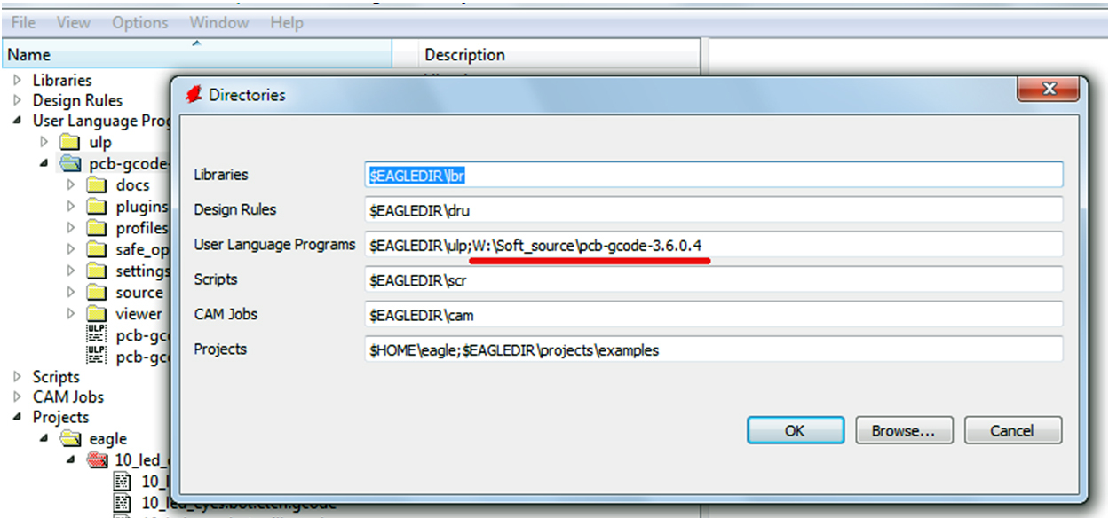
Register the path to the pcb-gcode folder in “Options / Directories / User Language Programs”:
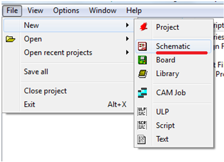
Create a new scheme:
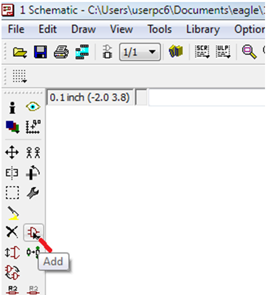
Use the “Add” button to add the required item.
In the “Add” window that opens, we search for the required element and double-click on its name and place it in the scheme.
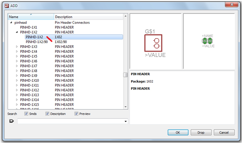
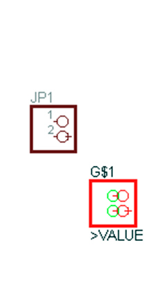
Clicking the left mouse button puts the item. You can put multiple items.
By pressing the “Esc” button we return to the “Add” window.
To exit the "Add" window, click "Cancel".
To connect the elements press the button "Wire"
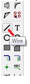
A cross appears. Start and finish the wire (Wire) must be from the contact element
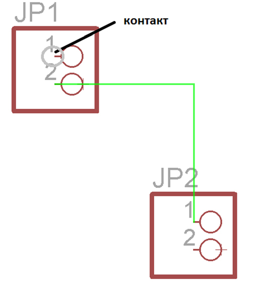
To connect the two wires is the button "Junction"
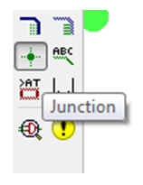
We direct to the intersection of the wires and press the left mouse button
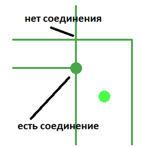
Thus, we create an e-scheme:

Save and click on the «Board» button
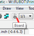
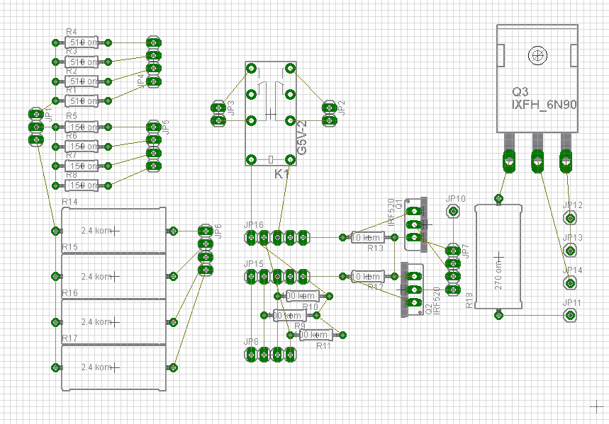
A new board window opens, showing the elements and their connections.
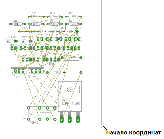
In the manufacture of boards, we will mill the bottom side. In this case, the elements must be placed to the left of the origin.
When preparing gcode, the program inverts X coordinates (horizontally). Then the cutter moves from 0 to the positive side.
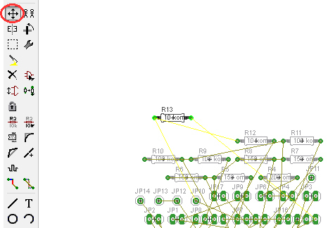
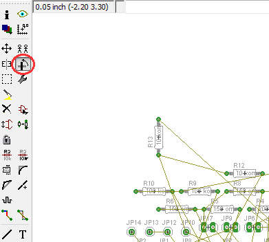
Use the “Rotate” button to rotate elements.
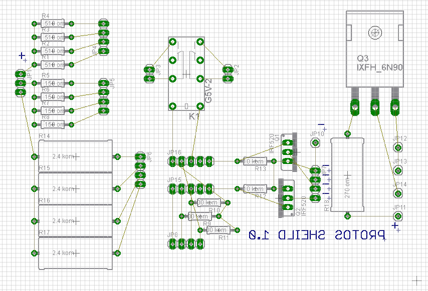
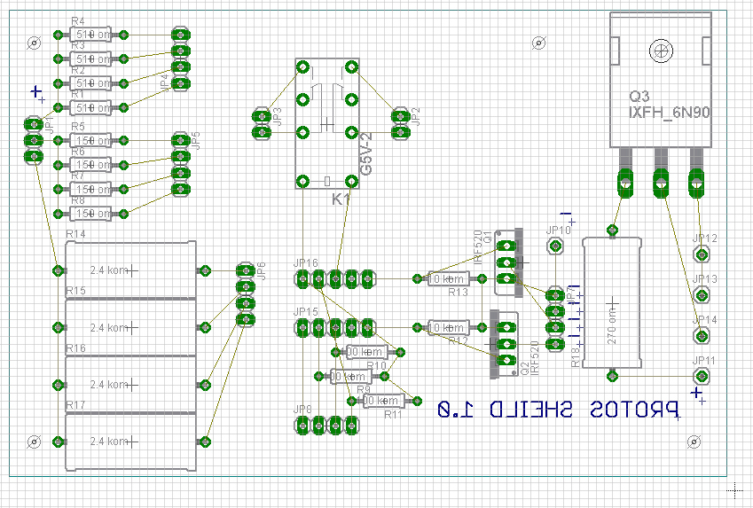
We have items on the board
Add text if necessary with the button "Text"

Add holes with the “Hole” button

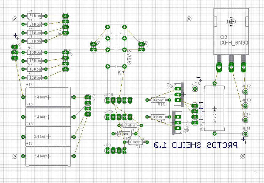
Add the outline of the “Milling” board, for this:
- press the "Wire" button
- select the “Milling” layer
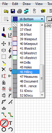
Draw the outline of the board
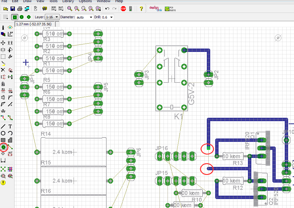
Next, you need to separate the tracks on the board. To do this, click on the button "Route"
Choose track thickness 1,016 and layer "Bottom"
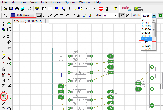
We connect elements by pressing the left mouse button on the beginning of the conductor and on the end.
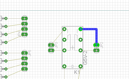
For distributing the track on the upper surface, use the “Via” button. Click on the button and set the transition to the tracks that will be connected by a jumper on top of the board.
We get a ready fee.
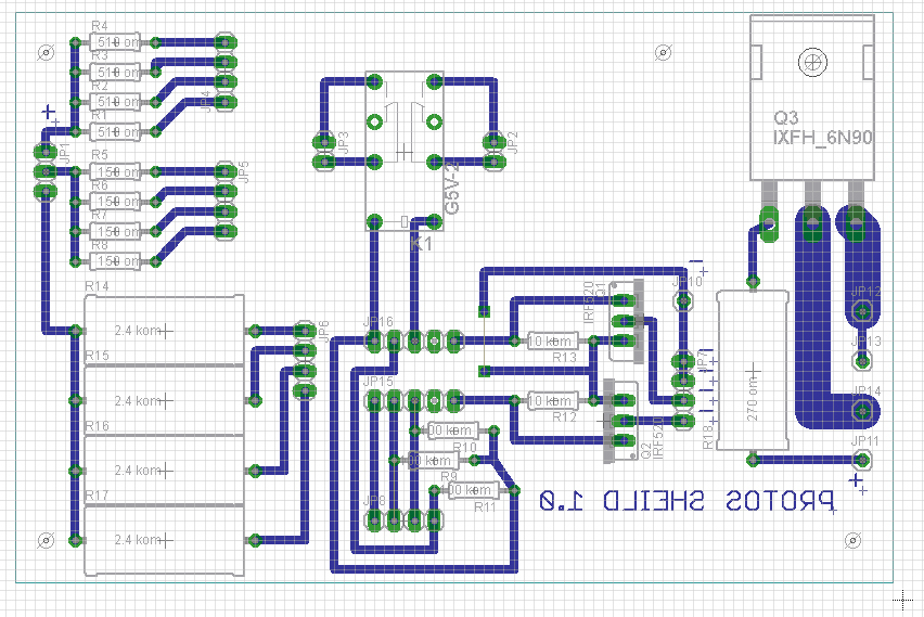
Save the fee.
Now g-code: about him in the next part. For now, prepare your project for production!
Install the equipment!
A bit from the second part:
...
To create g-code in the main Eagle window with the brd file open, right-click on pcb-gcode-setup.ulp and select Run in Board.

The settings window opens.

...
Continued here .
I want to show (just to show) how to quickly organize the production of electronics in DIY.
There will be two parts:
In the first step we will develop and prepare the printed circuit board for production.
In the second step by step we will also make a board.
')
What should be in the home factory of printed circuit boards:
"Project department" -
1. Layout and preparation of the board - semi-commercial Eagle :
2. g-coda preparation program “pcb gcode 3.6.0.4”
This is the source . And on the 3D page of the router it’s the same, but with our settings.
"Production Department" -
1. 3d milling machine .
2. Foiled fiberglass for the board.
Well, now in techno comics. This is a very detailed, on a living example, instructions for designing an electronic board.
Install Eagle, unpack pcb-gcode to any place.
Launch the Eagle.
Register the path to the pcb-gcode folder in “Options / Directories / User Language Programs”:
Create a new scheme:
Use the “Add” button to add the required item.
In the “Add” window that opens, we search for the required element and double-click on its name and place it in the scheme.
Clicking the left mouse button puts the item. You can put multiple items.
By pressing the “Esc” button we return to the “Add” window.
To exit the "Add" window, click "Cancel".
To connect the elements press the button "Wire"
A cross appears. Start and finish the wire (Wire) must be from the contact element
To connect the two wires is the button "Junction"
We direct to the intersection of the wires and press the left mouse button
Thus, we create an e-scheme:
Save and click on the «Board» button
A new board window opens, showing the elements and their connections.
In the manufacture of boards, we will mill the bottom side. In this case, the elements must be placed to the left of the origin.
When preparing gcode, the program inverts X coordinates (horizontally). Then the cutter moves from 0 to the positive side.
Use the “Rotate” button to rotate elements.
We have items on the board
Add text if necessary with the button "Text"
Add holes with the “Hole” button
Add the outline of the “Milling” board, for this:
- press the "Wire" button
- select the “Milling” layer
Draw the outline of the board
Next, you need to separate the tracks on the board. To do this, click on the button "Route"
Choose track thickness 1,016 and layer "Bottom"
We connect elements by pressing the left mouse button on the beginning of the conductor and on the end.
For distributing the track on the upper surface, use the “Via” button. Click on the button and set the transition to the tracks that will be connected by a jumper on top of the board.
We get a ready fee.
Save the fee.
Now g-code: about him in the next part. For now, prepare your project for production!
Install the equipment!
A bit from the second part:
...
To create g-code in the main Eagle window with the brd file open, right-click on pcb-gcode-setup.ulp and select Run in Board.
The settings window opens.
...
Continued here .
Source: https://habr.com/ru/post/367615/
All Articles