How are Z-Wave devices made?
In this article we will explain how Z-Wave devices are created. From the point of view of circuit engineering and programming, the development of a Z-Wave device is not much different from the development of a device based on an Arduino, AVR or PIC. However, there are some nuances in Z-Wave. About them something will be discussed under the cut.
I already wrote about the Z-Wave protocol. Therefore, I will not describe in detail the details of the protocol, but walk along the hardware platform. We will only talk about the last 5th generation of chips and modules that were introduced more than two years ago.
So, from an iron point of view, the chips and Z-Wave modules are the upgraded 8051 core. The chip is made in SoC format, with the following peripherals:
The power of the chip is 2.3–3.6 V. The consumption is about 15 mA in operation mode, 35 mA in receive mode and up to 45 mA in transmit mode. There is also a deep sleep mode with a consumption of 1 μA (awakening from INT1) and WUT (+0.7 μA).
Obviously, many functions and legs intersect and are not available at the same time.
')
Such an abundance of functions in a single chip can significantly reduce the cost of the device being created, since does not require the use of additional microcontrollers. For example, a dimmer, door lock, keychain on batteries, a composite sensor (temperature / humidity / alarm / ...) can be made directly on a Z-Wave microcontroller with a corresponding trim.
But most importantly, a radio transceiver is built into the chip. However, access to it is carried out only through the library Sigma Designs (about this below). Because a lot about him is unknown. We just say that
The minimum “binding” for Z-Wave requires only quartz (included in the modules), antenna matching, several capacitors to stabilize the power supply, and a RESET leg lift. Most Z-Wave devices still require a minimum of 16K of EEPROM (128KB is required for an OTA firmware upgrade).
The chips are manufactured only by Sigma Designs and are licensed by the Japanese Mitsumi. At the moment, the 5th generation of chips is already being produced. A very important aspect in the development of Z-Wave is backward compatibility. And not only at the software level, but also in terms of the form factor and characteristics of the chips. In the line of new modules have pin-to-pin compatible with all previous generations. This allows you to quickly upgrade the devices that are already being manufactured without changing the diagrams and re-routing the boards.
Z-Wave chips are available in two versions:
The following SiP modules are also available, including quartz and minimum strapping for chip operation:
And a series from Mitsumi:
Different module variations have different legs and functions “cut off”. Above, the available functions of the "full" version were indicated, i.e. SD3502 as well as ZM5101 and WML-C84 / C85.
Modules with an integrated SAW filter come in three versions depending on the region (ie, the frequency range): EU / RU / CN / MY / UAE / IN , US / IL and ANZ / BR / JP / TW / HK / KR .
Many of these modules can be purchased even on DigiKey. However, Sigma Designs sells chips only on a large volume by special arrangement.
By the way, some manufacturers make their own modules. For example, Philio Tech makes MD003 (similar to ZM5304 based on SD3503, but without an antenna), MD006 (based on SD3503) and MD008 (something between the ZM5101 and ZM5202 based on SD3502). On KDPV device Philio PST-02 based on MD008.
Sigma Designs also offers a developer kit. This includes:
The whale comes in two parts: common to all and regional (depending on the frequency adopted in your region).
The cost of a whale is from $ 1,500 to $ 3,500, depending on the number of developer boards and programmers and the presence or absence of sensors / performers.
Patents, licenses and NDA do not allow the use of chips and Z-Wave modules for purposes other than Z-Wave. Also, Z-Wave devices cannot be made on a Z-Wave chip (remember, two OSI levels have a patented functionality, which makes it impossible to create a full-fledged Z-Wave stack without the permission of Sigma Designs). This allows Sigma Designs to include the cost of a license (that is, a fee for the development of the protocol, software, utilities, marketing) immediately into the cost of chips and modules.
In order to name your Z-Wave device compatible, you need to get certified (see below).
By the way, according to the license agreement, on each Z-Wave device (usually on the back side; the exception is too compact devices) and the packaging should have the Z-Wave logo. This contributes to the promotion of Z-Wave as a technology brand.

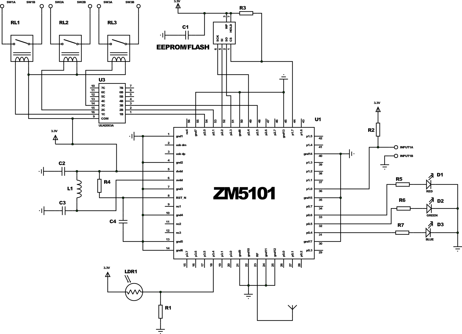
Let's return to the gland. A typical wiring diagram of the ZM5101 is as follows:
In the role of NVM performs SPI EEPROM or FLASH memory at least 16 KB. It is necessary to store data about network nodes, routes, and more. It is possible to create devices without an external EEPROM (in this case, a block of flash memory is used for memory, which reduces the space for the code). EEPROM takes one SPI and one foot for CS . The SPI legs can easily be used as a GPIO or for connecting another SPI Slave, while CS is raised to 3.3 V. The Z-Wave chip is programmed through the same SPI when the RESET is pulled down. This is exactly what a CS brace is needed for (the ZM5101 becomes an SPI Slave, and the second Slave is clearly not needed here).
We will not describe here the part related to antenna and coordination, since this is a topic for a separate scientific work.
All other legs can be used to implement the functionality of the device.
Suppose we want to create a complex device: 3 relays (through the Darlington assembly ULN2003, as the current limit of 20 mA from the foot of the ZM5101 is not enough for an electromagnetic relay, and this will allow the relay to be powered from 5 V or 12 V), one sensor of dry contacts, a sensor illumination (photoresistor) and a beautifully flashing three-color LED. All this can be immediately connected to the Z-Wave chip:
Notice, we still have a bunch of (18) legs! For comparison, her 3 generation of Z-Wave chips and modules (ZM3202) did not allow even such a modest set of peripherals to be connected.
GPIO legs in Z-Wave chips, as in the other 8051, are combined into ports of 8 pieces each. One SFR is responsible for the mode (in / out), the other allows you to enable pull-up for mode in, the third to read / write values. Timer, UART, SPI and other functions are also similar to other 8051: TMOD / THx / TLx, UARTCON / UARTBUF / UARTSTAT, SPIxCON / SPIxDATA / SPISTAT, ... There are so many different registers that in the 5th generation of chips I had to enter the SFRPAGE register to switch between SFR mapping pages on IRAM. The size of 128KB flash memory also required the use of memory banks, which significantly complicates the translated code, filling it with many transitions from bank to bank via COMMON BANK.
In theory, any compiler, for example, SDCC (under the GNU / GPL), could be used to work with the Z-Wave chip. But alas, there is no documentation for all these ports, registers, internal memory mapping, etc. Instead, Sigma Designs chose another way: to deliver a pre-compiled library in binary form (and in fact a set of libraries for different classes of devices: for controllers, for sensors / performers, for gateways). These libraries, compiled for a very specific version of Keil, provide developers with a convenient API for working with hardware (in fact, wrappers for accessing SFR), and for more complex operations with the Z-Wave network: sending commands to other nodes, maintaining the network Z-Wave, route updates and more. This library implements the following levels of the Z-Wave protocol: PHY (directly encoding and decoding at the desired frequency, transmission channel selection, LBT ), MAC (error control, addressing within sight), transport (confirmation, replay) and network (routing, relaying, updating routes, searching for new routes, inclusion into the network, removal from the network).
It is Sigma Designs that deals with compatibility at this level, ensuring protocol development and continuity. The advantages of this approach include the guaranteed compatibility between Z-Wave devices and the simplicity of work at the “top” level, the disadvantages are the low speed of reaction to errors found.
To interact with the Z-Wave network, theuser remains with the developer only simple functions for interacting with other nodes. However, the standard requires tight compatibility and at the levels above: session, representative and applied. These levels are already at the mercy of end device developers. The library allows node A to send a command to node B. In this case, the command must have a strictly defined format described by the Z-Wave protocol in the Command Classes Specification section (about 900 pages of text). This will allow node B to properly parse the command and perform the appropriate action with the periphery.
Z-Wave libraries are made in a “callback” format. The starting point (main) is in the library, and control to the user is transferred only at certain moments:
In all functions that require time and working "asynchronously", you can also transfer a callback. For example, when calling the package sending function, you can specify a handler that will receive the sending status (delivered, not delivered, and error code). The timers subsystem is similarly implemented (besides the exact ones based on TIMER1 and GPT): you can run up to 5 software timers that work in 10 ms increments (TIMER0 cannot be used, it is used by the library for internal needs and software timers). All this facilitates the work of programmers manufacturer of the end device.
Together with the Z-Wave libraries, a huge number of structures and constants predetermined in the header files are also supplied that correspond to the standard, which greatly simplifies development. Sigma Designs also supplies two dozen examples that implement simple devices, for example, a relay or a binary sensor or a door lock, with the minimum functionality necessary for operation and certification of Z-Wave Plus . It's funny, but more than half of Z-Wave devices manufactured in the Middle Kingdom are based on these examples without a single modified line, except for the ManufacturerId, ProductId, ProductTypeId identifiers (we are talking about the manufacturer’s identifiers, series and models; for certification they must be unique, so if if not this requirement, they would not differ at all;)
The combination of all the headers, libraries and sample code is Z-Wave SDK or ZDK. ZDK is distributed under the NDA. Usually, NDA is signed when you purchase DevKit.
As mentioned earlier, in order to develop our own device, we will need Keil C51 . It costs about 2600 Euro. But this is not all waste, we are waiting for another stage.
In addition to programming the logic of working with peripherals, you must declare a list of supported classes of commands for the device being created in NIF , as well as implement the declared classes of commands (for more details about command classes, see this article ). In fact, it comes down to writing code that processes all possible commands of all supported classes.
For example, for the Switch Binary class (ID 0x25), you must process the Set command (25 01) by turning on the relay or LED or something else, the Get command (25 02), responding to it with the Report command (25 03 xx), where xx = 00 or FF, depending on the current state of the relay, light bulb or whatever you have there.
For our example of a “complex” device, it will look something like this.
Obviously, all devices must process these commands more or less equally. 3 years ago we pretty well template our code, creating a common code base for our devices. Many of our devices differ only in a single .h file. More complex have a couple of sishnikov for specials. functional. With the release of the 5th generation of chips, Sigma Designs has done something similar, so the code for the examples is easy to adapt to fit your needs.
After you have invented a device, made a prototype, wrote firmware for it, you need to certify your device. The certification process is required to verify that your device complies with the Z-Wave protocol. It consists of two parts: Technical Certification (verification of the device itself) and Market Certification, which also verifies the documentation (mentioning the key Z-Wave terms), the presence and correctness of using the Z-Wave logo or Z-Wave Plus.
Z-Wave certification is carried out by one of three certificate authorities: Pepper One in Germany, BuLogics in the USA or at Sigma Designs itself. Before certification, it is required to undergo the certification process independently (self-certification), which allows you to immediately detect and eliminate many errors, as well as reduce the likelihood of file certification. To do this, there is a special CTT utility available to the full members of the Z-Wave Alliance. She is used by certifiers. There is also a certification form (depending on the device in it from 100 to 300 points), on which you need to describe the device. According to this form will be certified. For all items there is a detailed description of how it is tested and what is expected from the device. It is worth noting that the whole process is fairly transparent - it is clear in advance what they will check and how (if all the docks are read in advance;)
Certification is a laborious and laborious process. Certification also costs money: depending on the complexity of the device from $ 3,000 to $ 5,500. It's all about how the exams in the traffic police: allowed some reasonable number of fail'ov that need to be eliminated within a month (the so-called ad-hoc period). If there are more files or could not be fixed, then re-certification with a new payment will be required. This is a good incentive to test your devices well. Personally, we zafaililis only once, but he strongly knocked out our pride.
Significant changes in device functionality or behavior on the Z-Wave network require re-certification (re-certification costs half the price). Often one device without change is sold in different versions and colors. In this case, you only need to repeat the Market Certification (for free).
Again, using the example of our “complex” device, CTT will see that we in the SwitchMultilevel class do not process the StartLevelChange and StopLevelChange commands necessary for dimming. If we do not fix it, then our device will not pass certification. (We just did not want to increase so a terrible piece of handler code).
Also note that certification (and CTT) are available only to full members of the Z-Wave Allianas (Full or Principal Member, but not the Affiliate Member). This is another $ 4,000 per year .
Immediately, I note that there is no JTAG or other debugging tools in the Z-Wave chip! This makes the life of the developers terrible and unbearable. Therefore, often complex code is tested and debugged first on any chip of the 8051 family from, for example, Silicon Labs, which did not skimp on a normal JTAG or C2, conveniently integrated into the built-in debugger in Keil. We also test parts of the code by compiling it on Linux with gcc and running various tests (for example, we are testing our packet queue engine for sending to devices). This makes it impossible to catch overflows typical of the microcontroller's architecture itself (for example, getting out of a small stack, lack of registers for recursive or simply deeply nested function calls) or debugging the code associated with SFR or hardware of the chip, but basic “platform-independent” problems easy to catch. Often, you have to pick the ASM code ( d52 is our everything!), And also use the convenient tools of Keil itself with map files.
Otherwise, you have to settle for debugging via I2C, SPI or UART (which works for simple problems when stack or memory corruption does not occur from distant pieces of code).
A separate exercise is to create battery-powered devices — to reduce power consumption, you need to write high-quality code that takes into account long operation time (ADC, radio, access to EEPROM) and the location of variables (256 bytes of XRAM are powered even in deep sleep mode, allowing Wake up does not read a slow EEPROM, but quickly make a decision and go to sleep further).
When creating more complex devices that require a lot of legs, it is necessary to use several chips communicating via UART, SPI or I2C. In this case, part of the functionality of working with the periphery (or all) goes to the second chip. Very convenient is the use of more advanced in terms of the capabilities of the periphery and power consumption Atmel (with reduced frequency) or Cortex. Such an approach allows using the Z-Wave chip only as a “modem”.
A special case of this approach is the use of a Z-Wave chip in conjunction with another CPU with a full-fledged OS (for example, a PC or Raspberry Pi). In order not to push manufacturers to reinvent the wheel, Sigma Designs proposed its own standard for exchanging data between the CPU and the Z-Wave UART chip, which is called the Z-Wave Serial API. In this case, the firmware implements UART data exchange, displaying almost 1: 1 all commands available to the developer on the Serial API commands from the CPU, and returning the values and callback via commands to the CPU. An example of such firmware is available in the ZDK and is available to all developers. This approach made it possible to create a “market” of Z-Wave USB sticks separately from the “market” of software for them: many manufacturers offer interchangeable sticks, while software manufacturers create software that works with any stick. This kind of software called Z-Wave PC Controller is included in ZDK (available in sursu).
In addition, this approach contributes to the spread of technology: the manufacturer of a TV set-top box or router, having created a solution based on a third-party Z-Wave USB stick, with increasing sales may decide to order a PCB lot with an installed Z-Wave module, thereby cheapening the solution. In this case, the ZM5304 module is most often used (ZDK has a firmware for it that implements the Serial API).
However, some companies that produce both hardware and software (we treat them with our UZB sticks, RaZberry expansion cards and our Z-Way software) prefer to “tie” software to sticks, since in this case there is less support (we, for example, , we eliminate many problems of the Sigma Designs code and supplement it with our extensions) and it is easier to collect money for software (the cost is already included in the stick). Others (for example, Merten) generally created their own data exchange format different from the Z-Wave Serial API.
For each region are assigned several FAEs from Sigma Designs. They help new manufacturers get started with Z-Wave, accept bug reports and help with controversial situations during the certification process.
Z-Wave Alliance is also actively involved in the life of manufacturers, offering not only testing utilities and training materials. Several times a year in different parts of the world, the Alliance gathers developers at the UnPlug Fest conference to share experiences and test their devices with other participants. FAE Sigma Designs also participate in these events. UnPlug Fest is always accompanied by a two-day training for new developers.
The Z-Wave Alliance also organizes the Interoperability Lab in New Jersey, USA, where you can test your devices for compatibility as well as in a special radio lab.
In addition, the Alliance has Z-Wave protocol development working groups. All developers can offer their ideas and influence the functionality of the next versions of all classes of commands and the protocol as a whole.
More information is available on the Z-Wave Alliance website.
Let us return to the issue of economics and calculate what it will cost us per device. I will do it very roughly and assessed - do not judge strictly. Detailed financial analysis is not the purpose of this article. For evaluation, I even put € = $ (yes brokers will forgive me).
Imagine that we are going to release 5,000 devices of some type. The unit price will consist of BOM and development costs.
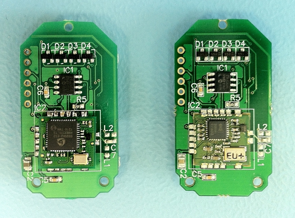 Let us forget about our “complex” device and talk about, for example, a simple key fob (on the left, the board of our key fob in the 5th generation, on the right in 3 plots ). A rough calculation shows that the components (except for the Z-Wave chip) and the PCB with the assembly cost about 7 bucks (talking about the small-scale production of our party, and not about a million Chinese keyfobs). The ZM5202 module costs 5 more (analogs cost about 2 bucks, i.e., about 3 went for the Z-Wave license). Another body for 1 bucks (so help Alibaba!). Total 13.
Now let's calculate the cost of developing the firmware: 2600 (Keil) + 2500 (DevKit / ZDK) + 4000 (Alliance membership for a year) + 3500 (certification) ≈ 2.5 bucks per device. And with the production of several models, the first three items will be distributed over all types of devices, i.e. the price will fall significantly.
Also worth considering the work of programmers. In our experience, on the first device they will “devour” at least 10 person – months, or even more. That for the first device will result in 2-4 bucks (for subsequent devices it will be 2-3 times less due to the accumulation of experience).
Thus, your first 5000 (very simple) devices will cost you 19.5 bucks. Add VAT, transportation, duties (for imports), certification, margin for yourself and channel partners, minimal marketing, and we getthree ends for about 60 bucks. With experience and growth in production, this figure will be closer to 15 bucks, i.e. closer to 45 in retail. This is the retail price of the device here. This is the question of how much it costs, and why.
Also note that the first experienced certified sample will cost at least 20 000 bucks. Less well, in no way newcomers fail.
Can I make it cheaper on a proprietary protocol and some kind of chip from TI or Silicon Labs? Not a fact, if we are not talking about a collective farm on our knees, but about a serial device with good support. Yes, Z-Wave is 20% –30% more expensive, but it is often justified.
As you can see, the process of creating your own devices based on the Z-Wave protocol does not hide any mysteries and is completely accessible to any IT company familiar with microcontrollers. Thanks to the SoC format, many devices can be made on a Z-Wave chip and a small number of additional components. Yes, you have to read about 2000 pages of specification and go through certification.
Is it worth it to get into all this, and why do you need Z-Wave? If you want to create only a controlled light bulb and a motion sensor, and even cheaper, then Z-Wave will be a burden to you. But if you want to create complete components of a smart home, then you better “fit” into an existing well-developed protocol, such as Z-Wave. After all, few companies in the market are able to independently produce a line of 30–50 devices for various purposes: from keyfobs and relays to thermostats and door locks. Having joined the popular protocol, you can increase sales of your device by fitting it into the existing ecosystem of smart home devices.
You are a geek, not willing to pay a lot of money and study the insides of Z-Wave in such detail? But the finished device does not suit you? Then as advertising we will tell about one our new device. Meet the Z-Uno!

About Z-Uno we will write a separate article (link from the future: geektimes.ru/post/268980 ). In short, this is a small motherboard based on the ZM5101. We have brought out almost all the legs of this module for you. This device has a special firmware that allows you to load custom code written in the Arduino IDE environment in the usual for “Arduinschikov” language. We have supplemented the “syntax” of the Arduino with our macros, which allow us to describe the Z-Wave functions of the device (up to 10 functions) and determine what to send for each function. Thus, Z-Uno is an Arduino clone (with some reservations, this is not Atmel, but 8051) with built-in support for Z-Wave. Wait for the next article or read on z-uno.z-wave.me .
I already wrote about the Z-Wave protocol. Therefore, I will not describe in detail the details of the protocol, but walk along the hardware platform. We will only talk about the last 5th generation of chips and modules that were introduced more than two years ago.
Iron
So, from an iron point of view, the chips and Z-Wave modules are the upgraded 8051 core. The chip is made in SoC format, with the following peripherals:
- 128 KB of flash memory for your code
- 16 KB of RAM (XRAM) and 256 bytes (IRAM), where SFR registers are mapped,
- 256 bytes of NVR (crystal calibration data and lock bit are also stored there),
- 30 GPIO,
- 2 UART,
- 2 SPI (Master and Master / Slave),
- 1 USB (Serial only),
- 4 ADC 12/8 bits,
- 1 scanner with 88 keys (with the ability to scan in deep sleep mode),
- 1 TRIAC controller oscillator with ZEROX detector ,
- 5 PWM with 16 bit resolution
- 4 IR controllers and 1 IR decoder for training,
- bootloader (enabled by pin RESET or from code by writing to the corresponding SFR register) for flashing by SPI or UART, as well as the ability to reprogram yourself (rewriting flash memory is used for OTA flashing),
- Built-in crypto accelerator for 128-bit AES encryption,
- power monitor (to assess battery charge).
The power of the chip is 2.3–3.6 V. The consumption is about 15 mA in operation mode, 35 mA in receive mode and up to 45 mA in transmit mode. There is also a deep sleep mode with a consumption of 1 μA (awakening from INT1) and WUT (+0.7 μA).
Obviously, many functions and legs intersect and are not available at the same time.
')
Such an abundance of functions in a single chip can significantly reduce the cost of the device being created, since does not require the use of additional microcontrollers. For example, a dimmer, door lock, keychain on batteries, a composite sensor (temperature / humidity / alarm / ...) can be made directly on a Z-Wave microcontroller with a corresponding trim.
But most importantly, a radio transceiver is built into the chip. However, access to it is carried out only through the library Sigma Designs (about this below). Because a lot about him is unknown. We just say that
- sensitivity at the operating frequency of Z-Wave is -104dBm,
- 5dBm output power
- working range is 850–940 MHz. (We are sure that it is more, but the description of the RF part is completely absent, therefore there is no available information about other uses of the radio transceiver. Obviously, this is a typical SDR chip, and Sigma Designs did not invent the bicycle here).
The minimum “binding” for Z-Wave requires only quartz (included in the modules), antenna matching, several capacitors to stabilize the power supply, and a RESET leg lift. Most Z-Wave devices still require a minimum of 16K of EEPROM (128KB is required for an OTA firmware upgrade).
Suppliers
The chips are manufactured only by Sigma Designs and are licensed by the Japanese Mitsumi. At the moment, the 5th generation of chips is already being produced. A very important aspect in the development of Z-Wave is backward compatibility. And not only at the software level, but also in terms of the form factor and characteristics of the chips. In the line of new modules have pin-to-pin compatible with all previous generations. This allows you to quickly upgrade the devices that are already being manufactured without changing the diagrams and re-routing the boards.
Available chip options
Z-Wave chips are available in two versions:
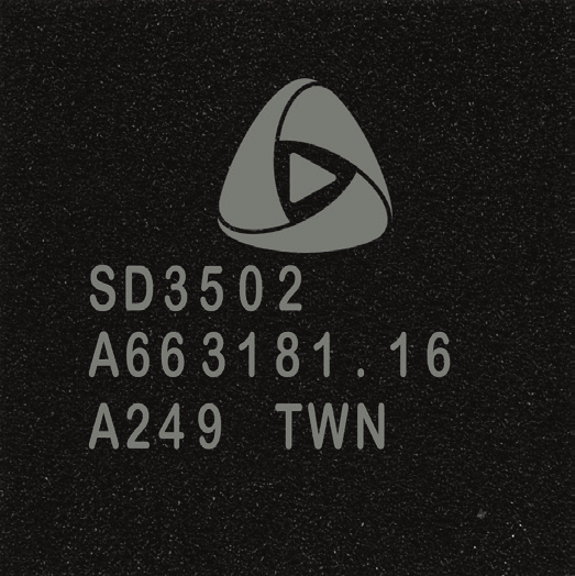 | SD3502 , 48-QFN 7x7 mm, |
| SD3503 , 32-QFN 5x5 mm (trimmed version compared to SD3502). |
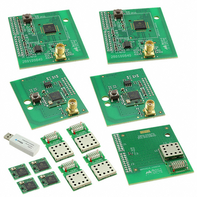
The following SiP modules are also available, including quartz and minimum strapping for chip operation:
 | ZM5101 , 56-QFN 8x8 mm, compatible with ZM4101 ( 4th generation), |
 | ZM5202 , PCB 12.5x13.6 mm, based on SD3502, compatible with ZM3102 (3 of its generation), |
 | ZM5304 , PCB 27x15.2 mm, based on SD3503, includes EEPROM memory, SAW filter, spiral antenna and protective screen (designed for “modems”, i.e. for Z-Wave controllers), |
And a series from Mitsumi:
 | WML-C84 , 56-QFN 8x8 mm, full analog ZM5101, |
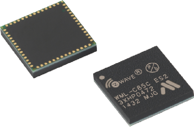 | WML-C85, 56-QFN 8x8 mm, compared to C84, has an integrated SAW filter, |
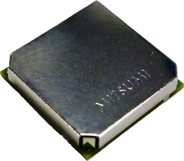 | WML-C86, 56-QFN 15x15 mm, integrated SAW filter and EEPROM, increased TX power and RX sensitivity, protective screen, |
| WML-C87, 56-QFN 15x15 mm, built-in SAW filter and EEPROM, increased sensitivity RX, protective screen. |
Different module variations have different legs and functions “cut off”. Above, the available functions of the "full" version were indicated, i.e. SD3502 as well as ZM5101 and WML-C84 / C85.
Modules with an integrated SAW filter come in three versions depending on the region (ie, the frequency range): EU / RU / CN / MY / UAE / IN , US / IL and ANZ / BR / JP / TW / HK / KR .
Many of these modules can be purchased even on DigiKey. However, Sigma Designs sells chips only on a large volume by special arrangement.
By the way, some manufacturers make their own modules. For example, Philio Tech makes MD003 (similar to ZM5304 based on SD3503, but without an antenna), MD006 (based on SD3503) and MD008 (something between the ZM5101 and ZM5202 based on SD3502). On KDPV device Philio PST-02 based on MD008.
Devkit
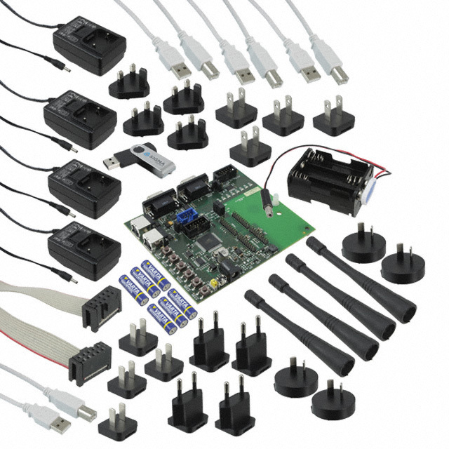
Sigma Designs also offers a developer kit. This includes:
- a set of chips of different form factors, including on developer boards, which are installed directly on the programmer (very convenient for prototyping),
- programmer (Z-Wave chips are programmed by a special programmer - there is a choice on the market: this one from Sigma Designs, more suitable for production from us, Z-Wave.Me and completely industrial from Equinox ),
- sniffer (for wiretapping the ether - just a necessary thing when debugging devices),
- USB stick for central controller,
- several sensors and performers
- Windows software for the programmer, sniffer, controller, as well as all sorts of auxiliary utilities,
- Z-Wave SDK to create firmware for Z-Wave chips (see below),
- all sorts of wires and power supplies.
The whale comes in two parts: common to all and regional (depending on the frequency adopted in your region).
The cost of a whale is from $ 1,500 to $ 3,500, depending on the number of developer boards and programmers and the presence or absence of sensors / performers.
Legal side
Patents, licenses and NDA do not allow the use of chips and Z-Wave modules for purposes other than Z-Wave. Also, Z-Wave devices cannot be made on a Z-Wave chip (remember, two OSI levels have a patented functionality, which makes it impossible to create a full-fledged Z-Wave stack without the permission of Sigma Designs). This allows Sigma Designs to include the cost of a license (that is, a fee for the development of the protocol, software, utilities, marketing) immediately into the cost of chips and modules.
In order to name your Z-Wave device compatible, you need to get certified (see below).
By the way, according to the license agreement, on each Z-Wave device (usually on the back side; the exception is too compact devices) and the packaging should have the Z-Wave logo. This contributes to the promotion of Z-Wave as a technology brand.
Typical layout
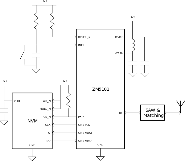
Let's return to the gland. A typical wiring diagram of the ZM5101 is as follows:
In the role of NVM performs SPI EEPROM or FLASH memory at least 16 KB. It is necessary to store data about network nodes, routes, and more. It is possible to create devices without an external EEPROM (in this case, a block of flash memory is used for memory, which reduces the space for the code). EEPROM takes one SPI and one foot for CS . The SPI legs can easily be used as a GPIO or for connecting another SPI Slave, while CS is raised to 3.3 V. The Z-Wave chip is programmed through the same SPI when the RESET is pulled down. This is exactly what a CS brace is needed for (the ZM5101 becomes an SPI Slave, and the second Slave is clearly not needed here).
We will not describe here the part related to antenna and coordination, since this is a topic for a separate scientific work.
All other legs can be used to implement the functionality of the device.
Suppose we want to create a complex device: 3 relays (through the Darlington assembly ULN2003, as the current limit of 20 mA from the foot of the ZM5101 is not enough for an electromagnetic relay, and this will allow the relay to be powered from 5 V or 12 V), one sensor of dry contacts, a sensor illumination (photoresistor) and a beautifully flashing three-color LED. All this can be immediately connected to the Z-Wave chip:
- We will put 3 inputs of the relay on GPIO, for example, P2.0, P2.1, P2.5 (legs P2.2 – P2.4 occupies an EEPROM connected via SPI)
- the dry contact sensor is connected to INT0 (P1.0), INT1 (P1.1), or any other GPIO leg, if simple polling is planned, but not an ISR processor,
- The illumination sensor in the divider is connected to ADC0, it is also P3.4 (the second arm must be selected so that all possible values are placed in the range of 0–3.3V),
- Our three-color LED will be connected to PWM0–2 (P0.4 – P0.6), which will allow you to smoothly change colors in the mode of New Year's garland.
Notice, we still have a bunch of (18) legs! For comparison, her 3 generation of Z-Wave chips and modules (ZM3202) did not allow even such a modest set of peripherals to be connected.
Firmware
GPIO legs in Z-Wave chips, as in the other 8051, are combined into ports of 8 pieces each. One SFR is responsible for the mode (in / out), the other allows you to enable pull-up for mode in, the third to read / write values. Timer, UART, SPI and other functions are also similar to other 8051: TMOD / THx / TLx, UARTCON / UARTBUF / UARTSTAT, SPIxCON / SPIxDATA / SPISTAT, ... There are so many different registers that in the 5th generation of chips I had to enter the SFRPAGE register to switch between SFR mapping pages on IRAM. The size of 128KB flash memory also required the use of memory banks, which significantly complicates the translated code, filling it with many transitions from bank to bank via COMMON BANK.
In theory, any compiler, for example, SDCC (under the GNU / GPL), could be used to work with the Z-Wave chip. But alas, there is no documentation for all these ports, registers, internal memory mapping, etc. Instead, Sigma Designs chose another way: to deliver a pre-compiled library in binary form (and in fact a set of libraries for different classes of devices: for controllers, for sensors / performers, for gateways). These libraries, compiled for a very specific version of Keil, provide developers with a convenient API for working with hardware (in fact, wrappers for accessing SFR), and for more complex operations with the Z-Wave network: sending commands to other nodes, maintaining the network Z-Wave, route updates and more. This library implements the following levels of the Z-Wave protocol: PHY (directly encoding and decoding at the desired frequency, transmission channel selection, LBT ), MAC (error control, addressing within sight), transport (confirmation, replay) and network (routing, relaying, updating routes, searching for new routes, inclusion into the network, removal from the network).
It is Sigma Designs that deals with compatibility at this level, ensuring protocol development and continuity. The advantages of this approach include the guaranteed compatibility between Z-Wave devices and the simplicity of work at the “top” level, the disadvantages are the low speed of reaction to errors found.
To interact with the Z-Wave network, the
Z-Wave libraries are made in a “callback” format. The starting point (main) is in the library, and control to the user is transferred only at certain moments:
- at the start (two entry points - immediately after the start of the chip to initialize the hardware and later, when the library was initialized and you can already use some of its functions - the analog setup () in Arduino,
- when the library is not busy (receiving / sending data, sending packets to other network nodes, responding to controller requests) - here you can poll buttons, measure the value on the ADC, etc. - analog loop () in Arduino,
- when the command is received (where we are the recipient, the CRC agreed and the sender from our network).
In all functions that require time and working "asynchronously", you can also transfer a callback. For example, when calling the package sending function, you can specify a handler that will receive the sending status (delivered, not delivered, and error code). The timers subsystem is similarly implemented (besides the exact ones based on TIMER1 and GPT): you can run up to 5 software timers that work in 10 ms increments (TIMER0 cannot be used, it is used by the library for internal needs and software timers). All this facilitates the work of programmers manufacturer of the end device.
Together with the Z-Wave libraries, a huge number of structures and constants predetermined in the header files are also supplied that correspond to the standard, which greatly simplifies development. Sigma Designs also supplies two dozen examples that implement simple devices, for example, a relay or a binary sensor or a door lock, with the minimum functionality necessary for operation and certification of Z-Wave Plus . It's funny, but more than half of Z-Wave devices manufactured in the Middle Kingdom are based on these examples without a single modified line, except for the ManufacturerId, ProductId, ProductTypeId identifiers (we are talking about the manufacturer’s identifiers, series and models; for certification they must be unique, so if if not this requirement, they would not differ at all;)
The combination of all the headers, libraries and sample code is Z-Wave SDK or ZDK. ZDK is distributed under the NDA. Usually, NDA is signed when you purchase DevKit.
As mentioned earlier, in order to develop our own device, we will need Keil C51 . It costs about 2600 Euro. But this is not all waste, we are waiting for another stage.
Team Classes and NIFs
In addition to programming the logic of working with peripherals, you must declare a list of supported classes of commands for the device being created in NIF , as well as implement the declared classes of commands (for more details about command classes, see this article ). In fact, it comes down to writing code that processes all possible commands of all supported classes.
For example, for the Switch Binary class (ID 0x25), you must process the Set command (25 01) by turning on the relay or LED or something else, the Get command (25 02), responding to it with the Report command (25 03 xx), where xx = 00 or FF, depending on the current state of the relay, light bulb or whatever you have there.
For our example of a “complex” device, it will look something like this.
Pseudocode handler
NIF will contain 0x25 (SwitchBinary), 0x26 (SwitchMultilevel), 0x30 (SensorBinary), 0x31 (SensorMultilevel), 0x60 (MultiChannel) and a dozen other service classes needed only for service tasks and settings.
As you can see, we processed 8 channels of different types here.
(This is a very simplified code for understanding, but the basic idea is preserved. Of course, we are not writing this way - we just decided not to scare you and NDA once again not to break. Details here .)
switch (pCmd[0]) { case COMMAND_CLASS_MULTI_CHANNEL: switch (pCmd[1]) { case MULTI_CHANNEL_CMD_ENCAP: switch (pCmd[4]) { case COMMAND_CLASS_MULTI_SWITCH_BINARY: // if (pCmd[3] == 1) { switch(pCmd[5]) { case SWITCH_BINARY_SET: pin_set(P2_0, pCmd[6] ? 1 : 0); break; case SWITCH_BINARY_GET: // : ; , ; ; ; ; ... SendMultiChannelReport(srcNodeId, pCmd[2], pCmd[3], COMMAND_CLASS_MULTI_SWITCH_BINARY, SWITCH_BINARY_REPORT, pin_get(P2_0)); break; } } if (pCmd[3] == 2) { switch(pCmd[5]) { case SWITCH_BINARY_SET: pin_set(P2_1, pCmd[6] ? 1 : 0); break; case SWITCH_BINARY_GET: SendMultiChannelReport(srcNodeId, pCmd[2], pCmd[3], COMMAND_CLASS_MULTI_SWITCH_BINARY, SWITCH_BINARY_REPORT, pin_get(P2_1)); break; } } if (pCmd[3] == 3) { switch(pCmd[5]) { case SWITCH_BINARY_SET: pin_set(P2_5, pCmd[6] ? 1 : 0); break; case SWITCH_BINARY_GET: SendMultiChannelReport(srcNodeId, pCmd[2], pCmd[3], COMMAND_CLASS_MULTI_SWITCH_BINARY, SWITCH_BINARY_REPORT, pin_get(P2_5)); break; } } break; case COMMAND_CLASS_MULTI_SENSOR_BINARY: if (pCmd[3] == 4) { switch(pCmd[5]) { case SENSOR_BINARY_GET: SendMultiChannelReport(srcNodeId, pCmd[2], pCmd[3], COMMAND_CLASS_MULTI_SENSOR_BINARY, SENSOR_BINARY_REPORT, SENSOR_BINARY_TYPE_GENERAL_PURPOSE /* */, pin_get(P1_0)); break; } } case COMMAND_CLASS_MULTI_SENSOR_MULTILEVEL: if (pCmd[3] == 5) { switch(pCmd[5]) { case SENSOR_MULTILEVEL_GET: SendMultiChannelReport(srcNodeId, pCmd[2], pCmd[3], COMMAND_CLASS_MULTI_SENSOR_MULTILEVEL, SENSOR_MULTILEVEL_REPORT, SENSOR_MULTILEVEL_TYPE_LUMINESENCE /* */, 0 /* % */, analog_get(P3_4)); break; } } case COMMAND_CLASS_MULTI_SWITCH_MULTILEVEL: if (pCmd[3] == 6) { switch(pCmd[5]) { case SWITCH_MULTILEVEL_SET: pwm_set(P0_4, pCmd[6] > 99? 99 : pCmd[6]); break; case SWITCH_MULTILEVEL_GET: SendMultiChannelReport(srcNodeId, pCmd[2], pCmd[3], COMMAND_CLASS_MULTI_SWITCH_MULTILEVEL, SWITCH_MULTILEVEL_REPORT, pwm_current(P0_4)); break; } } case COMMAND_CLASS_MULTI_SWITCH_MULTILEVEL: if (pCmd[3] == 7) { switch(pCmd[5]) { case SWITCH_MULTILEVEL_SET: pwm_set(P0_5, pCmd[6] > 99? 99 : pCmd[6]); break; case SWITCH_MULTILEVEL_GET: SendMultiChannelReport(srcNodeId, pCmd[2], pCmd[3], COMMAND_CLASS_MULTI_SWITCH_MULTILEVEL, SWITCH_MULTILEVEL_REPORT, pwm_current(P0_5)); break; } } case COMMAND_CLASS_MULTI_SWITCH_MULTILEVEL: if (pCmd[3] == 8) { switch(pCmd[5]) { case SWITCH_MULTILEVEL_SET: pwm_set(P0_6, pCmd[6] > 99? 99 : pCmd[6]); break; case SWITCH_MULTILEVEL_GET: SendMultiChannelReport(srcNodeId, pCmd[2], pCmd[3], COMMAND_CLASS_MULTI_SWITCH_MULTILEVEL, SWITCH_MULTILEVEL_REPORT, pwm_current(P0_6)); break; } } break; } } } As you can see, we processed 8 channels of different types here.
(This is a very simplified code for understanding, but the basic idea is preserved. Of course, we are not writing this way - we just decided not to scare you and NDA once again not to break. Details here .)
Obviously, all devices must process these commands more or less equally. 3 years ago we pretty well template our code, creating a common code base for our devices. Many of our devices differ only in a single .h file. More complex have a couple of sishnikov for specials. functional. With the release of the 5th generation of chips, Sigma Designs has done something similar, so the code for the examples is easy to adapt to fit your needs.
Certification
After you have invented a device, made a prototype, wrote firmware for it, you need to certify your device. The certification process is required to verify that your device complies with the Z-Wave protocol. It consists of two parts: Technical Certification (verification of the device itself) and Market Certification, which also verifies the documentation (mentioning the key Z-Wave terms), the presence and correctness of using the Z-Wave logo or Z-Wave Plus.
Z-Wave certification is carried out by one of three certificate authorities: Pepper One in Germany, BuLogics in the USA or at Sigma Designs itself. Before certification, it is required to undergo the certification process independently (self-certification), which allows you to immediately detect and eliminate many errors, as well as reduce the likelihood of file certification. To do this, there is a special CTT utility available to the full members of the Z-Wave Alliance. She is used by certifiers. There is also a certification form (depending on the device in it from 100 to 300 points), on which you need to describe the device. According to this form will be certified. For all items there is a detailed description of how it is tested and what is expected from the device. It is worth noting that the whole process is fairly transparent - it is clear in advance what they will check and how (if all the docks are read in advance;)
Certification is a laborious and laborious process. Certification also costs money: depending on the complexity of the device from $ 3,000 to $ 5,500. It's all about how the exams in the traffic police: allowed some reasonable number of fail'ov that need to be eliminated within a month (the so-called ad-hoc period). If there are more files or could not be fixed, then re-certification with a new payment will be required. This is a good incentive to test your devices well. Personally, we zafaililis only once, but he strongly knocked out our pride.
Significant changes in device functionality or behavior on the Z-Wave network require re-certification (re-certification costs half the price). Often one device without change is sold in different versions and colors. In this case, you only need to repeat the Market Certification (for free).
Again, using the example of our “complex” device, CTT will see that we in the SwitchMultilevel class do not process the StartLevelChange and StopLevelChange commands necessary for dimming. If we do not fix it, then our device will not pass certification. (We just did not want to increase so a terrible piece of handler code).
Also note that certification (and CTT) are available only to full members of the Z-Wave Allianas (Full or Principal Member, but not the Affiliate Member). This is another $ 4,000 per year .
Debugging
Immediately, I note that there is no JTAG or other debugging tools in the Z-Wave chip! This makes the life of the developers terrible and unbearable. Therefore, often complex code is tested and debugged first on any chip of the 8051 family from, for example, Silicon Labs, which did not skimp on a normal JTAG or C2, conveniently integrated into the built-in debugger in Keil. We also test parts of the code by compiling it on Linux with gcc and running various tests (for example, we are testing our packet queue engine for sending to devices). This makes it impossible to catch overflows typical of the microcontroller's architecture itself (for example, getting out of a small stack, lack of registers for recursive or simply deeply nested function calls) or debugging the code associated with SFR or hardware of the chip, but basic “platform-independent” problems easy to catch. Often, you have to pick the ASM code ( d52 is our everything!), And also use the convenient tools of Keil itself with map files.
Otherwise, you have to settle for debugging via I2C, SPI or UART (which works for simple problems when stack or memory corruption does not occur from distant pieces of code).
A separate exercise is to create battery-powered devices — to reduce power consumption, you need to write high-quality code that takes into account long operation time (ADC, radio, access to EEPROM) and the location of variables (256 bytes of XRAM are powered even in deep sleep mode, allowing Wake up does not read a slow EEPROM, but quickly make a decision and go to sleep further).
Sophisticated devices
When creating more complex devices that require a lot of legs, it is necessary to use several chips communicating via UART, SPI or I2C. In this case, part of the functionality of working with the periphery (or all) goes to the second chip. Very convenient is the use of more advanced in terms of the capabilities of the periphery and power consumption Atmel (with reduced frequency) or Cortex. Such an approach allows using the Z-Wave chip only as a “modem”.
Z-Wave Serial API
A special case of this approach is the use of a Z-Wave chip in conjunction with another CPU with a full-fledged OS (for example, a PC or Raspberry Pi). In order not to push manufacturers to reinvent the wheel, Sigma Designs proposed its own standard for exchanging data between the CPU and the Z-Wave UART chip, which is called the Z-Wave Serial API. In this case, the firmware implements UART data exchange, displaying almost 1: 1 all commands available to the developer on the Serial API commands from the CPU, and returning the values and callback via commands to the CPU. An example of such firmware is available in the ZDK and is available to all developers.
This approach made it possible to create a “market” of Z-Wave USB sticks separately from the “market” of software for them: many manufacturers offer interchangeable sticks, while software manufacturers create software that works with any stick. This kind of software called Z-Wave PC Controller is included in ZDK (available in sursu).In addition, this approach contributes to the spread of technology: the manufacturer of a TV set-top box or router, having created a solution based on a third-party Z-Wave USB stick, with increasing sales may decide to order a PCB lot with an installed Z-Wave module, thereby cheapening the solution. In this case, the ZM5304 module is most often used (ZDK has a firmware for it that implements the Serial API).
However, some companies that produce both hardware and software (we treat them with our UZB sticks, RaZberry expansion cards and our Z-Way software) prefer to “tie” software to sticks, since in this case there is less support (we, for example, , we eliminate many problems of the Sigma Designs code and supplement it with our extensions) and it is easier to collect money for software (the cost is already included in the stick). Others (for example, Merten) generally created their own data exchange format different from the Z-Wave Serial API.
Training and support
For each region are assigned several FAEs from Sigma Designs. They help new manufacturers get started with Z-Wave, accept bug reports and help with controversial situations during the certification process.
Z-Wave Alliance is also actively involved in the life of manufacturers, offering not only testing utilities and training materials. Several times a year in different parts of the world, the Alliance gathers developers at the UnPlug Fest conference to share experiences and test their devices with other participants. FAE Sigma Designs also participate in these events. UnPlug Fest is always accompanied by a two-day training for new developers.
The Z-Wave Alliance also organizes the Interoperability Lab in New Jersey, USA, where you can test your devices for compatibility as well as in a special radio lab.
In addition, the Alliance has Z-Wave protocol development working groups. All developers can offer their ideas and influence the functionality of the next versions of all classes of commands and the protocol as a whole.
More information is available on the Z-Wave Alliance website.
A little more about money
Let us return to the issue of economics and calculate what it will cost us per device. I will do it very roughly and assessed - do not judge strictly. Detailed financial analysis is not the purpose of this article. For evaluation, I even put € = $ (yes brokers will forgive me).
Imagine that we are going to release 5,000 devices of some type. The unit price will consist of BOM and development costs.
Let us forget about our “complex” device and talk about, for example, a simple key fob (on the left, the board of our key fob in the 5th generation, on the right in 3 plots ). A rough calculation shows that the components (except for the Z-Wave chip) and the PCB with the assembly cost about 7 bucks (talking about the small-scale production of our party, and not about a million Chinese keyfobs). The ZM5202 module costs 5 more (analogs cost about 2 bucks, i.e., about 3 went for the Z-Wave license). Another body for 1 bucks (so help Alibaba!). Total 13.Now let's calculate the cost of developing the firmware: 2600 (Keil) + 2500 (DevKit / ZDK) + 4000 (Alliance membership for a year) + 3500 (certification) ≈ 2.5 bucks per device. And with the production of several models, the first three items will be distributed over all types of devices, i.e. the price will fall significantly.
Also worth considering the work of programmers. In our experience, on the first device they will “devour” at least 10 person – months, or even more. That for the first device will result in 2-4 bucks (for subsequent devices it will be 2-3 times less due to the accumulation of experience).
Thus, your first 5000 (very simple) devices will cost you 19.5 bucks. Add VAT, transportation, duties (for imports), certification, margin for yourself and channel partners, minimal marketing, and we get
Also note that the first experienced certified sample will cost at least 20 000 bucks. Less well, in no way newcomers fail.
Can I make it cheaper on a proprietary protocol and some kind of chip from TI or Silicon Labs? Not a fact, if we are not talking about a collective farm on our knees, but about a serial device with good support. Yes, Z-Wave is 20% –30% more expensive, but it is often justified.
Moral of this fable
As you can see, the process of creating your own devices based on the Z-Wave protocol does not hide any mysteries and is completely accessible to any IT company familiar with microcontrollers. Thanks to the SoC format, many devices can be made on a Z-Wave chip and a small number of additional components. Yes, you have to read about 2000 pages of specification and go through certification.
Is it worth it to get into all this, and why do you need Z-Wave? If you want to create only a controlled light bulb and a motion sensor, and even cheaper, then Z-Wave will be a burden to you. But if you want to create complete components of a smart home, then you better “fit” into an existing well-developed protocol, such as Z-Wave. After all, few companies in the market are able to independently produce a line of 30–50 devices for various purposes: from keyfobs and relays to thermostats and door locks. Having joined the popular protocol, you can increase sales of your device by fitting it into the existing ecosystem of smart home devices.
Somehow difficult for a simple geek ...
You are a geek, not willing to pay a lot of money and study the insides of Z-Wave in such detail? But the finished device does not suit you? Then as advertising we will tell about one our new device. Meet the Z-Uno!
About Z-Uno we will write a separate article (link from the future: geektimes.ru/post/268980 ). In short, this is a small motherboard based on the ZM5101. We have brought out almost all the legs of this module for you. This device has a special firmware that allows you to load custom code written in the Arduino IDE environment in the usual for “Arduinschikov” language. We have supplemented the “syntax” of the Arduino with our macros, which allow us to describe the Z-Wave functions of the device (up to 10 functions) and determine what to send for each function. Thus, Z-Uno is an Arduino clone (with some reservations, this is not Atmel, but 8051) with built-in support for Z-Wave. Wait for the next article or read on z-uno.z-wave.me .
Source: https://habr.com/ru/post/367509/
All Articles