The third wave of Computational Fluid Dynamics
Introduction
This article describes the history of the development of flow modeling tools, heat transfer, mass: the emergence of the first commercial programs in the 1960-1980s, the subsequent era of methods based on an unstructured grid, which began around the 1990s and ended in the mid-2000s. This era was characterized by the advent of computational fluid dynamics (IOP or CFD - Computational Fluid Dynamics) in the scientific and design departments of large companies. After these two large periods, the waves in the development of commercial IOT of software (software), there is a third wave.
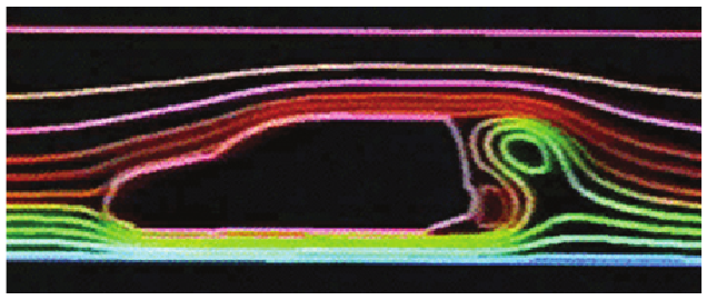
Figure 1. Airflow modeling in the 1980s, Hanna and Parry (2011).
It is characterized by an updated paradigm of using IOP modeling in the design process of an industrial product. Paradigm innovations have touched upon development processes, their focus on design based on simulation results, which increases the overall responsibility of the calculation engineers, and also makes the simulation results the only basis for making decisions that can then have serious financial consequences. This transfer of responsibility, in turn, affects producers of VGD software, who should not only improve existing physical models and increase solvers' performance, but also quickly respond to changing industrial requirements, new approaches to the introduction of VGD modeling into the product design process, new business models license purchases, innovative usability concepts.
')
Criteria such as ease of implementation, reliability, safety modeling and reproducibility become more important in industrial use of IOP, and over time will continue to crowd out the historically established criteria - accuracy of the result, increased productivity, which were essential for developers of IOP software. The excellent and stable quality of the simulation results obtained using the latest computing hardware, software and mathematical algorithms, is now regarded as a given. The new “third wave” in the development of commercial IoT software is fueled by the continuing increase in performance of computing and graphics hardware, which leads to a more favorable price-performance ratio. This development, in addition to the innovations in IoT technology and new requirements for user knowledge, characterizes the “third wave”.
This article analyzes the three phases of the development of commercial IoT software for design, described in a historical context, discusses possible areas for further development.
1. Three waves of commercial IoT
Currently, there are many publications on the flow modeling history. Earlier on this topic were the pioneers of the IOO as Brian Spalding, David Tetchell, Ferit Boysan, Michael Engelman. The collected set of historical facts, technical data and personal impressions of the authors give a detailed picture of the development of engineering modeling from scientific research to modern IOT of products that we know today, which are developed and supported on an industrial scale by multinational large companies. Due to the attachment to existing computing hardware, this development, in particular, at an early stage, was mainly due to research projects for the aerospace and defense industries, but later more and more interest was expressed on the part of civilian industry. Looking back, we can distinguish three main periods of IOP software development:
- The first wave: the beginning of commercial IoT software in the 70s and 80s.
- The second wave: in the 90s, the appearance of IOP in research and development departments of large industrial companies.
A good overview with an extensive biography is contained in the works of Hanna and Parry (2011). Interesting presentations were made by Runchal (2008) and Totchell (2009).
1.1 The First Wave: The Beginning of Commercial IoT Software
The first IoT codes are rooted in the work of the T-3 Computational Fluid Dynamics Group operating at the Los Alamos National Laboratory (USA) since 1958, and research projects led by Professor Spalding, Imperial College London, in the 1960s and 1970s.
In the late 1960s, Professor Spalding, founded the consulting company CHAM Ltd. (Concentracion, Heat and Momentum - the concentration of heat and moments), located in Imperial College London. The era of commercial VGD software began in 1974, when CHAM Ltd. moved to her own office in New Madeleine, a suburb of London. Initially, the development of VGD programs for the needs of the customer was the main activity of CHAM. Then it became too time consuming and inefficient, so CHAM decided to develop a general purpose IGP package for internal consulting work, then released it as a commercial product of PHOENICS in 1981. This fact can be viewed as the birth of the IoT software industry (see CHAM Ltd, 2008 ). Others quickly followed suit. Fluid Dynamics International (USA) in 1982 released the FIDAP, IOP package based on the finite element method (FEM), and Create Inc (USA), in 1983 released the IOP package based on the finite volume method (ICE) Fluent. In 1980, Dr. Hirt founded Flow Science (USA) as a branch of Los Alamos National Laboratory and in 1985 released Flow-3D. A number of subsequent IOP packages, including, for example, Flow3D from the UK Atomic Energy Administration (England) in 1987 and TASCflow, released by Applied Scientific Computing (Canada) - today both exist as part of ANSYS CFX. Computational Dynamics / ADAPCO (England / USA), co-founder Professor David Gosman, another professor at Imperial College London, released StarCD in 1989.
In the early 90s, workstation maker Silicon Graphics, listed in its software catalog, already 18 commercial IoT packages, which were compatible with their hardware products, covering about $ 30 million. IoT market (Boisan et al., 2009). The main technologies in these VGD packages were developed by former employees or freelance scientists of the two aforementioned research institutes - in London and Los Alamos, or based on their scientific publications. But there were other developers of VGD technology: in the 1980s, alternative approaches to VGD modeling emerged as part of the aviation and cosmonautics development program in the countries of the former Soviet Union, largely unnoticed by the Western scientific community due to the political situation. The technical tasks solved by them using VGD modeling were similar to those that existed in the West, but the available hardware and computing resources for solving them were much more limited. However, due to the high political priority of these research programs, extensive experimental data were obtained for many cases of fluid flow, heat transfer phenomena, especially flow phenomena in the near-wall area. This situation led to the emergence of alternative methods of IOP, which, based on well-known methods for Cartesian grids, published in the West, combined numerical, analytical and empirical data. Such an innovative approach made it possible to obtain high-quality simulation results with low requirements for computing resources, combined with the efficiency of methods using Cartesian meshes. In the course of the gradual economic liberalization of the Soviet Union, in the late 1980s, several teams of scientists commercialized this VGD technology and, starting in the 1990s, engaged in the sale of their products and services in Europe and Asia. The most famous products of this kind were Aerospace-3D by Professor Gavrilyuk and his team (Petrova, 1998 and Alyamovsky, 2008) and FlowVision by Dr. Aksenov and his team (Aksenov et al. 2003).
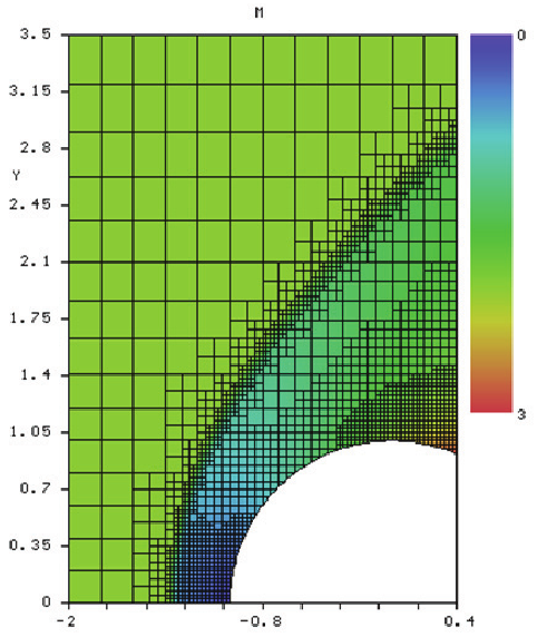
Figure 2. Simulation results in Aeroshape-3D (Parry et al., 2012)
Characteristic features of the first VGD software were: primitive by today's standards, the user interface for data entry, rudimentary graphics and very modest computing resources, in particular, the amount of available RAM memory, which was constantly lacking, which greatly limited the maximum size of the model. These restrictions led to very high user requirements for geometry modeling and physics, and the real task had to be analyzed, simplified and transferred to the program in a rather laborious way. Uncertainties present when choosing the configuration of the physical model and the risk of data entry errors were very high, and thus there was a need for a comprehensive assessment of the data obtained, and verification of the simulation results was the usual next step of the workflow. All this required extensive knowledge in the field of numerical methods, the fundamentals and limitations of physical models when used in the VGD model. Thus, the users of VGD technology at that time were exclusively scientists and early-trained engineers who could partially or fully compare the simulation results with experimental data. This period was also characterized by the fact that, due to limited experience with IOP applications and the high level of competition in the IAP software tools market, manufacturers, as a rule, strongly overestimated the suitability of their products for solving production problems. This, in combination with the questions of the first industrial consumers, regarding the quality of results achievable with IGD at a given cost, extremely slowly enhanced the IGD modeling reputation, so extremely expensive and with too vague in terms of suitability for use. This negative reputation persisted in most of the engineering community for more than two decades, but the situation changed during the third phase of IoT software development, when IoT modeling became the daily work for a new generation of users.
In the early 1990s, the conditions for VGD software and simulation changed fairly quickly. Computing equipment, mathematical methods and physical models - there was a huge increase in productivity in everything. CPU speed and RAM size increased rapidly and became cheaper, providing industrial users with new, more affordable hardware, such as UNIX and PC workstations, and a little later, with the advent of computing clusters, access to high-performance computing (HPC). These new features on the hardware side, of course, also contributed to the development on the software side. Numerical methods such as the unstructured Finite Volume Method, multigrid methods, dynamic grids, etc. suitable for complex geometries and optimized for HPC, have become commercially available, as well as more reliable, more flexible and more widely applicable for modeling physical processes. Thus, new areas of IOP use have emerged. The applicability of VGD technology has greatly increased and finally it became possible to use the real size of the models for existing industrial needs. Hanna and Parry (2011) analyzed this development and found a direct correlation between Moore's law for computational power and, for example, the size of a model for a race car during IOP modeling. These new opportunities heralded the advent of a new era in the use of commercial VGD software — its appearance in the scientific and design departments of industrial companies.

Figure 3. The development of IOP with respect to the growth of hardware capabilities - IG trends in the examples of Formula 1 racing cars 1990-2010 (Hanna and Parry, 2011)
1.2 The second wave: IOP appears in the research departments of industrial companies
Based on technologies typical of the first wave, Flometrics Ltd., founded in 1988 by David Tutchell and Harvey Rosten in Kingston-upon-Thames (England), played a leading role in the marketing of the VGD software developed directly for industrial needs by releasing the FloTHERM package in 1989. Both founders worked at CHAM Ltd in leadership positions before leaving and establishing Flometrics to “provide the industry with good science” (Tatchell, 2009). FloTHERM introduced the first changes in the paradigm of industrial IOT, the former emphasis on complex IOT technology shifted more towards solving engineering industrial problems, this became the main goal. It also meant that, from now on, engineers, and not just scientists, who were previously the only users of VGD software, are involved in product development. However, existing IOT technologies, computing hardware, and operating systems put some limitations on this innovative approach. Therefore, Flometrics initially focused only on two application areas: electronics cooling (FloTHERM) and interaction with the HVAC environment (FloVENT). The requirements for engineering-oriented IOP software for these areas at that time were already relatively clearly defined and, more importantly, were able to satisfy them.
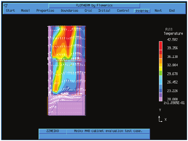
Figure 4. Early version of FloTHERM (Hanna and Parry, 2011)
This concept has opened up completely new market opportunities, because for the first time a much more extensive group of users with industrial problems and the experience of solving them was covered. It was also the moment when engineers were able to use VGD modeling as a tool for product design without specific knowledge of numerical methods and not having extensive experience working with IOT. The solution of the technical engineering problem was in the spotlight, while the underlying IoT technology faded into the background.
Obviously, the remaining IOP providers also recognized this paradigm shift and noted new business opportunities, responding to this trend with their suggestions. This was, for example, MixSim, released in 1996, which had a specific interface for modeling the mixing process and was based on the Fluent solver. Fluid Dynamics International has entered the IoT market for electronics cooling with its Icepak product based on the FIDAP solver, and CD Adapco presented various engineering tools for the automotive industry. New companies such as Exa Corporation (PowerFlow developers) and Blue Ridge Numerics (CFdesign developers) saw new opportunities and entered the IoT market with their own special tools for industrial applications. In general, investments from all IoT providers were observed to improve user interfaces, solver performance and improve the reliability of physical models in order to consolidate IoT in research and development and engineering departments of large industrial companies, thus attracting a new generation of IoT users.
This second wave of VGD software development for industrial applications ended in the early 1990s and mid-2000s. It was characterized by a combination of the availability of high-quality IOP modeling and the use of cheaper and more productive computational tools. This led to a sharp increase in demand for VGD modeling, especially from large companies, which prompted the manufacturers of VGD software to further democratize VGD technology. Nevertheless, many users have noticed another trend characterizing this period: the beginning of the consolidation of players in the VGD software industry through the acquisitions and withdrawals of some participants from the market. Many emerging VGD systems became obsolete and required large investments for further development. Most VGD software providers did not have enough planned steady revenue growth. The dramatic increase in development costs and stiffer competition forced companies to join forces to remain competitive and solve future problems. During this period, the foundations were laid for numerous acquisitions that led to the emergence of VGD companies with a staff of several thousand employees and who are currently dominant in the VGD software market.

Figure 5. FIDAP user interface in the late 1990s (University of Delaware, 2007)
After fixing the IOP as a successful tool for functional design, verification and optimization of product design, processes, product characteristics - in large industrial companies in the 2000s, the reputation of this technology among engineers has increased significantly. With hundreds of examples, it was proved that with the correct actions of the user in the process of modeling, the use of commercial VGD software can lead to saving time and costs for design. As a result, the demand for IOP increased strongly, especially in medium and small companies, which could now reduce the costs associated with the manufacture of prototypes, which they often had to order from third-party companies. However, the high cost of IOP modeling in relation to the cost of physical experiments in the early 2000s was still a serious obstacle. These costs were primarily related to personnel costs: to train or hire highly qualified users, a relatively long way from a user to a specialist, a tedious modeling process (especially if the geometry is complex), and the relatively high cost of software licenses. Another important aspect was the need to integrate VGD modeling into the product design process, since these companies most often did not have a special modeling department (for now). This meant that engineers from the design group or design should independently perform the modeling, and the effectiveness of the modeling projects should increase due to the fact that the IOP results will be available almost simultaneously with the product design cycles, which will allow to formulate proposals for improving the design.

Figure 6. Pyramid of IOP use (Hanna and Parry, 2011)
The processing of industrial level geometry played a key role. At that time, geometry data was already provided in the form of 3D CAD, which was then used with the least modifications and simplifications for subsequent automated grid generation. The VGD software market has responded to these requirements with a multitude of new, improved products and the third wave of VGD software for the design of industrial products started then continues to this day.
1.3. The third wave: IOP becomes an important element of the product design process
At the third stage, the main role is played by the main CAD and PLM manufacturers. Since the 1990s, they have successfully implemented the concept of Product Lifecycle Management PLM, which also includes CAE. As a result, consumers put pressure on commercial IoT vendors to conform to this concept and take measures to integrate their products into the main PLM systems. Thus, in the 2000s, almost all IoT vendors added at least new CAD import interfaces to their systems. Many have developed bidirectional links with major CAD / PLM systems, some have built their VGD technologies directly into 3D CAD systems.
Manufacturers of CAD systems have supported these innovations to provide a complete solution in the PLM system framework, providing support through external specialized developer modules. At this stage, products such as Fluetn for CATIA (Fluetn Inc), CFdesign (Blue Ridge Numerics) and FloWorks (NIKA GmbH) were combined. Also, to support these new requirements, new IOP technology has been developed. For example, since 1999, CD-Adapco has successfully used an innovative object-oriented approach in the development of STAR-CCM +. NIKA GmbH, founded in 1999 as a German-Russian joint venture, became a typical example of a supplier of a new commercial VGD software at the beginning of the third wave. NIKA was developed on the basis of the above-mentioned Aerospace-3D technology, VGD software with embedded CAD, which today is supplied as separate modules of the main 3D CAD system (Fig. 7).

Figure 7. FloEFD for Creo by Mentor Graphics
In response to these changing market conditions, Blue Ridge Numerics introduced the CFdesign package as an “Advance IoT” system. The PLM suppliers themselves also expanded (at the expense of the acquisition cost) their activities in the field of CAD-integrated VGD software to provide better support for the product design process. Representatives of this market segment are Dassault Systemes and their SIMULIA Abaqus / CFD, and Siemens PLSM with their NX Advanced Flow and Femap Flow Solvers. Autodesk has also strengthened its VGD software portfolio with the acquisition of Blue Ridge Numerics CFdesign in addition to their Algor suite.
The ongoing third wave provided newcomers from other areas with the opportunity to enter the IoT market, refreshing it with new advanced technologies. Such an example was XFlow from Next Limit Technologies (Spain), which brought to the engineering community not so much its alternative IoT technology, which originated from the film industry, as the new user interface is more similar to the animation software interface. Autodesk's Project Falcon also brought game elements to the IOT world.
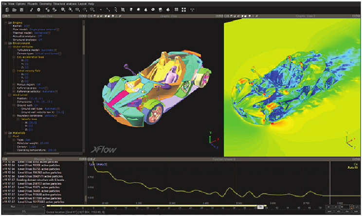
Figure 8. Next Limit Technologies XFlow user interface (MSC Software, 2011)
It seems that the following trend has emerged: the IAP software market is becoming increasingly diverse due to new, innovative, innovative approaches, especially in the area of user experience interaction (User Experience UX) and usability.But everyone had one thing in common: an industrial user, with his or her need for an easy-to-use, goal-oriented, automated, reliable, efficient and easily accessible VGD software, which would become an indispensable tool for creating an electronic prototype. This is caused by changes in the development processes and, as a result, a change in the role of the calculation engineer. Such aspects as the integration process, reliability, safety of modeling, reproducibility become major when deciding on the purchase of a particular IOT software. Further development of VGD software will also be based on these requirements and will lead to the emergence on the market of new exciting technologies and products. Thus in the near future we can expect the appearance of the fourth wave ...
2. What's Next - Vision
Hannah and Parry (2011) described their vision of the future as follows: “According to the authors, the“ Holy Grail ”of IoT looks like this: in real time, just press a button that is automated, easy to use, bidirectional, and IHT is multiphysical. Today, some IOP products are closer to these ideals, some further, but much more needs to be done to achieve this nirvana in the next 20 years, including from the hardware, algorithmic, physical modeling and industry advances. ”
Such a long-term goal, however, can only be achieved gradually. As the authors themselves note, there are still many problems to solve on the way. Perhaps this end goal will need to be updated periodically, because the environmental factors of the design process are also subject to change - IOT is an iterative process! The following section discusses some of the milestones on the path to the “Holy Grail”.
2.1 Multiphysics
An important aspect of the IGC's “Holy Grail” is a more realistic representation of complex physical reality, without the artificial “constraints” that exist today, formed as the history of IoT develops: computational structural mechanics, multibody dynamics, kinematics, etc. as separate disciplines using various numerical techniques. The first signs of this are already manifested in what has become widely known as multi-physical modeling. However, this often means slightly more than substituting the results of one simulation (for example, thermal analysis) as initial or boundary conditions for another model (for example, thermo-mechanical stress).
Some software vendors, such as ANSYS and COMSOL, have chosen multiphysics as the main aspect of their product philosophy and provide a wide range of modeling capabilities. However, today, the focus of multiphysical applications is the development of functions and the resolution of technical problems that arise when individual components work together due to their historical or technical differences, which may cause incompatibility. To help in solving this problem come frameworks that provide the necessary infrastructure for collaboration. These frameworks may be the result of the work of a supplier of a multi-physical application or provided by independent third-party developers as middleware. One such example is the Fraunhofer MpCCI Framework.

Figure 9. MpCCI Vizualizer from Fraunhofer SCAI (Fraunhofer SCAI, 2012)
Another limiting factor of today's multiphysical approaches is the correct representation of the actual physical situation for individual modules of the solver, which is necessary for this simulation project. In order to ensure that the results of one simulation can be used as input for the next, it is often necessary to have a white box style model that accepts the original geometry without any simplification and requires modeling all relevant physical effects with all the details, additional computing costs. Black box models, which can provide a significant increase in modeling efficiency, but are limited to only one aspect of the problem (for example, the thermal model of the electronic component), do not fit this paradigm.
Today, the choice of suitable modules, their configuration and location in the modeling workflow is the responsibility of the user, the actual workflow is determined by the combined requirements for the solver modules, and not by the physics of the specification. Therefore, the name of “multivalculation” is most likely more appropriate for this situation.
A prerequisite for the future success of this approach is not just communication, but rather the integration of individual solvers into a single, consistent solution methodology that allows the user to focus on physics (only possible in one section of physics) and get a modeling environment into which you can substitute any necessary numerical methods that will not contradict each other. This environment should be complemented by a design approach based on interaction experience (UX), which will shift the focus from “just undertaking the project” to “effectively solving the engineering problem posed” as a more important criterion.
2.2 Simulation methods
The idea of a solver of general physics seems possible for realization, but at the same time there is a problem of combining several very different, sometimes incompatible numerical methods. This variety of methods is, of course, useful, because the nature of the behavior of various physical factors of a product is very different and for each there is one or several suitable numerical methods that ensure good accuracy of the result and efficiency of the solution with low requirements for computing resources.
At the same time, it is undesirable to sacrifice this advantage and try to develop a single process for all possible physical tasks that will work in many areas, but much slower than each individual independent solution. Rather, the goal should be to develop the infrastructure of the solver, which will automatically use the best existing methods for each situation, combine and bi-directionally combine the results both within one model and in the case of several models. This means that very different methods must be integrated: sampling methods such as Finite Volume Method for internal flows; in combination with particle flux methods, such as the Hydrodynamics of Smoothed Particles for areas with several physical phases and a phase transition;one-dimensional methods for systems with large flows (hydrodynamics). Many elements for the implementation of this approach are already ready, and they are sufficiently developed and reliable. The task is to overcome the historically established dissociation of the solver modules in the direction of a single modeling engine, which will combine the best available methods, according to the simulated problem. The great advantage of this approach is that it will make it possible to completely exclude from the duties of an engineer a complete definition of a numerical workflow, giving it a workflow focused exclusively on the engineering problem and its solution. In this regard, we see how long the road is still to go to this “Holy Grail” of IoT.and sufficiently developed and reliable. The task is to overcome the historically established dissociation of the solver modules in the direction of a single modeling engine, which will combine the best available methods, according to the simulated problem. The great advantage of this approach is that it will make it possible to completely exclude from the duties of an engineer a complete definition of a numerical workflow, giving it a workflow focused exclusively on the engineering problem and its solution. In this regard, we see how long the road is still to go to this “Holy Grail” of IoT.and sufficiently developed and reliable. The task is to overcome the historically established dissociation of the solver modules in the direction of a single modeling engine, which will combine the best available methods, according to the simulated problem. The great advantage of this approach is that it will make it possible to completely exclude from the duties of an engineer a complete definition of a numerical workflow, giving it a workflow focused exclusively on the engineering problem and its solution. In this regard, we see how long the road is still to go to this “Holy Grail” of IoT.The great advantage of this approach is that it will make it possible to completely exclude from the duties of an engineer a complete definition of a numerical workflow, giving it a workflow focused exclusively on the engineering problem and its solution. In this regard, we see how long the road is still to go to this “Holy Grail” of IoT.The great advantage of this approach is that it will make it possible to completely exclude from the duties of an engineer a complete definition of a numerical workflow, giving it a workflow focused exclusively on the engineering problem and its solution. In this regard, we see how long the road is still to go to this “Holy Grail” of IoT.
2.3. (UX)
Undoubtedly, the future development of modeling software will be based on the needs of the engineer as the main user. This software will constantly adapt to the user's working environment, his needs and his individual intellectual capabilities, and not vice versa. This will affect both the overall concept and each individual piece of software. The same applies to the product description process and the implementation by the software vendor. Already today, many software companies have introduced modern development processes, such as Agile. This provides a natural process of applying user-friendly design principles, which is also a prerequisite for effectively implementing usability requirements with the overall goal of creating and maintaining a high level of interaction experience (UX).Development in this direction will undoubtedly lead to the emergence of new attractive products on the market for IAP software.
The working environment of engineers and designers will also continue to change. There are new input methods that better reflect the natural movements of a person. This includes, for example, the appearance of touch screens and elements of augmented reality. In the same way, new visualization methods will appear for a more ergonomic and accurate presentation of the simulation of the physical situation. It has been less than 100 years from engineers, technologists and workers using printed two-dimensional drawings to printing three-dimensional models on a 3D printer. This development will continue and the engineer will continue to play a major role in the decision-making process in the design process in the foreseeable future. This trend, caused and actively supported by modeling software, will become increasingly important.Visualization and transfer of simulation results with ever-increasing reliance on virtual prototyping for the development of cost-effective products is closely related to the increased responsibility of the calculation engineer for the conclusions made by him.

Figure 10. Levels of Agile methodology - user-driven development (Limina Application Office, 2012)
However, changes will occur not only at the abstract, but also at the conceptual level - so the experience of interaction (UX) and usability will play a much more important role as a decision criterion when choosing a tool. Every detail of the user interface requires special attention. Many interfaces of today's VGD software will remain at the level of the first emerging VGD interfaces, even if they are replaced with visually attractive surfaces. The problem is not so much in appearance as the stuffing of this software and its behavior. Since 1990, Jakob Nielsen has developed what has become a rather popular list of common user interface design principles - “10 usability heuristics” (Nielsen et al., 1993). Next, we tried to briefly comment on the application of these rules in context to the future modeling software,both from the practical and theoretical sides:
Displaying the state of the system: the system should always inform users about what is happening at the moment through the appropriate feedback bodies within a reasonable time.
- Concept: real-time modeling is the ultimate goal, so this is a very important aspect of the IG's “Holy Grail”.
- Practice: especially during long-term actions, such as working a solver, checking geometry, transferring data, displaying information about the current state is necessary. This aspect becomes especially important when actions are performed remotely. The current trend of cloud computing will require an increasing need for compliance with this rule.
Correspondence between the system and the real world: The system should speak in the user's language, words, phrases and terms that are understandable to the user, and not terms defined by the system itself. According to this rule, information should appear in a natural and logical order.
- Concept: This rule applies directly to complex workflows, such as incorporation of several physical processes into a single model. As already noted, the software must match the workflow, the working context and capabilities of the user, and not vice versa.
- Practice: Many IGU user interfaces still use terminology familiar only to IG experts. The emphasis should be on terms from a specific engineering field, and this applies not only to the user interface, but also to all documentation, reference documentation and training materials.

Figure 11. The cover of Usability Engineering by Jacob Nielsen (Nielsen, 1993)
Restrictions and user freedom: People often make mistakes when choosing system functions and need an “emergency exit” to leave an undesirable state without having to go through a long dialogue. There should be support for undo / redo operations.
- Concept: The emergence of cloud computing introduces some difficulties - an emergency exit may not be fast enough, costly in resources, or not reliable enough due to user restrictions. Developers will need to constantly pay attention to this.
- Practice: Undo / redo operations have been indispensable in office applications for decades, but most of the current VGD software still doesn’t meet such basic usability requirements.
Consistency and standards: Users should not have situations where different words, situations or actions mean the same thing. Follow the rules of the platform.
- : , . , . .
- : . , / , , .. /.
Error warning: Improving error messages is an important job that prevents the reoccurrence of any problem that has already happened once. It is necessary either to eliminate the conditions for the occurrence of an error, or to enter additional confirmations from the user when trying to perform an action.
- : , - , .. . (UX), , , , , .
- : — , . /.
Recognition instead of additional questions: Minimize user memory by displaying used objects, actions, and options. The user does not have to memorize information from one part of the dialogue, while being in another. Instructions for using the system should be displayed or readily available when needed.
- Concept: The key to the conceptual design of a good user interface lies in the understanding of the user, his work environment and his workflows, the development of the use of software based on this research should occur with an emphasis on the user's natural sensations.
- Practice: Modern interactive user interface concepts are already based on this principle. But many details can still be improved - for example, lists of recent files, status information, a master assistant, etc.
Flexibility and efficiency of use: Accelerators - imperceptible to the novice user - can often speed up the work of an experienced user, thus the system satisfies the requirements of both inexperienced and experienced users. Provide users with the ability to adapt frequently performed actions.
- Concept: Again, this leads to the requirement that the software must match the workflow, the work environment and the user's individual capabilities, and not vice versa. The software should help the user build on experience and adapt to this growth.
- Practice: Windows already has the concept of hot keys, with which many users are well acquainted, so it’s better to use this concept. Touch interfaces have the concept of gestures, which should also be used, even if only a mouse is available. The ability to create your own scripts will help experienced users set up their own automation features at relatively low costs.
Aesthetic and minimalistic design: Dialogues should not contain unnecessary or rarely used information. Each new information block in the dialogue competes with the already existing ones and reduces their relative visibility.
- Concept: Usability quality is not measured by the number of user interface buttons. The software with a good design recognizes the next steps of the user and offers him exactly those functions that may be related to the next step.
- Practice: For multi-functional products, such as IOP software, most often less is better. It is enough to display the available functions, and gray paint over inaccessible. Access to context-sensitive functions related to the active object will be automatically granted.
Help users find, recognize and correct errors: Error messages should be expressed in simple language (without codes), accurately describe the problem, constructively suggest a solution.
- : , “ ”, . , (UX), .
- : , , — , , .
Help and documentation: Although it is best if the system can be used completely without documentation, it may be necessary to have help and documentation. Any kind of information of this kind should be easy to find, with an emphasis on the user's tasks, the materials should contain lists of steps for obtaining a particular result, but not too long.
- Concept: Help is not limited to textual or graphic explanations; It should use all available media, including short videos, Internet resources, links to online user communities and technical support, etc.
- Practice: It is better to see once than hear a hundred times: this principle applies in particular to engineers, as the main users of IOP.
3. Conclusion
Commercial VGD software for industrial applications for over 30 years. Three decades of successful IOP modeling by hundreds of thousands of scientists, engineers, and students have made this technology an indispensable tool that is embedded in the design process in many industries today. While the classical technology of IOP is largely matured, new exciting concepts and technologies for solving IOP of the future are rapidly developing. After two main waves of commercial IOP development, each of which had its own changes in the paradigm, we are currently experiencing a third wave, in which the paradigm shifts towards the introduction of IOT software in the design process. Then, of course, the fourth wave of IOP software will appear. The authors believe that this will be a new step on the way to the “Holy Grail” of IoT: in real time,“Just press the button”, an automated, easy-to-use, bidirectional, multi-physical support ... and the classic IOP of the second wave will be left far behind.
Source: https://habr.com/ru/post/367463/
All Articles