Black Swift: Using EJTAG
My previous publication of EJTAG: although the hacker’s attraction was warmly received by the public, it had some flaws: for example, the performance of the EJTAG transmission was demonstrated too low (as much as 2 KB / s!).
Unfortunately, I managed to bring the JTAG interface of the MR3020 board to total disrepair (the TDI wire was torn off along with a piece of SMD resistor R16). Since it was not possible to fix the damage, the defects remained uncorrected.
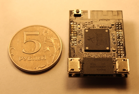
A few days ago I received a Black Swift Pro board with an adapter from Black Swift project manager Dmitry Zherebkov. The Black Swift Pro is similar in many respects to the MR3020, which means that I had the opportunity to write a publication about EJTAG on Black Swift and eliminate past shortcomings!
Warning: the following is a description of how to work with EJTAG for the Black Swift board using free software; It is assumed that the reader does not fall into a stupor from the command line interface, knows who the AR9331, MR3020 and EJTAG are, know where to get the cross-compiler for MIPS and guess why they use minicom. If you have any questions about the use of EJTAG on the Black Swift board, the author recommends that you first look for the answer in the EJTAG publication : attraction for hackers .
Black Swift: Unlike TP-Link MR3020
Unlike the TP-Link MR3020, Black Swift is not a complete product designed to solve a fixed problem.
Just the opposite: the Black Swift board is designed so that users can easily create their own products on its base. For this reason, the Black Swift board has much fewer restrictions (both software and hardware) for conducting experiments.
The dimensions of Black Swift are quite small, the board uses connectors, which by their nature are similar to connectors on Arduino-like boards, but having twice the distance between adjacent connectors is 1.27 mm. Because of this miniature, in order to simplify prototyping with such a board, it is proposed to use a special adapter that allows you to use the usual “big” wires from the Arduino:
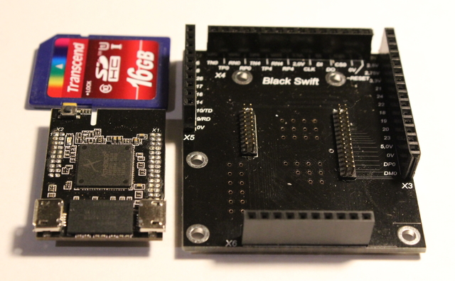
The SD card in the photo is for scale only.
The Black Swift ROM is flashed with a u-boot_mod base boot loader for this board.
At startup, the loader displays the following message in the UART (UART settings: 115200 8n1):
 **********************************************
 * U-Boot 1.1.4 (Apr 1 2015) *
 **********************************************

 U-Boot for Black Swift board (AR9331)

 DRAM: 64 MB DDR2 16-bit
 FLASH: Winbond W25Q128 (16 MB)
 CLOCKS: 400/400/200/33 MHz (CPU / RAM / AHB / SPI)
If within 1 second the user does not send any symbol to the UART, then the OS is loaded based on OpenWrt. If the user has time to send a character to the loader, then the loader command line becomes available. From this line it is possible to give the command to load data into RAM (via UART via Y-Modem or via Ethernet via tftp) and transfer control to any address; there are even commands for reprogramming the ROM.
')
At first glance, Black Swift for the developer of embedded software has a lot of advantages over the MR3020:
- connecting to almost any AR9331 interface (including JTAG) has become much easier;
- the loader is quite friendly (in the MR3020, the possibilities for loading user codes into RAM were severely limited);
- if you don’t touch anything, the GPIO11 / JS AR9331 input on the Black Swift is connected to the VDD25, which corresponds to the permission to use the EJTAG (recall that on the MR3020 you had to specifically press the SW1 button);
- In the Black Swift Pro version, it became possible to connect a boot ROM to the programmer (see below for AR9331 features).
But, as they say, believe me, everything is not so simple here ...
Nothing foreshadowed trouble
It turned out that the firmware on the basis of u-boot_mod, although it allows you to load the code into RAM and execute it, but, like the firmware MR3020, it is hostile to EJTAG lovers and tries to disable EJTAG programmatically shortly after the start.
Using the MR3020 experience associated with disabling the SPI Flash boot ROM due to the breaking of the CS circuit is rather difficult.
in spite of the fact that there are microswitches on the Black Swift Pro , which ensure disconnection of the boot ROM from the AR9331 (which, according to the authors, allows the use of an external programmer). Access to these microswitches on the board installed on the standard adapter, to put it mildly, is difficult. In order to accurately switch the switches to the desired position, the board will have to be removed from the adapter. There are no microswitches on the Black Swift board (not Pro!). It is theoretically possible to solder a pair of wires to a microswitch or a ROM chip for closing / opening the CS circuit from the outside, but such a refinement requires the ability to solder well (I think the photo below gives an idea of the complexity of the modification).

Why do you need micro switches on Black Swift Pro?
The fact is that without a detach from the AR9331, attempts to reprogram (or even just read) the SPI Flash boot ROM chip are doomed to failure - the AR9331 persistently drives the SPI line even with an active RESET line. On Black Swift Pro, four microswitches allow you to solve this problem by completely disconnecting the boot ROM from the AR9331, which allows you to successfully use an external programmer.
Thus, it will be difficult to use the JTAG revitalization technique, which works successfully on the MR3020.
We will go another way.
“A dirty hack will allow JTAG poyuzat”
So the problem is that the u-boot_mod loader disables JTAG.
Let's see what u-boot_mod does when it starts (let me remind you that after removing the signal, any processor with MIPS architecture starts to
0xbfc00000 instructions from address 0xbfc00000 ): bfc00000: 100000ff b 0xbfc00400
bfc00004: 00000000 nop If you replace the branch command with the address
0xbfc00400 with the branch command with the address 0xbfc00000 , like this: bfc00000: 1000ffff b 0xbfc00000
bfc00004: 00000000 nop then u-boot_mod will not be able to do its dirty deed to disable JTAG.
Of course, the proposed solution is very clumsy ...
and it would be much better to fix the firmware in such a way that access to JTAG always remained (or at least under a certain condition), but, unfortunately, at the time of preparing this publication, the source code of the firmware was not available (see the forum black-swift.ru ) , and absolutely no one wants to make non-trivial corrections to the binary firmware.
Replacement can be done using an external programmer, but in order not to make unnecessary movements, it is better to use barebox.
A warning! The actions described below may result in a complete flirting of your Black Swift card.
Build barebox
To modify the u-boot_mod bootloader already flashed in the boot ROM, we use barebox from the official git repository barebox.org. Download the source code from the next branch:
$ git clone -b next git: //git.pengutronix.de/git/barebox.git
Why is it necessary to download the next branch from the git repository?
We drag the next branch for the only trivial change that will teach barebox to work with the ROM chip installed in Black Swift:
At the time of publication, this change has not yet fallen into a stable version of barebox.
 commit bd3e5011346e3d4d03ac076ada5768c2cf197dc4
 Author: Antony Pavlov <antonynpavlov@gmail.com>
 Date: Mon Apr 13 23:56:41 2015 +0300

     mtd: m25p80: import ID for Winbond W25Q128FVSSI from linux

     Winbond W25Q128FVSSI chip is used in the Black Swift board,
     (see http://www.black-swift.com for details).
At the time of publication, this change has not yet fallen into a stable version of barebox.
Go to the directory with the source code, make the configuration and build:
  $ cd barebox
  barebox $ export ARCH = mips
  barebox $ export CROSS_COMPILE = / opt / mips-2014.11 / bin / mips-linux-gnu-
  barebox $ make tplink-mr3020_defconfig
  barebox $ sed "s / # CONFIG_PARTITION is not set / CONFIG_PARTITION = y /" -i .config
  barebox $ sed "s / # CONFIG_CMD_PARTITION is not set / CONFIG_CMD_PARTITION = y /" -i .config
  barebox $ make
If the build was successful, we get the file
barebox.bin .It remains to download this file in the Black Swift RAM and start.
Connecting a FT2232H layout to Black Swift
To connect to the UART and JTAG interfaces of the AR9331 chip, we will use the FT2232H breadboard (see also FT2232 breakout board ).
Although the Black Swift Pro board has its own USB-UART converter, it is more convenient to use the FT2232H layout tool for connecting the UART for several reasons:
- in this case, only one USB cable is used for the connection;
- energizing the Black Swift from the breadboard (although its load capacity is limited) and wanting to disconnect the power from the Black Swift for a while, we disconnect the power line from the breadboard; so we are free from the problem with the renumbering of USB serial ports (ttyUSBxx) in linux, which can arise if we temporarily disable Black Swift Pro;
- decreases the likelihood of damaging the Black Swift by inserting / removing the microUSB connector;
- using a layout you don’t have to think about which Black Swift option you are working with (Pro or not Pro) (you still need a layout to connect via JTAG).
Here is the connection diagram:

Appearance of the Black Swift FT2232H:

Modification of u-boot_mod
After the layout of the FT2232H is connected to Black Swift, you can proceed with the modification of u-boot_mod. To do this, run minicom.
Next, we restart Black Swift (this can be done either by temporarily cutting off the power from the board, or by closing the RESET input to ground (0V)).
As soon as we notice a message in minicom
Hit any key to stop autobooting
you need to interrupt the download by pressing any key in minicom, after which the
BSB> boot loader should appear.Now we load
barebox.bin into RAM using the Y-Modem protocol (to use Y-Modem on Debian, in addition to minicom, the lrzsz package must be installed).To do this, in the bootloader command line, start data reception via Y-Modem:
BSB> loady 0xa0200000
In minicom'e start sending. If minicom is configured as in the EJTAG publication : attraction for hackers, to send a file, you need to press Ctrl-B S, select ymodem in the menu, and then either select the file using the menu, or press Enter and enter the path to the
barebox.bin file manually .After the successful completion of the download, it remains only to transfer control to the download address
barebox.bin :BSB> go 0xa0200000 ## Starting application at 0xA0200000 ... barebox 2015.04.0-00103-g8397d68 # 1 Fri Apr 17 08:59:12 MSK 2015 Board: TP-LINK MR3020 m25p80 m25p80 @ 00: w25q128 (16384 Kbytes) malloc space: 0xa0400000 -> 0xa07fffff (size 4 MiB) environment load / dev / env0: No such file or directory Maybe you have to create the partition. running / env / bin / init ... / env / bin / init not found barebox: /
Line
m25p80 m25p80 @ 00: w25q128 (16384 Kbytes)
from the output above and tells us that barebox found the boot rom w25q128.
To access the boot rom, barebox creates a device / dev / spiflash. In order to work with the ROM was more convenient, as well as to reduce the likelihood of an error, we divide the ROM into sections. To do this, refer to the description of the structure of flash memory.
Use the addpart command to highlight sections:
 barebox: / addpart / dev / spiflash 128K @ 0 (u-boot)
 barebox: / addpart / dev / spiflash 64K @ 128K (u-boot-env)
 barebox: / addpart / dev / spiflash 16128K @ 192K (open-wrt)
 barebox: / addpart / dev / spiflash 64K @ 16320K (art)
Although we are only interested in the section with u-boot, out of pure curiosity we will check what is in the first 64 bytes of each section:
 barebox: / md -s /dev/spiflash.u-boot 0 + 64
 00000000: 100000ff 00000000 100000fd 00000000 ................
 00000010: 1000018e 00000000 1000018c 00000000 ................
 00000020: 1000018a 00000000 10000188 00000000 ................
 00000030: 10000186 00000000 10000184 00000000 ................

 barebox: / md -s /dev/spiflash.u-boot-env 0 + 64
 00000000: 071043c4 626f6f74 636d643d 626f6f74 ..C.bootcmd = boot
 00000010: 6d203078 39463033 30303030 00626f6f m 0x9F030000.boo
 00000020: 7464656c 61793d31 00626175 64726174 tdelay = 1.baudrat
 00000030: 653d3131 35323030 00697061 6464723d e = 115200.ipaddr =

 barebox: / md - s /dev/spiflash.open-wrt 0 + 64
 00000000: 27051956 acb82611 551bcb1f 001503ef '..V .... U .......
 00000010: 80060000 80060000 bc6b30a9 05050203 ......... k0 .....
 00000020: 4d495053 204f7065 6e577274 204c696e MIPS OpenWrt Lin
 00000030: 75782d33 2e31302e 34390000 00000000 ux-3.10.49 ......

 barebox: / md -s /dev/spiflash.art 0 + 64
 00000000: 807b8591 2010ffff ffffffff ffffffff. {.. ...........
 00000010: ffffffff ffffffff ffffffff ffffffff ................
 00000020: ffffffff ffffffff ffffffff ffffffff ................
 00000030: ffffffff ffffffff ffffffff ffffffff ................
This small check shows that there are no errors in defining partition offsets - the beginning of u-boot_mod sits in spiflash.u-boot, the variables u-boot_mod are in spiflash.u-boot-env, and the image header in spiflash.open-wrt Linux openwrt.
The art section stores the base MAC address of the card, which is used to assign MAC addresses to all three network interfaces (one WiFi and two Ethernet).
Here, for example, what linux reports about the MAC addresses of the same board
 root @ BlackSwift: / dev # ifconfig -a |  grep HWaddr
 br-lan Link encap: Ethernet HWaddr 80: 7B: 85: 91: 20: 12
 eth0 Link encap: Ethernet HWaddr 80: 7B: 85: 91: 20: 11
 eth1 Link encap: Ethernet HWaddr 80: 7B: 85: 91: 20: 12
 wlan0 Link encap: Ethernet HWaddr 80: 7B: 85: 91: 20: 10
Now read the u-boot_mod image from ROM to RAM:
barebox: / memcpy -s /dev/spiflash.u-boot 0 0xa0100000
In barebox, this bit-bang read operation takes 49 seconds.
And how about reading from ROM in linux?
in linux main firmware with flash access, everything is much better (read performance over 2 MB / s):
 root @ BlackSwift: / dev # time dd if = mtdblock2 of = / tmp / test bs = 1M
 15 + 1 records in
 15 + 1 records out
 real 0m 7.07s
 user 0m 0.00s
 sys 0m 0.48s
Modify the u-boot_mod image in RAM and write it back to the ROM.
 barebox: / mw 0xa0100000 0x1000ffff
 barebox: / erase /dev/spiflash.u-boot
 barebox: / memcpy -d /dev/spiflash.u-boot 0xa0100000 0 0x20000
Updated ROM content:
 barebox: / md -s /dev/spiflash.u-boot 0 + 64
 00000000: 1000ffff 00000000 100000fd 00000000 ................
 00000010: 1000018e 00000000 1000018c 00000000 ................
 00000020: 1000018a 00000000 10000188 00000000 ................
 00000030: 10000186 00000000 10000184 00000000 ................
Attention, check carefully the contents of
/dev/spiflash.u-boot again before it's too late!Now Black Swift can be restarted. From barebox, restarting can be accomplished using the reset command:
barebox: / reset
Now the board can not work independently, but it becomes possible to use EJTAG. If necessary, using EJTAG, the board is easy to reset.
Using EJTAG
Unfortunately, stupidly using openocd scripts for the MR3020 for Black Swift will not work: the MR3020 uses the DDR1 memory chip while the Black Swift uses the DDR2 chip, which means another RAM controller initialization procedure is used.
I note the problems of publishing EJTAG: an attraction for hackers in the openocd part:
- according to Pavel Ferzer ( and he knows a lot about openocd! ), the publication promoted the vicious practice of working with openocd;
- too low transmission performance on the EJTAG was demonstrated (as much as 2 KB / s!).
This time I will try to avoid old mistakes. As part of openocd, there is already a configuration file for the TIAO USB Multi-Protocol Adapter (TUMPA) , which can be used for the FT2232 Board, so instead of a complete description, we simply import the configuration file for TUMPA (
interface/ftdi/tumpa.cfg ).To describe the connection of JTAG to AR9331 chip by Alexey Rempel, the configuration file
atheros_ar9331.cfg has already been created, so it can also be imported. Unfortunately, this file has been added to the openocd repository quite recently (see this commit ) and is not part of the openocd package for Debian.We'll have to download it separately:
$ wget -O atheros_ar9331.cfg "http://openocd.zylin.com/gitweb?p=openocd.git;a=blob_plain;f=tcl/target/atheros_ar9331.cfg;hb=7e66b02ba4f1453ab1c45eaebbee6e6eh6e6ef6ehg6e6bg6e5e6bg6bfxehd6bfxcfgbhg7gfgcfg.htfbcfgfgfgfgfgfgfgfgfgfgfgfgfgbhg7gfgbg7bfb6bf6bf6bf6bf6bf6bfbhb7bfb6bg6bfb6bf6cfgbhg7pfgfgtgtgtgcfgfgfc
In accordance with the openocd tradition, in the separate file named
black-swift.cfg will save the description of the board. This description uses atheros_ar9331.cfg and contains the DDR2 initialization procedure (the file was created based on tcl / board / tp-link_tl-mr3020.cfg ): source [find atheros_ar9331.cfg]
# ar9331_25mhz_pll_init is imported from tcl / board / tp-link_tl-mr3020.cfg
proc ar9331_25mhz_pll_init {} {
mww 0xb8050008 0x00018004; # bypass PLL; AHB_POST_DIV - ratio 4
mww 0xb8050004 0x00000352; # 34000 (ns) / 40ns (25MHz) = 0x352 (850)
mww 0xb8050000 0x40818000; # Power down control for CPU PLL
; # OUTDIV | REFDIV | Div_int
mww 0xb8050010 0x001003e8; # CPU PLL Dither FRAC Register
; # (disabled?)
mww 0xb8050000 0x00818000; # Power on | OUTDIV | REFDIV | Div_int
mww 0xb8050008 0x00008000; # remove bypass;
; # AHB_POST_DIV - ratio 2
}
proc ar9331_ddr2_init {} {
mww 0xb8000000 0x7fbc8cd0; # DDR_CONFIG - lots of DRAM confs
mww 0xb8000004 0x9dd0e6a8; # DDR_CONFIG2 - more DRAM confs
mww 0xb800008c 0x00000a59
mww 0xb8000010 0x00000008
mww 0xb8000090 0x00000000
mww 0xb8000010 0x00000010
mww 0xb8000094 0x00000000
mww 0xb8000010 0x00000020
mww 0xb800000c 0x00000000
mww 0xb8000010 0x00000002
mww 0xb8000008 0x00000100
mww 0xb8000010 0x00000001
mww 0xb8000010 0x00000008
mww 0xb8000010 0x00000004
mww 0xb8000010 0x00000004
mww 0xb8000008 0x00000a33
mww 0xb8000010 0x00000001
mww 0xb800000c 0x00000382
mww 0xb8000010 0x00000002
mww 0xb800000c 0x00000402
mww 0xb8000010 0x00000002
mww 0xb8000014 0x00004186
mww 0xb800001c 0x00000008
mww 0xb8000020 0x00000009
mww 0xb8000018 0x000000ff
}
$ TARGETNAME configure -event reset-init {
ar9331_25mhz_pll_init
sleep 1
ar9331_ddr2_init
}
set ram_boot_address 0xa0000000
$ TARGETNAME configure-work-area-phys 0xa1ffe000-work-area-size 0x1000 The reader may have a question ...
How was the sequence of records in the registers obtained, which ensured the initialization of the DDR2 memory controller? Such a sequence is obtained with the help of EJTAG! It is enough to trace the execution of u-boot_mod: the memory controller is initialized at the earliest stage, choosing the write instructions (store) from the trace, we get the desired sequence.
The configuration file
run-barebox.cfg , which puts everything together and provides for loading and running barebox.bin looks like this:source [find interface / ftdi / tumpa.cfg] adapter_khz 6000 source [find black-swift.cfg] init halt reset init load_image barebox / barebox.bin 0xa0100000 bin # General Purpose I / O Function (GPIO_FUNCTION_1) # # SPI_EN (18) enables SPI SPA Interface signals # in GPIO_2, GPIO_3, GPIO_4 and GPIO_5. # Res (15) reserved. This bit must be written with 1. # UART_EN (2) enables UART I / O on GPIO_9 (SIN) and GPIO_10 (SOUT). # mww 0xb8040028 0x48002 resume 0xa0100000 shutdown
So, after we have
atheros_ar9331.cfg , black-swift.cfg , run-barebox.cfg files in our working directory, we can download and run barebox: $ sudo openocd -f run-barebox.cfg
Open On-Chip Debugger 0.8.0 (2014-10-20-21: 48)
Licensed under GNU GPL v2
For bug reports, read
http://openocd.sourceforge.net/doc/doxygen/bugs.html
Info: only one transport option; autoselect 'jtag'
none separate
adapter speed: 6000 kHz
Error: no device found
Error: unable to open ftdi device with vid 0403, pid 8a98, description '*' and serial '*'
Info: clock speed 6000 kHz
Info: JTAG tap: ar9331.cpu tap / device found: 0x00000001 (mfg: 0x000, part: 0x0000, ver: 0x0)
target state: halted
target halted in MIPS32 mode due to debug-request, pc: 0xa080078c
189216 bytes written at address 0xa0100000
downloaded 189216 bytes in 0.459115s (402.473 KiB / s)
shutdown command invoked After the openocd finishes working in the minicom window, we can observe messages about the start of the barebox.
Note: in my particular case, it is not possible to raise the frequency of the JTAG clock signal above 6 MHz, since there is a deterioration in the transmitted data.
How to return to the original firmware?
For a one-time launch of the original firmware, the following
run-u-boot_mod.cfg script is run-u-boot_mod.cfg :source [find interface / ftdi / tumpa.cfg] adapter_khz 6000 source [find black-swift.cfg] init halt resume 0xbfc00400 shutdown
Note: therun-u-boot_mod.cfgwill not work immediately after powering up the board, since u-boot_mod to deal with mysterious errors AR9331 performs an additional reset. In order for the script to work, you must give a reset signal before launching it on the board. Another option: run the scriptrun-u-boot_mod.cfgtwice.
To permanently restore the original firmware, it is enough to follow the procedure described above for modifying the first branch instruction of the u-boot_mod bootloader with the only difference that instead of replacing
0x100000ff with 0x1000ffff , you need to replace 0x1000ffff back with 0x100000ff .Results
As demonstrated above, working on an EJTAG with Black Swift is quite possible. The 400 KB / s bandwidth allows you to comfortably load not only the barebox, but also the linux kernel; this is all the more relevant because when using a standard unpretentious adapter, the Ethernet interface is not derived.
Thanks
The author is grateful to the people, without whose participation this publication would hardly have been possible:
- Pavel Fertser for valuable comments and suggestions;
- Alexey Rempel for adding support for the TP-Link MR3020 board in openocd ;
- Dmitry Zherebkov for Black Swift Pro.
Source: https://habr.com/ru/post/366849/
All Articles