I and the diode, or the new adventures of the mouse
As you may remember, not so long ago I soldered a capacitor to my mouse and happily reported on this epoch-making event . But it soon became clear that my joy was premature. So, I bring to your attention the continuation of a detective story.
No, the button did not crumble to dust, as one of the commentators prophesied. And in general, none of those present guessed the fate of the long-suffering mouse, although, as I understand now, it was almost obvious.
')
On a tip from a respected ploop, I discovered the program xev , which among other things shows which buttons are pressed. I click the right button and see:
That is, whenever I press the right button (3), the mouse thinks that the left button (1) is also pressed! At this point, I remembered that after reworking this mouse, it became impossible to bring up the context menu in the Chrome window header. Then I did not attach any importance to this, because at about the same time, moving back and forth with the “back and forth” buttons also fell off, and only on Habré / GT and only on the second mouse, which I (my mother swear) did nothing with.
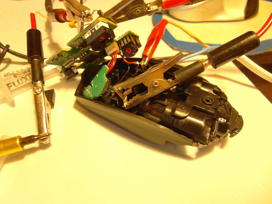
Vypayav capacitor, I was convinced - indeed, it was he who was guilty of pressing the extra button. And this put an end to the whole idea of a panacea for bounce from the previous post. Since there was no wish to choose between habrassucicide and a deal with conscience, I had to think how to overcome this most unpleasant side effect. So again we disassemble the mouse, cut in the oscilloscope and try to achieve the very understanding that we lacked last time.
The mouse appeared to be based on the nRF24LE1 microcontroller well-known in the nation.
By dialing, it was found that all the breaker leads go straight to the feet of the processor, and each such leg is connected to more than one switch. More specifically, the scheme appears as follows:
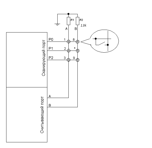
(An asterisk button means a dpi change button that does not pass to the mouse exit.)
This makes it possible to suspect the authors in the application of the technique called “matrix keyboard” . The scanning signal is alternately transmitted to the legs and looks at which reading legs it appeared. This allows you to save legs - because the buttons in this way can be set in proportion to the square of the number of used legs. (In this case, we have 6 buttons and 5 conclusions - that is, the whole one leg is saved. However, I forgot to ring the wheel, so it is possible that the same circuit serves the wheel, then it means saving two legs.)
But for now this is only an assumption, you need to check it.Let's set crocodiles on. Connect the P0 and A conductors (in terms of the previous picture) to the oscilloscope. By pressing the left button (1) we see:

At P0, a pulse with a duration of 20 microseconds (indicated by an arrow) is applied, which comes to the leg A at a closed switch. It is not visible here, but the interval between pulses is about 10-15 milliseconds. So, software bounce protection is still present, and it becomes unclear how it turns out that it does not help. But back to our sheep and release the button:

As we expected, the scanning signal on the reading foot disappears. And now press the left and right buttons at the same time:

And again, in full accordance with expectations, we get two signals from the two legs at the output, separated in time. If you now press the middle button, there will be three signals that will merge into one big line.
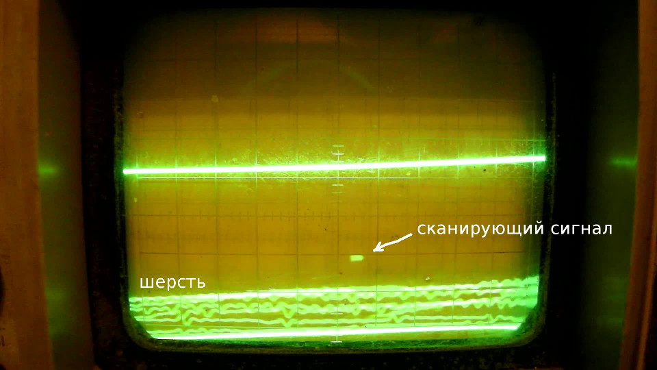
But how is it that when two buttons are pressed, the scanning legs do not short out with each other and do not spoil the signal to each other? In the above article for this proposed to use diodes. Here everything is simpler - when the leg is inactive, it is transferred to the Hi-Z (high resistance) mode, that is, it is actually disconnected from the circuit, and no current flows through it. As evidence in favor of this - if, with the buttons open, inadvertently touch the scanning port, the oscilloscope will show the characteristic “wool” (that is, interference from the radio broadcast received by our body):
To finally confirm our guess, we set up an experiment. If the button presses are registered by increasing the voltage, then if you close the scanning port to power, the mouse should perceive this as pressing all the buttons on this port.
Again, everything is as we expected, plus there were “Easter” buttons 6 and 7, which are not physically on the mouse (the wheel corresponds to buttons 4 and 5).
So, we know the truth about the mouse and its buttons. But how will this help us cope with our initial misfortune? To do this, we need to understand two more things - why the capacitor delays releasing the button and why it contributes to pressing it when another button is pressed.

When we close button 1, the capacitor instantly discharges, and the voltage on it becomes zero. As long as the button is pressed, the capacitor is shorted, so that the mouse perceives pressing the button as if there was no condenser.
Now let go of the button. Since the capacitor has a capacitance, the voltage on it is still zero. So, if we apply a scanning voltage (2.5 V power supply) to P0, then the input A will also have 2.5 volts, which corresponds to the pressed button.
However, with each such pulse, the capacitor will gradually be charged (through the resistance R1). And at one point, it will charge, say, up to 2 volts, and at the input A there will already be 0.5 volts, which is not enough for a unit to appear on this input. Therefore, some time after the button is released, the mouse will think that the button is still pressed, and then “understand” that it has been released.
You can even approximately estimate this time. Our RC chain consists of a 13 kΩ resistor and a capacitor, for example, 0.1 µF. Multiply these two values and find the characteristic time of 1.3 milliseconds. But since the current flows not all the time, but only 20 microseconds every 10 milliseconds, this time extends to 0.65 seconds - as we intended last time.
One could be delighted with such an exact coincidence of calculation with the experiment, but it is necessary to add another spoonful of tar. The point is that the characteristic time is the time during which the voltage drops to the number e, that is, 2.7 times. But the datasheet on nRF24LE1 tells us that Input high voltage is 0.7 VDD, and Input low voltage is 0.3 VDD. That is, the inputs of our processor work as a Schmitt trigger, and in order for them to perceive the unit, we need to raise the voltage to 0.7 supply voltage. Why did we take 0.7, not 0.3, you ask? It's very simple - since most of the time at input A is pure zero, then at the moment of impulse we need to raise the voltage to 0.7 supply, otherwise the Schmitt trigger will not switch to one. So calculation gives time
ln (0.7) / ln (1 / e) * 0.65 = 0.23 seconds.
And in fact, we have 0.6 seconds! If you subtract the time when the button is closed - it is 0.5 seconds, which is still a lot. To explain this, we can assume that in the Hi-Z mode, the leg resistance P0 is still not infinite, and “quietly” discharges the capacitor in the gap between the measuring pulses. Very roughly from our data, we can estimate its value - since it discharges a capacitor by 10 ms, an amount comparable to that it charges for 20 μs, this resistance is more than 6.5 megaohms.
And here we need to remember another fact, which I did not attach importance. Namely, if you solder a capacitor smaller than 2 nF, the mouse will think that the button is always pressed. And now this fact gets an explanation - in 10 milliseconds the capacitor has time to discharge (2 nF * 6.5 MΩ = 13 ms), so that with a Schmitt trigger, the trigger works, while this pulse is on, the capacitor is charged (2 nF * 13 kΩ = 26 microseconds), but does not have time to charge to such an extent as to overcome the threshold of 0.3 supply voltage.
Now let's see what happens when we press the right button, not the left button.
At rest on the capacitor we have 2.5 volts. Close switch 3 and wire 20 microsecond pulses from port P2 to conductor A. But if A 2.5 volts plus 2.5 volts on a capacitor, then P0 should have 5 volts on its leg! A controller is designed for no more than 3.6 volts. Especially for such cases in the chips provide protective diodes, so that the voltage at the inputs does not exceed the supply voltage:

So, as soon as the supply voltage appears on P2, the capacitor is discharged through this diode, and it will have 0.7 volts, or even less. And then it will be further discharged after 6.5 mega-ohms. And when it comes time to measure the pulse on the leg P0, the voltage on the capacitor will be so small that at input A there will be an almost full supply voltage and, as a result, a clear unit. So we got to press the left button when you press the right.
Now, finally, we answered all the questions from the “who's to blame” category, only a very small amount remains - what to do? Since the root of our trouble in discharging a capacitor, we put a barrier in the form of a diode in the path of this current:
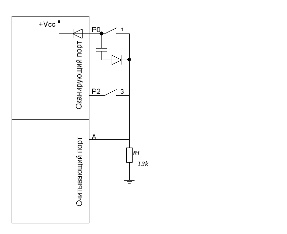
I found the first diode, soldered - and indeed, unauthorized button presses no longer occur. That's just the delay after the release of the left button disappeared. How so? And it’s very simple - as we already know, to trigger on input A there must be at least 0.7 supply voltage, that is, the entire bundle “capacitor + diode” must be no more than 0.75 volts. And on the diode, as you know, it drops about 0.7 volts, plus another capacitor - that's not enough voltage.
The Schottky diode will help us, the forward voltage drop on which is noticeably less than on a conventional diode.

Unfortunately, I could not find Schottky diodes, so I found the diode with the smallest voltage drop (multimeter showed 0.44 V) and soldered it cleanly to make sure that the proposed solution works. You can search for it on the KDPV (the hint is black and pink). I also had to raise the supply voltage to 3.3 V, but still the desired effect was achieved! The delay of releasing the button is as much as 0.4 seconds, and no button is pressed “for the company”. True, for obvious reasons, this structure had to be dismantled, but the main conclusion was made - Schottky diodes would save the father of Russian democracy.
That, in fact, is the end of the tale.
UPD: It turns out, and this is not the end. It is rightly indicated in kamenta that the given circuit with a diode cannot work, because the capacitor cannot discharge when the button is closed. And it worked, apparently, only because the capacitor was discharged through the resistance of the oscilloscope probe, equal to one megaoma. The following scheme is declared to be truly correct today:

That is, it is necessary to cut the track on the board leading from the switch to the “scanning” leg and solder the diode into the resulting cut. Well, or not necessarily to scan, the main thing - that the current could not flow to our scanning leg from one other scanning leg.
Probably, writing a third article on this topic is too much, so if I’m going to experiment with this scheme, I’ll add it here.
No, the button did not crumble to dust, as one of the commentators prophesied. And in general, none of those present guessed the fate of the long-suffering mouse, although, as I understand now, it was almost obvious.
')
On a tip from a respected ploop, I discovered the program xev , which among other things shows which buttons are pressed. I click the right button and see:
Oh God
 ButtonPress event, serial 56, synthetic NO, window 0xb200001,
     root 0x274, subw 0x0, time 3959640285, (43,112), root: (1109,578),
     state 0x10, button 1, same_screen YES

 ButtonPress event, serial 56, synthetic NO, window 0xb200001,
     root 0x274, subw 0x0, time 3959640285, (43,112), root: (1109,578),
     state 0x110, button 3, same_screen YES

 ButtonRelease event, serial 56, synthetic NO, window 0xb200001,
     root 0x274, subw 0x0, time 3959640436, (43,112), root: (1109,578),
     state 0x510, button 3, same_screen YES

 ButtonRelease event, serial 56, synthetic NO, window 0xb200001,
     root 0x274, subw 0x0, time 3959640452, (43,112), root: (1109,578),
     state 0x110, button 1, same_screen YES
That is, whenever I press the right button (3), the mouse thinks that the left button (1) is also pressed! At this point, I remembered that after reworking this mouse, it became impossible to bring up the context menu in the Chrome window header. Then I did not attach any importance to this, because at about the same time, moving back and forth with the “back and forth” buttons also fell off, and only on Habré / GT and only on the second mouse, which I (my mother swear) did nothing with.
Vypayav capacitor, I was convinced - indeed, it was he who was guilty of pressing the extra button. And this put an end to the whole idea of a panacea for bounce from the previous post. Since there was no wish to choose between habrassucicide and a deal with conscience, I had to think how to overcome this most unpleasant side effect. So again we disassemble the mouse, cut in the oscilloscope and try to achieve the very understanding that we lacked last time.
The mouse appeared to be based on the nRF24LE1 microcontroller well-known in the nation.
By dialing, it was found that all the breaker leads go straight to the feet of the processor, and each such leg is connected to more than one switch. More specifically, the scheme appears as follows:
(An asterisk button means a dpi change button that does not pass to the mouse exit.)
This makes it possible to suspect the authors in the application of the technique called “matrix keyboard” . The scanning signal is alternately transmitted to the legs and looks at which reading legs it appeared. This allows you to save legs - because the buttons in this way can be set in proportion to the square of the number of used legs. (In this case, we have 6 buttons and 5 conclusions - that is, the whole one leg is saved. However, I forgot to ring the wheel, so it is possible that the same circuit serves the wheel, then it means saving two legs.)
But for now this is only an assumption, you need to check it.
At P0, a pulse with a duration of 20 microseconds (indicated by an arrow) is applied, which comes to the leg A at a closed switch. It is not visible here, but the interval between pulses is about 10-15 milliseconds. So, software bounce protection is still present, and it becomes unclear how it turns out that it does not help. But back to our sheep and release the button:
As we expected, the scanning signal on the reading foot disappears. And now press the left and right buttons at the same time:
And again, in full accordance with expectations, we get two signals from the two legs at the output, separated in time. If you now press the middle button, there will be three signals that will merge into one big line.
But how is it that when two buttons are pressed, the scanning legs do not short out with each other and do not spoil the signal to each other? In the above article for this proposed to use diodes. Here everything is simpler - when the leg is inactive, it is transferred to the Hi-Z (high resistance) mode, that is, it is actually disconnected from the circuit, and no current flows through it. As evidence in favor of this - if, with the buttons open, inadvertently touch the scanning port, the oscilloscope will show the characteristic “wool” (that is, interference from the radio broadcast received by our body):
To finally confirm our guess, we set up an experiment. If the button presses are registered by increasing the voltage, then if you close the scanning port to power, the mouse should perceive this as pressing all the buttons on this port.
Close port A
 ButtonPress event, serial 166, synthetic NO, window 0xb200001,
     root 0x274, subw 0x0, time 4059940208, (547,509), root: (1297,734),
     state 0x10, button 6, same_screen YES

 ButtonRelease event, serial 166, synthetic NO, window 0xb200001,
     root 0x274, subw 0x0, time 4059940208, (547,509), root: (1297,734),
     state 0x10, button 6, same_screen YES

 ButtonPress event, serial 166, synthetic NO, window 0xb200001,
     root 0x274, subw 0x0, time 4059940208, (547,509), root: (1297,734),
     state 0x10, button 1, same_screen YES

 ButtonPress event, serial 166, synthetic NO, window 0xb200001,
     root 0x274, subw 0x0, time 4059940208, (547,509), root: (1297,734),
     state 0x110, button 3, same_screen YES

 ButtonPress event, serial 166, synthetic NO, window 0xb200001,
     root 0x274, subw 0x0, time 4059940208, (547,509), root: (1297,734),
     state 0x510, button 2, same_screen YES

 ButtonRelease event, serial 166, synthetic NO, window 0xb200001,
     root 0x274, subw 0x0, time 4059940253, (547,509), root: (1297,734),
     state 0x710, button 2, same_screen YES

 ButtonRelease event, serial 166, synthetic NO, window 0xb200001,
     root 0x274, subw 0x0, time 4059940268, (547,509), root: (1297,734),
     state 0x510, button 1, same_screen YES

 ButtonRelease event, serial 166, synthetic NO, window 0xb200001,
     root 0x274, subw 0x0, time 4059940268, (547,509), root: (1297,734),
     state 0x410, button 3, same_screen YES
Close port B
 ButtonPress event, serial 166, synthetic NO, window 0xb200001,
     root 0x274, subw 0x0, time 4059977818, (172.409), root: (922,634),
     state 0x10, button 7, same_screen YES

 ButtonRelease event, serial 166, synthetic NO, window 0xb200001,
     root 0x274, subw 0x0, time 4059977818, (172.409), root: (922,634),
     state 0x10, button 7, same_screen YES

 ButtonPress event, serial 166, synthetic NO, window 0xb200001,
     root 0x274, subw 0x0, time 4059977818, (172.409), root: (922,634),
     state 0x10, button 8, same_screen YES

 ButtonPress event, serial 166, synthetic NO, window 0xb200001,
     root 0x274, subw 0x0, time 4059977818, (172.409), root: (922,634),
     state 0x10, button 9, same_screen YES

 ButtonRelease event, serial 166, synthetic NO, window 0xb200001,
     root 0x274, subw 0x0, time 4059977950, (172.409), root: (922,634),
     state 0x10, button 8, same_screen YES

 ButtonRelease event, serial 166, synthetic NO, window 0xb200001,
     root 0x274, subw 0x0, time 4059977950, (172.409), root: (922,634),
     state 0x10, button 9, same_screen YES
Again, everything is as we expected, plus there were “Easter” buttons 6 and 7, which are not physically on the mouse (the wheel corresponds to buttons 4 and 5).
So, we know the truth about the mouse and its buttons. But how will this help us cope with our initial misfortune? To do this, we need to understand two more things - why the capacitor delays releasing the button and why it contributes to pressing it when another button is pressed.
When we close button 1, the capacitor instantly discharges, and the voltage on it becomes zero. As long as the button is pressed, the capacitor is shorted, so that the mouse perceives pressing the button as if there was no condenser.
Now let go of the button. Since the capacitor has a capacitance, the voltage on it is still zero. So, if we apply a scanning voltage (2.5 V power supply) to P0, then the input A will also have 2.5 volts, which corresponds to the pressed button.
However, with each such pulse, the capacitor will gradually be charged (through the resistance R1). And at one point, it will charge, say, up to 2 volts, and at the input A there will already be 0.5 volts, which is not enough for a unit to appear on this input. Therefore, some time after the button is released, the mouse will think that the button is still pressed, and then “understand” that it has been released.
You can even approximately estimate this time. Our RC chain consists of a 13 kΩ resistor and a capacitor, for example, 0.1 µF. Multiply these two values and find the characteristic time of 1.3 milliseconds. But since the current flows not all the time, but only 20 microseconds every 10 milliseconds, this time extends to 0.65 seconds - as we intended last time.
One could be delighted with such an exact coincidence of calculation with the experiment, but it is necessary to add another spoonful of tar. The point is that the characteristic time is the time during which the voltage drops to the number e, that is, 2.7 times. But the datasheet on nRF24LE1 tells us that Input high voltage is 0.7 VDD, and Input low voltage is 0.3 VDD. That is, the inputs of our processor work as a Schmitt trigger, and in order for them to perceive the unit, we need to raise the voltage to 0.7 supply voltage. Why did we take 0.7, not 0.3, you ask? It's very simple - since most of the time at input A is pure zero, then at the moment of impulse we need to raise the voltage to 0.7 supply, otherwise the Schmitt trigger will not switch to one. So calculation gives time
ln (0.7) / ln (1 / e) * 0.65 = 0.23 seconds.
And in fact, we have 0.6 seconds! If you subtract the time when the button is closed - it is 0.5 seconds, which is still a lot. To explain this, we can assume that in the Hi-Z mode, the leg resistance P0 is still not infinite, and “quietly” discharges the capacitor in the gap between the measuring pulses. Very roughly from our data, we can estimate its value - since it discharges a capacitor by 10 ms, an amount comparable to that it charges for 20 μs, this resistance is more than 6.5 megaohms.
And here we need to remember another fact, which I did not attach importance. Namely, if you solder a capacitor smaller than 2 nF, the mouse will think that the button is always pressed. And now this fact gets an explanation - in 10 milliseconds the capacitor has time to discharge (2 nF * 6.5 MΩ = 13 ms), so that with a Schmitt trigger, the trigger works, while this pulse is on, the capacitor is charged (2 nF * 13 kΩ = 26 microseconds), but does not have time to charge to such an extent as to overcome the threshold of 0.3 supply voltage.
Now let's see what happens when we press the right button, not the left button.
At rest on the capacitor we have 2.5 volts. Close switch 3 and wire 20 microsecond pulses from port P2 to conductor A. But if A 2.5 volts plus 2.5 volts on a capacitor, then P0 should have 5 volts on its leg! A controller is designed for no more than 3.6 volts. Especially for such cases in the chips provide protective diodes, so that the voltage at the inputs does not exceed the supply voltage:
So, as soon as the supply voltage appears on P2, the capacitor is discharged through this diode, and it will have 0.7 volts, or even less. And then it will be further discharged after 6.5 mega-ohms. And when it comes time to measure the pulse on the leg P0, the voltage on the capacitor will be so small that at input A there will be an almost full supply voltage and, as a result, a clear unit. So we got to press the left button when you press the right.
Now, finally, we answered all the questions from the “who's to blame” category, only a very small amount remains - what to do? Since the root of our trouble in discharging a capacitor, we put a barrier in the form of a diode in the path of this current:
I found the first diode, soldered - and indeed, unauthorized button presses no longer occur. That's just the delay after the release of the left button disappeared. How so? And it’s very simple - as we already know, to trigger on input A there must be at least 0.7 supply voltage, that is, the entire bundle “capacitor + diode” must be no more than 0.75 volts. And on the diode, as you know, it drops about 0.7 volts, plus another capacitor - that's not enough voltage.
The Schottky diode will help us, the forward voltage drop on which is noticeably less than on a conventional diode.
Unfortunately, I could not find Schottky diodes, so I found the diode with the smallest voltage drop (multimeter showed 0.44 V) and soldered it cleanly to make sure that the proposed solution works. You can search for it on the KDPV (the hint is black and pink). I also had to raise the supply voltage to 3.3 V, but still the desired effect was achieved! The delay of releasing the button is as much as 0.4 seconds, and no button is pressed “for the company”. True, for obvious reasons, this structure had to be dismantled, but the main conclusion was made - Schottky diodes would save the father of Russian democracy.
That, in fact, is the end of the tale.
UPD: It turns out, and this is not the end. It is rightly indicated in kamenta that the given circuit with a diode cannot work, because the capacitor cannot discharge when the button is closed. And it worked, apparently, only because the capacitor was discharged through the resistance of the oscilloscope probe, equal to one megaoma. The following scheme is declared to be truly correct today:
That is, it is necessary to cut the track on the board leading from the switch to the “scanning” leg and solder the diode into the resulting cut. Well, or not necessarily to scan, the main thing - that the current could not flow to our scanning leg from one other scanning leg.
Probably, writing a third article on this topic is too much, so if I’m going to experiment with this scheme, I’ll add it here.
Source: https://habr.com/ru/post/366247/
All Articles