Smart home or toy for men: end devices
In one of my previous articles , a survey was conducted on the most interesting topic for readers: "End devices of a smart home (installation, connection, use ...)". 80% of readers voted for it. This article will be devoted to a general description of the main end devices with detailed links to information from the manufacturer.
The plan of the 1st floor shows the real devices of a real smart home:

')
The plan contains all the devices of a smart home: these are temperature and humidity sensors, current sensors, light sensors, water flow meters, voltage sensors, sensor controllers, smart sockets, etc.
Below for the sake of interest, you can see floor plans.
Returning to my first article , I want to remind readers that I am a supporter of the definition of a smart home given in Wikipedia , i.e. no frills: without a tender voice speaking to quiet music about the end of the sausage in the fridge, without automatic opening of gates and doors, etc. Comfort is the goal. Climate comfort first. The rest - you can play. You can automate watering of greenhouses and / or vegetable gardens, heat greenhouses, open-close curtains, windows and doors. But this, in my opinion, is not the main thing. Without this, the house will survive the cold at -30 ° C.
In this article I want to briefly describe the main, in my opinion, smart home devices. Therefore, we define the main devices:
Smart home - a thing that requires the highest reliability. It is clear that you need to duplicate it with other systems. But high requirements should still apply to him, since do not ride in the winter out of town for every nonsense. Therefore, I decided for myself that the server will work under Linux. Not yet regretted it. Raise any stable version of Linux. MFI controller is on the developer site . Installing the controller should not cause big problems.
The appearance of the device is varied.
At this point, everyone will think of himself.
Managed sockets are 3 types by the number of consumers for 1, 3 and 6 outlets.
 MPower Mini Socket
 Managed mPower socket for 3 consumers
 And mPower Pro socket for 6 consumers
Documentation for mPower mini, for mPower and for mPower Pro .
The difference in use is obvious, but at a cost of 2 mPower mini cost almost as much as 1 mPower Pro 6x (approximately 6000r versus 7300r), but more expensive than 1mPower 3x (6000r versus 4500).
Sockets mPower mini and mPower (for 1 and 3 consumers) work only through WiFi. mPower mini is inserted into a regular outlet. The mPower Pro socket on 6 consumers can be connected to the network via twisted pair. All controlled sockets are engaged in switching on and off equipment, collecting statistics on Watts, kW-hours, Amps, Volts, on-off. They can also work autonomously.
An example of using mPower mini was in the picture below.

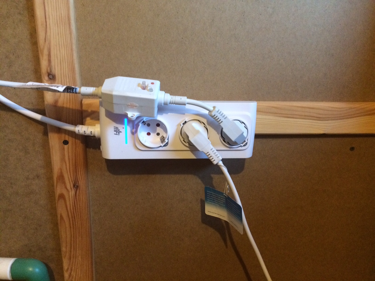
If you plan to use 2 controlled sockets nearby, then it makes sense to use mPower on 3 sockets, fixing it, for example, on the wall.
But the photo below is connected to the boiler and heater in the guest house:
If there is a shortage of 3, then it is more economical to use mPower Pro for 6 consumers. Strangely enough, it really is necessary in any control centers. I use it for 2 heaters, electric kettle (spot), TV, music center and electric grill in the gas stove. They totally do not exceed 16A. And, of course, I do not plan to use mPower Pro to its fullest under 16A for a long time. Heaters no more than 500W, kettle 800W per day, 1700W grill. The rest is totally no more than 100W.
Here is an example of its installation:

Installing and connecting them to the controller also should not cause problems. We turn on the outlet, after a minute or two we connect to WiFi, which they distribute, set your WiFi parameters, address, port, username and password to access the controller, and everything works. The documentation on the site describes everything in detail.

Some features of their use. Manufacturer Ubiquiti pretty high quality makes their products. But, there will always be skilled knobs who want to turn off or reboot the device when updating the firmware. In no case should this be done. Although a smart manufacturer, but such things are dangerous to do. Wait until the blue light stops flashing , wait another couple of minutes, and only then the outlet can be turned off. This applies to all equipment, not just outlets.
Judging by the survey in the previous article, the quality of electricity in country houses at 1/3 of readers is poor. Therefore, sockets may hang. In a couple of years I had 2-3 such cases. A simple software reset does not help, you need to de-energize it and turn it back on. In such cases, also helps to completely disconnect the house from electricity. According to the survey, most readers turn off electricity at least several times a year. And 28% of those who voted so lucky in general - several times a month.
In the greenhouses I have these sockets. Humidity there often approaches 100%, although according to the documentation they should be used at humidity up to 90% without condensate. 2 years hold on. The safety margin is enough.

mPower mini and mPower are designed for a load of 15A per outlet and 15A total.
mPower Pro is designed for 16A load per outlet and 16A total. This, too, must be borne in mind. 16 amps (at a voltage of 220V) multiplied by 0.22, we get 3.52 kW. What is written on the box with the equipment, as a rule, is not true and is written with a margin. A heater with 1.8kW can actually consume 1.5kW. And even less if the network voltage is low. The equipment, although reliable, is better not to subject it to long-term use at maximum loads.
I am in favor of using 2 heaters of 500W each, than one 1 kW, because I can manage them 2 by 500W, not 1 by kilowatt. When it is very cold, you can turn on 2 * 500W, and when you just need to keep warm, you can turn on only 1 per 500W. Similarly, I use a boiler. Usually I have only one heater included in it. And only when there are a lot of people, I turn it on to the full. Electricity in my house was conducted by a professional electrician, but still I do not want to use the maximum load on one outlet and one automatic device. In addition, 2 heaters of 500W will uniformly heat the room in different places than one per 1 kW in one place. In the offseason, one of them can simply be put away in the pantry before winter.
Next - temperature and humidity sensors. In fact, physically it is one sensor.
 Magnified view
The documentation is here.
Some important characteristics:
Some useful knowledge about temperature measurement. According to the rules, temperature sensors should be installed only on the internal walls, away from the equipment, at a height of 1.5-2 m. In practice, this is not always the case. It should be borne in mind that the measured temperature is true only for the place where it was measured, and not for where you would like. I will explain.
On the street within 2 weeks -30 ° C. The room was +8, just warmed up to + 20 ° C. The question is, what is the temperature under the corner cabinet in the corner of the external walls near the floor? Of course, it depends on the quality of the house insulation, on the time when the temperature has risen to 20 ° C and on many other conditions. I have in such conditions (with a rather good house insulation) in this corner the water in the supply pipe with cold water is frozen! I measured the temperature there with a laser thermometer, it turned out to be -10 ° C!
So you need to understand what we measure, where we measure and what we want. Temperature is not humidity. She is in no hurry to spread around the room. Yes, and on the 2nd floor rises slowly. All the time something hinders her. Humidity (like odors), on the contrary, spreads very quickly in all directions. According to humidity drops, you can quite accurately tell when a window or door was open. And also when the wife went to make breakfast or lunch.

The graph shows that at 13:06 the humidity started to rise, then the temperature. This indicates the beginning of cooking dinner. Then there was a failure in humidity, the temperature stopped growing rapidly, this is most likely due to the inclusion of a fan blowing from the kitchen into the corridor. The smart home realized that it was possible to cool the kitchen by bringing heat to the corridor, because it was not hot there. Then she, however, went up again.Just like a dollar to a ruble. A fan for some reason decided not to turn on. Then, judging by the drop in temperature and humidity, the cooking was over.
The temperature sensor, as already mentioned above, is also a humidity sensor. The pinout is shown below the spoiler, i.e. how to take humidity readings from this sensor. Appearance and information is available on the manufacturer’s website , although moisture measurement is not a documented feature.
Maybe because the manufacturer does not declare the possibility of measuring humidity, which is a weak point in these sensors. Over 2 years of using about 50 of these sensors, pieces 4-5 ceased to show humidity correctly. Humidity in greenhouses, I think, it is better not to measure. Several of these sensors are on my street for more than 2 years all year round. One has stopped to show humidity correctly. Replaced. Now the year is working fine.
To control the quality of measurements, I use a simple meteorological station (for 1500r) with two sensors: street and internal. The accuracy of determining the temperature and humidity is quite high. Same ± 0.5 ° C and ± 5% humidity. Sensors are nearby.
A very important sensor is the current sensor.
 Current sensor, click to view documentation.
It connects to any conductor and measures current consumption in Amps. How to recalculate in W, it was described above. It is noteworthy that having 1 phase, you can measure only it, and, having 3 phases, you can measure everything separately and in total on the core with the ground. And you can measure any individual machine, for example, the total consumption in the bath and / or in the guest house.
Practically everyone has the need to measure total consumption and consumption for individual machines. Few people have 2 electricity inputs to a plot of 3 phases of 50A each. I know only one such. But we are not talking about them now. And about those who have 25-40A on one phase or 3 * 25A on 3 phases. They should not exceed these values, since the incoming machines will turn off on a cold winter night, and you will go to the cottage on the same night so as not to freeze the house and water.
Smart home can count this expense and disable non-priority loads. Below are the rules for shutting down non-priority loads when thresholds are exceeded:

According to this rule, heaters in water-free rooms and a boiler are turned off. They will turn on later when the total consumption is reduced to the appropriate value. Now you can not be afraid that the machines will turn off fromoverdose .
The sensor is turned on to the mPort sensor controller and no further configuration is required. You just need to tell mPort what was stuck in it.
Now about the sensor controller.
 Sensor controller, click to enlarge the picture.
The documentation is here .
Some specifications:
And I repeat. The manufacturer is reinsured and mPort actually works all year round at a temperature of -35 ° C in winter and almost 100% humidity in summer. True, I think, he still can not stand the condensate. Therefore, you should not bring it from the frost into the house and immediately connect it to the outlet, it will burn with a high probability.
It is clear from the title that it is intended to collect information from sensors and some device control (but this is not in this article). In mPort no more than 3 sensors can be connected: 2 via RJ-45 and one more. It receives power via POE through the supplied adapter or via a POE switch. Accordingly, we can power it up, say, at the top of the cabinet and through the cable channel, let twisted pair to the sensor (as shown in one of the pictures above). Connecting mPower to the MFI smart home controller is also not a problem. Connect to it with a twisted pair, go to the address 192.168.1.20 (of course, your computer must be on the same subnet and 1.20 should be free), we report the parameters of the MFI controller. If there is a DHCP in the local network, then go straight to the desired address (you can find it in the list of issued addresses by MAC address).
Usually I immediately set up a WiFi connection, because The likelihood that I will use it over WiFi is very high. And it can be used both on twisted pair and on WiFi at will.
This article describes the work of the main devices of the smart home from Ubiquiti: temperature and humidity sensor, current sensor, sensor controller and smart sockets. Exact information on the connection is in the documentation, to which I left a lot of direct links. Problems with the network, WiFi, DHCP, etc. This article can not be parsed. The reader must have basic TCP / IP knowledge. Server issue is not considered here either. Also deliberately not considered the possibility of autonomous operation of controlled outlets, because The same weekly timer is several times cheaper.
Published the following article .
The plan of the 1st floor shows the real devices of a real smart home:
')
The plan contains all the devices of a smart home: these are temperature and humidity sensors, current sensors, light sensors, water flow meters, voltage sensors, sensor controllers, smart sockets, etc.
Below for the sake of interest, you can see floor plans.
2nd floor plan
Basement plan
Returning to my first article , I want to remind readers that I am a supporter of the definition of a smart home given in Wikipedia , i.e. no frills: without a tender voice speaking to quiet music about the end of the sausage in the fridge, without automatic opening of gates and doors, etc. Comfort is the goal. Climate comfort first. The rest - you can play. You can automate watering of greenhouses and / or vegetable gardens, heat greenhouses, open-close curtains, windows and doors. But this, in my opinion, is not the main thing. Without this, the house will survive the cold at -30 ° C.
In this article I want to briefly describe the main, in my opinion, smart home devices. Therefore, we define the main devices:
- smart sockets
- temperature and humidity sensor
- current sensor
- sensor controller (mPort)
Smart home - a thing that requires the highest reliability. It is clear that you need to duplicate it with other systems. But high requirements should still apply to him, since do not ride in the winter out of town for every nonsense. Therefore, I decided for myself that the server will work under Linux. Not yet regretted it. Raise any stable version of Linux. MFI controller is on the developer site . Installing the controller should not cause big problems.
The appearance of the device is varied.
From simple scatter on the table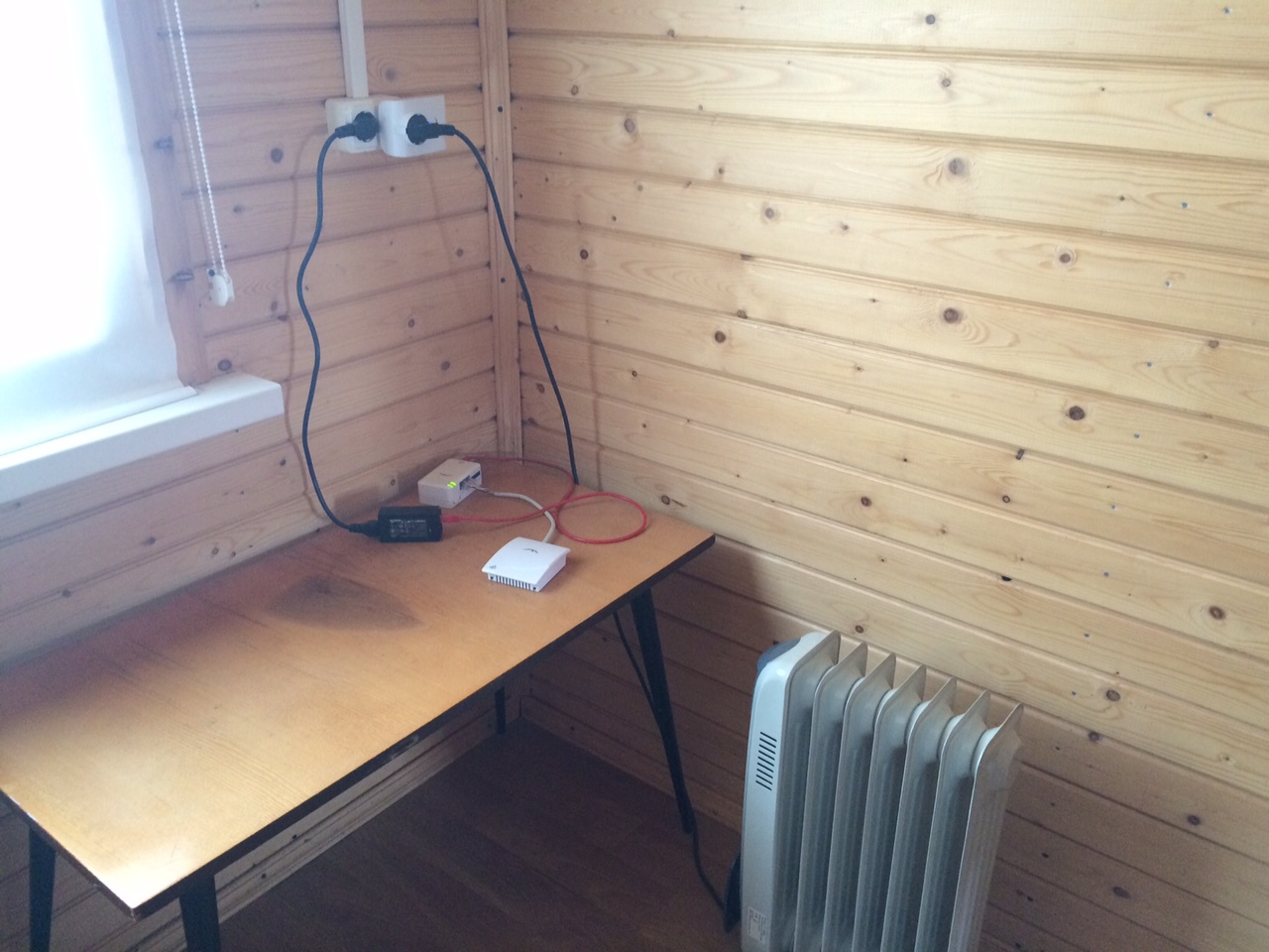
Or hanging on the wall
Cable ducting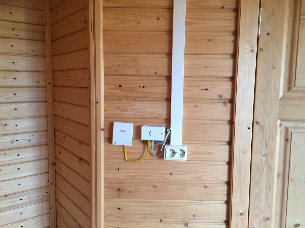
Or so
Or even in some box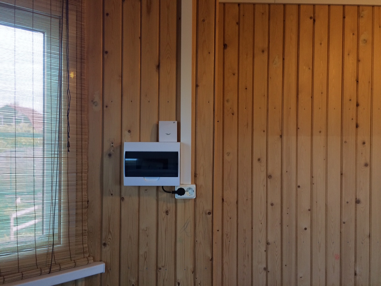
At this point, everyone will think of himself.
Managed sockets are 3 types by the number of consumers for 1, 3 and 6 outlets.
MPower Mini Socket Managed mPower socket for 3 consumers And mPower Pro socket for 6 consumers Documentation for mPower mini, for mPower and for mPower Pro .
The difference in use is obvious, but at a cost of 2 mPower mini cost almost as much as 1 mPower Pro 6x (approximately 6000r versus 7300r), but more expensive than 1mPower 3x (6000r versus 4500).
Sockets mPower mini and mPower (for 1 and 3 consumers) work only through WiFi. mPower mini is inserted into a regular outlet. The mPower Pro socket on 6 consumers can be connected to the network via twisted pair. All controlled sockets are engaged in switching on and off equipment, collecting statistics on Watts, kW-hours, Amps, Volts, on-off. They can also work autonomously.
An example of using mPower mini was in the picture below.
If you plan to use 2 controlled sockets nearby, then it makes sense to use mPower on 3 sockets, fixing it, for example, on the wall.
But the photo below is connected to the boiler and heater in the guest house:
If there is a shortage of 3, then it is more economical to use mPower Pro for 6 consumers. Strangely enough, it really is necessary in any control centers. I use it for 2 heaters, electric kettle (spot), TV, music center and electric grill in the gas stove. They totally do not exceed 16A. And, of course, I do not plan to use mPower Pro to its fullest under 16A for a long time. Heaters no more than 500W, kettle 800W per day, 1700W grill. The rest is totally no more than 100W.
Here is an example of its installation:
Installing and connecting them to the controller also should not cause problems. We turn on the outlet, after a minute or two we connect to WiFi, which they distribute, set your WiFi parameters, address, port, username and password to access the controller, and everything works. The documentation on the site describes everything in detail.
Some features of their use. Manufacturer Ubiquiti pretty high quality makes their products. But, there will always be skilled knobs who want to turn off or reboot the device when updating the firmware. In no case should this be done. Although a smart manufacturer, but such things are dangerous to do. Wait until the blue light stops flashing , wait another couple of minutes, and only then the outlet can be turned off. This applies to all equipment, not just outlets.
Judging by the survey in the previous article, the quality of electricity in country houses at 1/3 of readers is poor. Therefore, sockets may hang. In a couple of years I had 2-3 such cases. A simple software reset does not help, you need to de-energize it and turn it back on. In such cases, also helps to completely disconnect the house from electricity. According to the survey, most readers turn off electricity at least several times a year. And 28% of those who voted so lucky in general - several times a month.
In the greenhouses I have these sockets. Humidity there often approaches 100%, although according to the documentation they should be used at humidity up to 90% without condensate. 2 years hold on. The safety margin is enough.
mPower mini and mPower are designed for a load of 15A per outlet and 15A total.
mPower Pro is designed for 16A load per outlet and 16A total. This, too, must be borne in mind. 16 amps (at a voltage of 220V) multiplied by 0.22, we get 3.52 kW. What is written on the box with the equipment, as a rule, is not true and is written with a margin. A heater with 1.8kW can actually consume 1.5kW. And even less if the network voltage is low. The equipment, although reliable, is better not to subject it to long-term use at maximum loads.
I am in favor of using 2 heaters of 500W each, than one 1 kW, because I can manage them 2 by 500W, not 1 by kilowatt. When it is very cold, you can turn on 2 * 500W, and when you just need to keep warm, you can turn on only 1 per 500W. Similarly, I use a boiler. Usually I have only one heater included in it. And only when there are a lot of people, I turn it on to the full. Electricity in my house was conducted by a professional electrician, but still I do not want to use the maximum load on one outlet and one automatic device. In addition, 2 heaters of 500W will uniformly heat the room in different places than one per 1 kW in one place. In the offseason, one of them can simply be put away in the pantry before winter.
Next - temperature and humidity sensors. In fact, physically it is one sensor.
Magnified view The documentation is here.
Some important characteristics:
- capacity to 0.01 ° C
- temperature measurement accuracy (according to documentation) ± 0.5 ° ,
- ± 3% humidity measurement accuracy
- temperature measurement range from -10 to + 50 °
- can work at relative humidity not more than 95%, without condensate
Some useful knowledge about temperature measurement. According to the rules, temperature sensors should be installed only on the internal walls, away from the equipment, at a height of 1.5-2 m. In practice, this is not always the case. It should be borne in mind that the measured temperature is true only for the place where it was measured, and not for where you would like. I will explain.
On the street within 2 weeks -30 ° C. The room was +8, just warmed up to + 20 ° C. The question is, what is the temperature under the corner cabinet in the corner of the external walls near the floor? Of course, it depends on the quality of the house insulation, on the time when the temperature has risen to 20 ° C and on many other conditions. I have in such conditions (with a rather good house insulation) in this corner the water in the supply pipe with cold water is frozen! I measured the temperature there with a laser thermometer, it turned out to be -10 ° C!
So you need to understand what we measure, where we measure and what we want. Temperature is not humidity. She is in no hurry to spread around the room. Yes, and on the 2nd floor rises slowly. All the time something hinders her. Humidity (like odors), on the contrary, spreads very quickly in all directions. According to humidity drops, you can quite accurately tell when a window or door was open. And also when the wife went to make breakfast or lunch.
The graph shows that at 13:06 the humidity started to rise, then the temperature. This indicates the beginning of cooking dinner. Then there was a failure in humidity, the temperature stopped growing rapidly, this is most likely due to the inclusion of a fan blowing from the kitchen into the corridor. The smart home realized that it was possible to cool the kitchen by bringing heat to the corridor, because it was not hot there. Then she, however, went up again.
The temperature sensor, as already mentioned above, is also a humidity sensor. The pinout is shown below the spoiler, i.e. how to take humidity readings from this sensor. Appearance and information is available on the manufacturer’s website , although moisture measurement is not a documented feature.
Pinout under spoiler
Maybe because the manufacturer does not declare the possibility of measuring humidity, which is a weak point in these sensors. Over 2 years of using about 50 of these sensors, pieces 4-5 ceased to show humidity correctly. Humidity in greenhouses, I think, it is better not to measure. Several of these sensors are on my street for more than 2 years all year round. One has stopped to show humidity correctly. Replaced. Now the year is working fine.
To control the quality of measurements, I use a simple meteorological station (for 1500r) with two sensors: street and internal. The accuracy of determining the temperature and humidity is quite high. Same ± 0.5 ° C and ± 5% humidity. Sensors are nearby.
A very important sensor is the current sensor.
Current sensor, click to view documentation. It connects to any conductor and measures current consumption in Amps. How to recalculate in W, it was described above. It is noteworthy that having 1 phase, you can measure only it, and, having 3 phases, you can measure everything separately and in total on the core with the ground. And you can measure any individual machine, for example, the total consumption in the bath and / or in the guest house.
An example of the installation of a current sensor at the entrance to the house under the spoiler:
Installation example of a current sensor for a guest house:
Practically everyone has the need to measure total consumption and consumption for individual machines. Few people have 2 electricity inputs to a plot of 3 phases of 50A each. I know only one such. But we are not talking about them now. And about those who have 25-40A on one phase or 3 * 25A on 3 phases. They should not exceed these values, since the incoming machines will turn off on a cold winter night, and you will go to the cottage on the same night so as not to freeze the house and water.
Smart home can count this expense and disable non-priority loads. Below are the rules for shutting down non-priority loads when thresholds are exceeded:
According to this rule, heaters in water-free rooms and a boiler are turned off. They will turn on later when the total consumption is reduced to the appropriate value. Now you can not be afraid that the machines will turn off from
The sensor is turned on to the mPort sensor controller and no further configuration is required. You just need to tell mPort what was stuck in it.
Now about the sensor controller.
Sensor controller, click to enlarge the picture. The documentation is here .
Some specifications:
- temperature measurement range from -10 to + 70 °
- can work at relative humidity not more than 80%, without condensate
And I repeat. The manufacturer is reinsured and mPort actually works all year round at a temperature of -35 ° C in winter and almost 100% humidity in summer. True, I think, he still can not stand the condensate. Therefore, you should not bring it from the frost into the house and immediately connect it to the outlet, it will burn with a high probability.
It is clear from the title that it is intended to collect information from sensors and some device control (but this is not in this article). In mPort no more than 3 sensors can be connected: 2 via RJ-45 and one more. It receives power via POE through the supplied adapter or via a POE switch. Accordingly, we can power it up, say, at the top of the cabinet and through the cable channel, let twisted pair to the sensor (as shown in one of the pictures above). Connecting mPower to the MFI smart home controller is also not a problem. Connect to it with a twisted pair, go to the address 192.168.1.20 (of course, your computer must be on the same subnet and 1.20 should be free), we report the parameters of the MFI controller. If there is a DHCP in the local network, then go straight to the desired address (you can find it in the list of issued addresses by MAC address).
The configuration picture of the controller under the spoiler.
Usually I immediately set up a WiFi connection, because The likelihood that I will use it over WiFi is very high. And it can be used both on twisted pair and on WiFi at will.
This article describes the work of the main devices of the smart home from Ubiquiti: temperature and humidity sensor, current sensor, sensor controller and smart sockets. Exact information on the connection is in the documentation, to which I left a lot of direct links. Problems with the network, WiFi, DHCP, etc. This article can not be parsed. The reader must have basic TCP / IP knowledge. Server issue is not considered here either. Also deliberately not considered the possibility of autonomous operation of controlled outlets, because The same weekly timer is several times cheaper.
Published the following article .
Source: https://habr.com/ru/post/366239/
All Articles