Shin Muscle Amplifier
I want to tell you about my idea and how I tried to bring it to life. The device is an amplifier of the leg muscles (ankle), which works on the principle of energy storage in the spring. In the article I tried to describe the entire path that has passed. I also want to say that this was my first experience in the field of working with real construction, and also this is my graduation project.
When I was a student at MSTU. Bauman, acrobatics, and in general he loved complex coordination sports (and still love). Around 2007, I found a device on the Internet that helps a person to jump and run high. Its name is JollyJumper . In fact, it was a spring rigidly attached to the human ankle. In this case, the ankle (foot relative to the lower leg and tarsus) is rigidly fixed.

')
This version of the design can be called a trampoline analogue. The user cannot control his jumps by the movement of the ankle, as it happens when jumping on a gymnastic mat or acrobatic track.
I will not say much about the dimensions, weight and use for walking and running, but they are also not particularly outstanding. For example, when you walk or run for the first time, you will touch the springs against each other.
I had an idea: if there is an analogue of a trampoline, then maybe there is an analogue of an acrobatic track? I started to google and found a few devices for jumping:
1) TRAMP-It-Jump-Shoes (in 2007 they were only abroad):

2) Kango Jumps (in 2007 they were only abroad):

3) Designed by Essur Kristinsson (Össur Kristinsson). Name: Cheetah Flex-Foot. These prostheses use Oscar Pistorius

But all these devices did not allow the ankle to move.
Later, I conducted another patent search. There I discovered many more interesting things, but more on that later. I want to describe the process as it was.
This was my course research paper (KNIRS). I offered it to my supervisor and he approved, for which he thanks a lot! Since my department instrumental engineering and technology - then the theme should have been relevant. But I was turned out by the fact that I developed the manufacturing technology of this design and, accordingly, I calculated the processing modes.
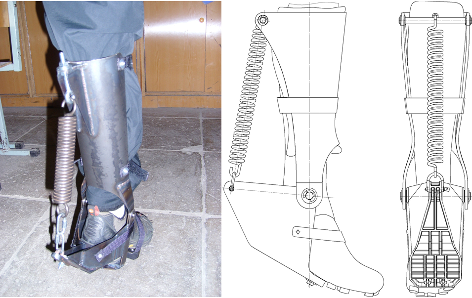
The device that I developed consists of a foot (red), a calf clamp (black), a metatarsus (black, is in contact with the floor), and a spring (turquoise). The leg (blue) is attached to the device with the help of straps (gray). Between the foot and the calf latch, it is desirable to place a piece of felt so that the latch does not rub the leg.

The foot can rotate relative to the calf lock. The axis of rotation is shown in the figure, it is aligned with the axis of rotation of the foot relative to the lower leg (ankle).
In the relaxed position, the spring is in a compressed state. Stop drawn. When the foot “pulls” on itself, the spring stretches and creates a force that tends to pull off the foot.
Metatarsus can rotate freely (pull on itself and away from itself). So you can stand still and walk. However, it is possible to make a device with a rigid, non-rotating keyhole. This design will be less convenient when walking and standing, but can transfer more power by using a larger spring stroke.
The device does not replace the force that is created by the muscles of the agonists of the leg, namely, it increases it, gives an increase in strength to it. At the same time, the maneuverability of movements will remain almost completely.
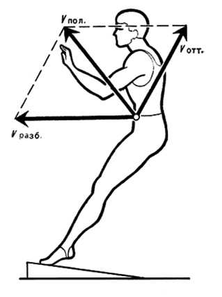
The scheme of work is as follows:

I - The moment of flight (fall). A person jumps from a height, or from a previous jump.
II-III - moment of touch. Running sock legs. From the drawn position it goes to the horizontal.
III-V - Spring tension. At this period, the strength of the calf muscles is added to the force from the spring. Also at this stage there is a quenching of the fall effort (depreciation). The force from the spring takes some of the load on itself. In position V, the spring is stretched to the maximum.
V-VIII - Spring compression. The calf muscles contract and give strength to the jump. To this force is added the force from the compression of the spring. Therefore the repulsive force increases.
VIII-IX - Finalizing socks. At this point, the final pushing is due to delaying the toe. This pushing sets the direction of flight of the foot (in conjunction with the work of the hands, the deviation of the body and the work of the thigh muscles). Also drawn socks are the result of proper operation when pushing away during a jump.
The first thing developed the appearance. That is approximately described the kinematic scheme. I used MathCad to calculate the optimal geometry and spring stiffness. That is, such a geometry that would give the maximum efficiency from use.
To determine the moment, the equation of moment relative to the point of rotation of the foot relative to the lower leg was compiled:
M = d ∙ F, where d is the shoulder, F = k ∙ x is the force created by the spring.
k - spring stiffness, x - spring tension.
Next, it was necessary to obtain the dependence of the moment M on the angle of rotation ω.
The dependence of the length of the shoulder on the angle of rotation:

The dependence of the spring tension on the angle of rotation:

where H - the length of the spring in the relaxed state.
The general equation of moment depending on the angle of rotation:

Next, a graph of the dependence of the moment on the angle of rotation (in radians):

From this graph, I found that the most optimal use of the structure at an angle of rotation from 60◦ to 100◦.
The prototype was designed using a CATIA V5 R19 system. The strength characteristics of its parts were calculated. The material of case parts is steel 3. The thickness of the sheet from which these parts were made is 2 mm.


Since I was a poor student, I didn’t have much money. Almost all operations had to be performed by professionals. And in order for Uncle Vasya to do what I want right the first time, it is necessary to describe the detail so that it is understandable and hedgehog. I made drawings of all parts, assembling parts with all allowances and so on. As a result, at first I was cut out a sheet at the factory where I was practicing. Cutting the sheet took place on an EDM machine (wire) Fanuc. Yeah ... I probably do not even know how to create a technical process even more expensive. In any case, it came out to me very cheaply, as an acquaintance. Although the wire was used new (!!!), as the machine is designed in such a way that the waste wire breaks. This was done so that the wire could not be used again, and also it was easier to recycle it and blah blah blah ... Of course, this can be turned off, but then the warranty for the machine flies. This machine was used for very precise operations, stood in a special thermostabilized room. Also, at the factory, I was machined and hardened axles.

At the institute, I was introduced to a welder. Bending parts I made myself. The welding process took about 3 days. Countersink and reamer holes, riveting straps and drilling holes I did myself in my chair. The diameter of the axis was chosen based on the availability of a suitable tool. That is, at first I found suitable tools (drill-countersink drill-through), and then I created an axis drawing (see figure above). I ordered the spring at Lianozovo Research Institute of Special Steels. I was just surprised that the two springs according to my drawings cost me only 250 rubles! Moreover, they even gave me checks, which actually confirmed the conformity of the product and the drawing.


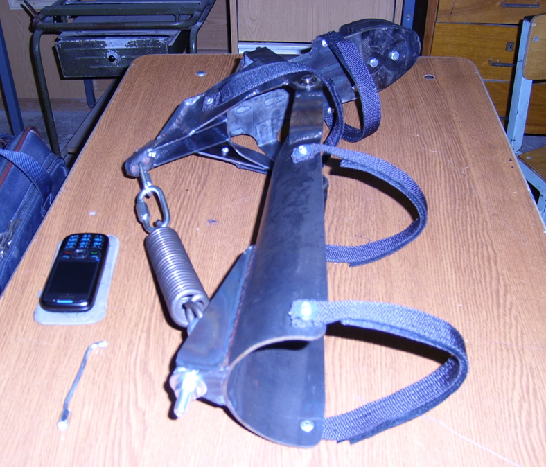

After creating the structure, several errors were revealed:
- the spring was very tough (2000 n);
- the hinge axis is further (relative to the heel) than the ankle joint axis by about 10-15 mm;
- The length of the footplate is not sufficient for the foot to fully stand. The toe of the foot hangs down from the footplate (about 15 mm), which creates some discomfort;
- non-ergonomic sock rubber buffer geometry. It is necessary to make more rounded shapes and a larger radius of curvature;
- in zone A there is a concentration of effort (reaction) on the shin.
In general, the prototype showed that the design is workable. Construction weight (on one leg) 3 kg.

At the beginning, a medium-sized man’s foot and a bicycle contact shoe were modeled. Contact boots have a very hard composite sole. Hard outsole is a carrier of force from the toe to the spring through the foot lock. For more accurate modeling, I decided to make a 3D model of my leg. I photographed my leg in two projections and created a 3D model based on these projections (by the way, this approach is often used in China to quickly create 3D copies of products and subsequent production).
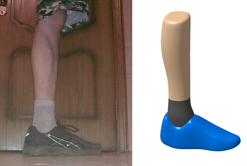
A lot of options were worked out, one of them was a version with a regular sneaker.
Further, according to the sneaker model and legs, two main parts were created: a foot lock and a calf lock. A purely technical 3D model of the whole structure was created, as there was not enough time.

Polycarbonate PC-LSV-30 was designated as the construction material, since it satisfied the strength and the formability and casting characteristics.
Were carried out the simplest calculations for the strength of the structure. The goal is to find out how the footplate is “moving out” in the hinged places. The calculation showed satisfactory results. Equivalent voltages stock was also available.

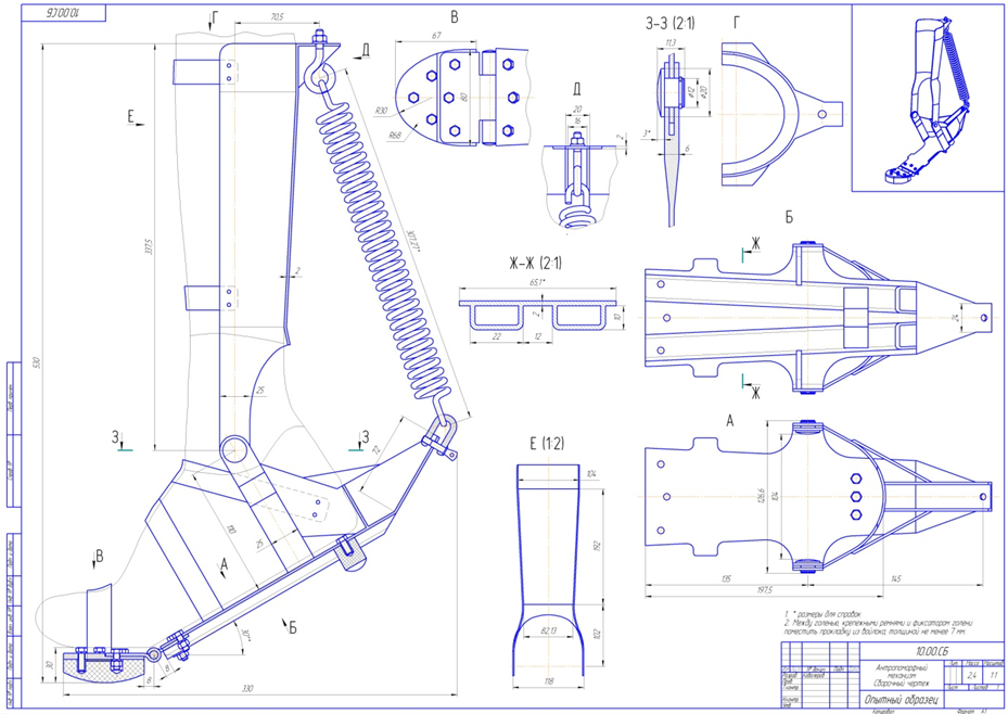
Then I didn’t have time to do a beautiful model (with fasteners and inner lining) of the general assembly, so here I will give a drawing of the general view of my design on the human foot.

Since I studied at the department of instrumental engineering and technology, the main part of my diploma was in the technology of making my design.
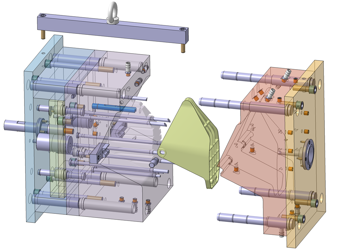
I considered a variety of manufacturing options and a variety of forms of forms: silicone, created by spraying, etc. As a result, stopped at the classic version. In the module CATIA Molding Design has developed a mold for the manufacture of footplate. The form was created from standard Hasco components (since CATIA had their library, and their components were too lazy to create, and there was no time). When designing the cooling system, it was necessary to use specific details (seemingly of Fodesco) for the desired distribution of the flow of cooling / heating fluid. To reduce the cost of production (circulation of a small 1000 pieces per month) marks for molding holes made overlaid with manual notch. Now I realized that it would be possible to add embedded elements to the structure in the axis area, but I did not do this on a diploma.
By the way, my form was examined by mold designers, who said that it was created correctly and technologically, that is, it could already have been made. At the cost of manufacturing the form, it turned out about 7,000 euros (2010).
Next was created the technological process of manufacturing the matrix. That is, the selection of tools, processing modes, the choice of equipment, machines, etc. I will not give here the operational sketches, because I do not think it will be of interest.
The result of the work done showed that the design is workable. At that time I had little money, so I could not translate my idea into reality.
The project considered a large number of options and conducted a patent search, which gave interesting results, and also introduced me to the German doctor Gerd Jungkunz. Then, by some miracle, I found his e-mail on the Internet and talked to him a little about his models. It turned out that he created almost the same design and even somehow tried it (he had only a garage and tools of a grinder level at his disposal, after all he was a doctor of medicine). Nevertheless, the work did not go further, and he abandoned the case. Now I have lost his contacts, and my recent searches have been fruitless. Can anyone help? ..
Below is my selection of interesting patents on the topic:


Now I am considering options with more productive elastic materials as a spring and the ability to make the design more ergonomic.
If someone is interested in my work, I am ready to cooperate, as well as the whole topic of exoskeletons and various kinds of amplifiers of human power is interesting to me.
Idea
When I was a student at MSTU. Bauman, acrobatics, and in general he loved complex coordination sports (and still love). Around 2007, I found a device on the Internet that helps a person to jump and run high. Its name is JollyJumper . In fact, it was a spring rigidly attached to the human ankle. In this case, the ankle (foot relative to the lower leg and tarsus) is rigidly fixed.
')
This version of the design can be called a trampoline analogue. The user cannot control his jumps by the movement of the ankle, as it happens when jumping on a gymnastic mat or acrobatic track.
I will not say much about the dimensions, weight and use for walking and running, but they are also not particularly outstanding. For example, when you walk or run for the first time, you will touch the springs against each other.
I had an idea: if there is an analogue of a trampoline, then maybe there is an analogue of an acrobatic track? I started to google and found a few devices for jumping:
1) TRAMP-It-Jump-Shoes (in 2007 they were only abroad):
2) Kango Jumps (in 2007 they were only abroad):
3) Designed by Essur Kristinsson (Össur Kristinsson). Name: Cheetah Flex-Foot. These prostheses use Oscar Pistorius
But all these devices did not allow the ankle to move.
Later, I conducted another patent search. There I discovered many more interesting things, but more on that later. I want to describe the process as it was.
Prototype development
This was my course research paper (KNIRS). I offered it to my supervisor and he approved, for which he thanks a lot! Since my department instrumental engineering and technology - then the theme should have been relevant. But I was turned out by the fact that I developed the manufacturing technology of this design and, accordingly, I calculated the processing modes.
The device that I developed consists of a foot (red), a calf clamp (black), a metatarsus (black, is in contact with the floor), and a spring (turquoise). The leg (blue) is attached to the device with the help of straps (gray). Between the foot and the calf latch, it is desirable to place a piece of felt so that the latch does not rub the leg.
The foot can rotate relative to the calf lock. The axis of rotation is shown in the figure, it is aligned with the axis of rotation of the foot relative to the lower leg (ankle).
In the relaxed position, the spring is in a compressed state. Stop drawn. When the foot “pulls” on itself, the spring stretches and creates a force that tends to pull off the foot.
Metatarsus can rotate freely (pull on itself and away from itself). So you can stand still and walk. However, it is possible to make a device with a rigid, non-rotating keyhole. This design will be less convenient when walking and standing, but can transfer more power by using a larger spring stroke.
The device does not replace the force that is created by the muscles of the agonists of the leg, namely, it increases it, gives an increase in strength to it. At the same time, the maneuverability of movements will remain almost completely.
The scheme of work is as follows:
I - The moment of flight (fall). A person jumps from a height, or from a previous jump.
II-III - moment of touch. Running sock legs. From the drawn position it goes to the horizontal.
III-V - Spring tension. At this period, the strength of the calf muscles is added to the force from the spring. Also at this stage there is a quenching of the fall effort (depreciation). The force from the spring takes some of the load on itself. In position V, the spring is stretched to the maximum.
V-VIII - Spring compression. The calf muscles contract and give strength to the jump. To this force is added the force from the compression of the spring. Therefore the repulsive force increases.
VIII-IX - Finalizing socks. At this point, the final pushing is due to delaying the toe. This pushing sets the direction of flight of the foot (in conjunction with the work of the hands, the deviation of the body and the work of the thigh muscles). Also drawn socks are the result of proper operation when pushing away during a jump.
Selection of basic sizes
The first thing developed the appearance. That is approximately described the kinematic scheme. I used MathCad to calculate the optimal geometry and spring stiffness. That is, such a geometry that would give the maximum efficiency from use.
To determine the moment, the equation of moment relative to the point of rotation of the foot relative to the lower leg was compiled:
M = d ∙ F, where d is the shoulder, F = k ∙ x is the force created by the spring.
k - spring stiffness, x - spring tension.
Next, it was necessary to obtain the dependence of the moment M on the angle of rotation ω.
The dependence of the length of the shoulder on the angle of rotation:
The dependence of the spring tension on the angle of rotation:
where H - the length of the spring in the relaxed state.
The general equation of moment depending on the angle of rotation:
Next, a graph of the dependence of the moment on the angle of rotation (in radians):
From this graph, I found that the most optimal use of the structure at an angle of rotation from 60◦ to 100◦.
The prototype was designed using a CATIA V5 R19 system. The strength characteristics of its parts were calculated. The material of case parts is steel 3. The thickness of the sheet from which these parts were made is 2 mm.
Since I was a poor student, I didn’t have much money. Almost all operations had to be performed by professionals. And in order for Uncle Vasya to do what I want right the first time, it is necessary to describe the detail so that it is understandable and hedgehog. I made drawings of all parts, assembling parts with all allowances and so on. As a result, at first I was cut out a sheet at the factory where I was practicing. Cutting the sheet took place on an EDM machine (wire) Fanuc. Yeah ... I probably do not even know how to create a technical process even more expensive. In any case, it came out to me very cheaply, as an acquaintance. Although the wire was used new (!!!), as the machine is designed in such a way that the waste wire breaks. This was done so that the wire could not be used again, and also it was easier to recycle it and blah blah blah ... Of course, this can be turned off, but then the warranty for the machine flies. This machine was used for very precise operations, stood in a special thermostabilized room. Also, at the factory, I was machined and hardened axles.
At the institute, I was introduced to a welder. Bending parts I made myself. The welding process took about 3 days. Countersink and reamer holes, riveting straps and drilling holes I did myself in my chair. The diameter of the axis was chosen based on the availability of a suitable tool. That is, at first I found suitable tools (drill-countersink drill-through), and then I created an axis drawing (see figure above). I ordered the spring at Lianozovo Research Institute of Special Steels. I was just surprised that the two springs according to my drawings cost me only 250 rubles! Moreover, they even gave me checks, which actually confirmed the conformity of the product and the drawing.
Tests
After creating the structure, several errors were revealed:
- the spring was very tough (2000 n);
- the hinge axis is further (relative to the heel) than the ankle joint axis by about 10-15 mm;
- The length of the footplate is not sufficient for the foot to fully stand. The toe of the foot hangs down from the footplate (about 15 mm), which creates some discomfort;
- non-ergonomic sock rubber buffer geometry. It is necessary to make more rounded shapes and a larger radius of curvature;
- in zone A there is a concentration of effort (reaction) on the shin.
In general, the prototype showed that the design is workable. Construction weight (on one leg) 3 kg.
Accounting deficiencies and modeling of plastic construction
At the beginning, a medium-sized man’s foot and a bicycle contact shoe were modeled. Contact boots have a very hard composite sole. Hard outsole is a carrier of force from the toe to the spring through the foot lock. For more accurate modeling, I decided to make a 3D model of my leg. I photographed my leg in two projections and created a 3D model based on these projections (by the way, this approach is often used in China to quickly create 3D copies of products and subsequent production).
A lot of options were worked out, one of them was a version with a regular sneaker.
Further, according to the sneaker model and legs, two main parts were created: a foot lock and a calf lock. A purely technical 3D model of the whole structure was created, as there was not enough time.
Polycarbonate PC-LSV-30 was designated as the construction material, since it satisfied the strength and the formability and casting characteristics.
Were carried out the simplest calculations for the strength of the structure. The goal is to find out how the footplate is “moving out” in the hinged places. The calculation showed satisfactory results. Equivalent voltages stock was also available.
Then I didn’t have time to do a beautiful model (with fasteners and inner lining) of the general assembly, so here I will give a drawing of the general view of my design on the human foot.
Since I studied at the department of instrumental engineering and technology, the main part of my diploma was in the technology of making my design.
I considered a variety of manufacturing options and a variety of forms of forms: silicone, created by spraying, etc. As a result, stopped at the classic version. In the module CATIA Molding Design has developed a mold for the manufacture of footplate. The form was created from standard Hasco components (since CATIA had their library, and their components were too lazy to create, and there was no time). When designing the cooling system, it was necessary to use specific details (seemingly of Fodesco) for the desired distribution of the flow of cooling / heating fluid. To reduce the cost of production (circulation of a small 1000 pieces per month) marks for molding holes made overlaid with manual notch. Now I realized that it would be possible to add embedded elements to the structure in the axis area, but I did not do this on a diploma.
By the way, my form was examined by mold designers, who said that it was created correctly and technologically, that is, it could already have been made. At the cost of manufacturing the form, it turned out about 7,000 euros (2010).
Next was created the technological process of manufacturing the matrix. That is, the selection of tools, processing modes, the choice of equipment, machines, etc. I will not give here the operational sketches, because I do not think it will be of interest.
As a conclusion
The result of the work done showed that the design is workable. At that time I had little money, so I could not translate my idea into reality.
The project considered a large number of options and conducted a patent search, which gave interesting results, and also introduced me to the German doctor Gerd Jungkunz. Then, by some miracle, I found his e-mail on the Internet and talked to him a little about his models. It turned out that he created almost the same design and even somehow tried it (he had only a garage and tools of a grinder level at his disposal, after all he was a doctor of medicine). Nevertheless, the work did not go further, and he abandoned the case. Now I have lost his contacts, and my recent searches have been fruitless. Can anyone help? ..
Below is my selection of interesting patents on the topic:
Now I am considering options with more productive elastic materials as a spring and the ability to make the design more ergonomic.
If someone is interested in my work, I am ready to cooperate, as well as the whole topic of exoskeletons and various kinds of amplifiers of human power is interesting to me.
Source: https://habr.com/ru/post/364037/
All Articles