Another Wi-Fi switch
This article will focus on the ESP8266 Wi-Fi module, Lua programming language and nodeMCU firmware. SDK from the manufacturer will not be considered.
About three years ago I tried to implement a 1-wire bus switch. How it all worked I really did not like.
- Single point of failure all server logic;
- Slow speed;
- Each switch will have to pull from 2 wires (ideally “vitukha”).
In consequence of this, all this was successfully abandoned, other wireless solutions were considered, but were excluded due to the high cost, unsafe protocol and implementation complexity. I wanted something simple with a minimum of components, with its own logic and cheap. Not long ago I ordered 2 pieces of esp8266 just for fun, not knowing what you can do with them. After 2 nights of fights with the chip, I remembered the unfinished business with the button and decided to bring it to the logical end.
')
There are already a number of firmware for this module, you can also write the firmware for yourself using the SDK, but did not begin to delve into the details of writing, since After studying the nodeMCU API, I realized that this functionality was enough for me with a margin and I requested both modules.
Iron
Cost is an important factor for a simple switch, so I tried to use as few parts as possible. I decided to make it from what was at home, but I had to buy a solid-state relay. By the way, the “relyushka” is more expensive than the wifi module and can be replaced with an opto-coupler, a triac and a strapping, switching circuits are easily searched on the Internet. There was a case when a bad contact in the lamp holder knocked out the triac for short. Let's see how the optorele will show itself, because it has not worked with them before. It is worth considering for large load installation of the radiator is required.
I immediately ran into a problem if, when turned on, gpio went to the ground, the board went into either the firmware mode or the incomprehensible mode, because the button is normally open, we didn’t redo it, and left it to the ground and optorele hung on plus through a resistor and turned on with feed 0, turned off with feed 1, respectively. The result was the following scheme:

Attention scheme should be improved! The output to the relay should be submitted through the transistor, and the button pulled through the resistor from the plus. Ingredients turned out such:
- switch;
- spring (for redesigning the switch in the button);
- esp8266 itself;
- solid state relay used (S202T02);
- a design scarf;
- 470 ohm resistor;
- wires;
- connectors to taste;
- charging from the phone 400mA 5v;
- stabilizer 1117 3.3v;
- a pair of capacitors.
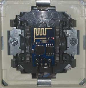
Alteration of the switch did not take much time, threw out the standard LED. He pulled the wires from the module in the center of the switch, the module itself was located outside under the plastic button, and the power part inside. Not a lot of photos of the process (photo from the phone):


nodeMCU
The firmware uses Lua programming language, this language is similar to Javascript. The version is still damp, but the basic functionality is not quite badly implemented. Immediately after loading, the module starts to execute the init.lua script file , in the clean firmware this file does not exist, you have to create it with your hands. All operations can be performed through the console connected to the "com" port, to simplify uploading files to the module there is a luatool script. The fill works as follows, and this code completely shows the process of writing to the file.
file.open("init.lua","w") file.writeline([[print("Hello World!")]]) file.writeline([[--comment]]) file.close() An example of reading the configuration file. It does not look very much. Maybe there is another version of the serialized data.
file.open('config') c_wifi_ssid = string.gsub(file.readline(), "\n", "") c_wifi_key = file.readline() file.close() An example loop using the API with a pause of 1000 milliseconds is presented below:
tmr.alarm(1000, 1, function() if wifi.sta.getip()=="0.0.0.0" then -- ip print("connecting to AP..."..c_wifi_ssid.."/"..c_wifi_key) else print('ip: ',wifi.sta.getip()) tmr.stop() -- alarm stop end end) Work with GPIO
If you have a model of the ESP-01 module of a new revision, then only 2 gpio is available to you, without resorting to a dirty hack.

I decided to refuse such a hack and take advantage of what is.
One gpio button and the second output to the solid-state relay. There is also Tx, but I didn’t work as gpio, and to indicate it, I just send messages to the print () console. So far, that's the way it is. The longer the message, the longer and brighter the LED flashes. The owners of this modification fly through the forest and with features such as (node.key, node.led), because they can only use GPIO16, which is also not divorced on the board.
All gpio can work in several modes (OUTPUT, INPUT, INT), but what is interesting is that the gpio.read () function takes a low level before reading it , even if the OUTPUT mode is set. That is, to get the current exit status, this is not appropriate. I had to use an external variable and write two functions for convenience, and determine the activity through the variable.
function on() gpio.write(8,gpio.LOW) oo=1 end function off() gpio.write(8,gpio.HIGH) oo=0 end The callback gpio.trig (pin, type, function (level)) can be used as an event, the second parameter can take the following values “up”, “down”, “both”, “low”, “high”. Here, it seems, everything is clear. If your output is in state 1 and we drop it to the ground, it is triggered down, then when raised it is triggered up, but, to my regret, this did not happen, in the console I saw only down depending on the speed of pressing the button the event triggered 1 or 2 times. I decided to put a cycle with a pause and breakpoint for 1 on gpio.
for i=1,1000 do print(i) tmr.delay(10) tmr.wdclr() -- end But the pause did not work, and without a pause, the device went into reboot. But print (i) introduced a good delay. Made through tmr.alarm , but currently there can be only one active cycle, which is not very suitable.
function down() tmr.alarm(100, 1, function() timer = timer + 1 -- ok if gpio.read(9) == 1 then print(timer) tmr.stop() if timer < 20 then switch() else -- ... end timer = 0 end tmr.wdclr() end) end gpio.trig(9, "down", function (gp) if timer == 0 then timer = 1 down() end end) HTTP server
The server runs as 2 fingers, but you will not receive any array of request parameters. It is not clear how best: either to write your bike, or find on a substring. Agree, it looks awful. In this example, it looks for 2 parameters key and mode = off, on, party. The last mode is a simple flashing light every 200ms, and you can put it quickly, but I was afraid for the light bulb and the optorele.
function HTTPd() print('start http serv') srv=net.createServer(net.TCP, 5) srv:listen(80,function(conn) conn:on("receive",function(conn,payload) print(payload) if string.find(payload, "key="..c_api_key) then msg = "key_ok" if string.find(payload,"mode=on") then on() else if string.find(payload,"mode=off") then tmr.stop() off() else if string.find(payload, "mode=party") then party(200) end end end else msg = "error_key" end conn:send("<html><head></head><body><h1> mode=[on,off,party] key='api_key' </h1><p>"..msg.."</p></body></html>") end) conn:on("sent",function(conn) conn:close() end) end) end It’s not so difficult to write a simple web interface, and place scripts and styles on external servers. From the module, take only the index page and communicate with it, say, by json, there will not be a big load and everything will fit into the file system, but we become dependent on the availability of the Internet.
Wi-Fi
To connect as a client, this code is enough; ip will be received via DHCP:
wifi.setmode(wifi.STATION) wifi.sta.config(c_wifi_ssid,c_wifi_key) wifi.sta.autoconnect(1) In the third example, you can see how you can determine whether the point is connected or not. I did not use other wifi modes, so there are possible pitfalls.
In general, with a few tricks (crutches), the logic of a simple switch was written. A button can be controlled directly from the console. Putting the program BetterTouchTool , you can use the key combination "curl`it" server switch. Found use button EJECT .
Summary
I do not regret at all that I chose nodeMCU : I did not have to climb into the jungle of the official SDK. It is not necessary to compile the code every time, and the program itself is easy to break into modules and pour into separate pieces. For this it was necessary to pay sometimes with incomprehensible behavior. The main thing is that all the logic is on the switch itself, and when unavailable, wifi will perform its main function, well, only if it burns out. I wish the most rapid development of the nodeMCU project and in the future I will try to do something else, since there is one more module left.
useful links
Source: https://habr.com/ru/post/363827/
All Articles