A little about the basics of LED circuitry
Judging by the comments, many people are interested not only in the parameters of LED lamps, but also in the theory of their internal structure. Therefore, I decided to talk a little about the basics of circuit solutions that are most often used in this area.
')
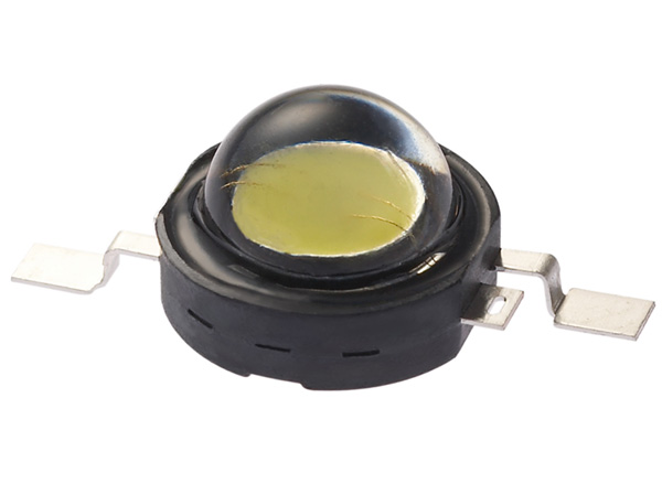
So, the core and the main component of the LED light bulb is the LED. From the point of view of circuit technology, light-emitting diodes are no different from any others, except that in the sense of using them as diodes themselves they have terrible parameters - a very small allowable reverse voltage, a relatively large junction capacity, a huge operating voltage drop (about 3.5 V for white LEDs - for example, for a rectifier diode it would be a nightmare), etc.
However, we understand that the main value of LEDs for humanity is that they glow, and sometimes quite brightly. In order for the LED to glow happily ever after, it needs two conditions: a stable current through it and a good heat sink from it. The quality of the heat sink is provided by various construction methods, because now we will not dwell on this issue. Let's talk about why and how modern humanity achieves the first goal - a stable current.
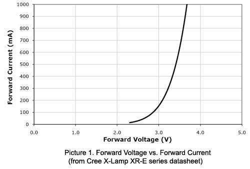
We have already figured out that in the circuit design sense, the LED differs from any other diode only by the values of the parameters. Here we must say that the device is fundamentally nonlinear; that is, to a friend from school, he does not obey Ohm’s law at all. The dependence of the current on the applied voltage on such devices describes the so-called. current-voltage characteristic (VAC), and for the diode it is exponential. It follows from this that the smallest change in the applied voltage leads to a huge change in current, but this is not all — with a change in temperature (as well as aging), the IVC shifts. In addition, the position of the IVC is slightly different for different diodes. I will state separately - not only for each type, but for each copy, even from one party. For this reason, the current distribution through the diodes connected in parallel, will necessarily be uneven, which can not well affect the durability of the structure. In the manufacture of matrices, they try either to use a series connection, which solves the problem at the root, or to choose diodes with approximately the same direct voltage drop. In order to facilitate the task, manufacturers usually indicate the so-called “bin” —a sampling code by parameters (including voltage) into which a specific instance falls.
WAH white LED.
Accordingly, in order for everything to work well, the LED must be connected to a device that, regardless of external factors, will automatically select a voltage with high accuracy at which a given current flows in the circuit (for example, 350 mA for single watt LEDs), and to monitor the process continuously. In general, such a device is called a current source, but in the case of LEDs, it is fashionable today to use the overseas word “driver”. In general, the driver is often referred to as solutions mainly designed to work in a specific application — for example, a “MOSFET driver” —a microchip designed to control specifically powerful field-effect transistors; a seven-segment indicator driver — a solution to control seven-segment specifically, etc. . That is, calling the current source LED driver, people hint that this current source is designed specifically for working with LEDs. For example, it may have specific functions — something in the spirit of having a DMX-512 light interface, detecting an open circuit and a short circuit at the output (and a conventional current source, in general, should work without problems and for a short circuit), etc. However, concepts are often confused, and, for example, the most common adapter (voltage source!) For LED strips is called a driver.
In addition, devices designed to specify the mode of the lighting device, often referred to as ballast.
So, current sources. The simplest source of current can be a resistance connected in series with the LED. So do at low power (somewhere up to half a watt), for example, in the same LED strips. With increasing power, the losses on the resistor become too large, and the requirements for current stability increase, and therefore there is a need for more advanced devices, the poetic image of which I drew above. All of them are built according to the same ideology - they have a regulating element controlled by current feedback.
Current stabilizers are divided into two types - linear and pulsed. Linear circuits are relatives of a resistor (the resistor itself and its analogs also belong to this class). They usually do not give much benefit in efficiency, but they improve the quality of current stabilization. Pulse circuits are the best solution, but they are more complicated and expensive.
Let us now briefly go over what can now be seen inside or near LED lamps.
Condenser ballast is a development of the idea of switching resistance in series with the LED. In principle, the LED can be plugged into the outlet directly like this:
The oncoming diode is necessary in order to prevent the LED from being broken at the moment when the mains voltage changes polarity - I already mentioned that there are no LEDs with a valid reverse voltage of hundreds of volts. In principle, instead of the reverse diode, you can put another LED.
The rating of the resistor in the circuit above is calculated for an LED current of about 10 to 15 mA. Since the mains voltage is much more than the drop on the diodes, the latter can be ignored and read directly according to Ohm's law: 220/20000 ~ 11 mA. You can substitute the peak value (311 V) and make sure that even in the limiting case, the diode current does not exceed 20 mA. Everything goes great, except that the resistor will dissipate about 2.5 W, and about 40 mW on the LED. Thus, the efficiency of the system is about 1.5% (in the case of one LED it will be even less).
The idea of this method is to replace the resistor with a capacitor, because it is known that in AC circuits the reactive elements have the ability to limit the current. By the way, it is also possible to use a choke, moreover, they do it in classical electromagnetic ballasts for fluorescent lamps.
Considering the formula from the textbook , it is easy to obtain that in our case a capacitor with a capacity of 0.2 μF or an inductance of about 60 G is required. Here it becomes clear why chokes are never found in such ballasts of LED lamps - such an inductance coil is a serious and expensive construction, but a 0.2 μF capacitor is much easier to get. Of course, it should be designed for peak mains voltage, and better with a margin. In practice, capacitors with an operating voltage of at least 400 V are used. By slightly adding a circuit, we get what we saw in the previous article.

As I have already said, the advantage of such a ballast is only one thing - simplicity and low cost. Like a ballast with a resistor, not very good current stabilization is provided here, and, even worse, there is a significant reactive component, which is not particularly good for the network (especially at noticeable powers). In addition, as the desired current increases, the required capacitor capacitance will increase. For example, if we want to turn on a one-watt LED operating at a current of 350 mA, we will need a capacitor with a capacity of about 5 microfarads, designed for a voltage of 400 V. This is already more expensive, larger in size and more complex in construction. With the suppression of pulsations here, too, is not easy In general, it can be said that capacitor ballast is forgivable only for small beacon lamps, nothing more.
This circuit solution belongs to the family of transformerless converters, including lowering, enhancing and inverting topology. In addition, the transformerless converters also include SEPIC , Chuka's converter and other exotics, such as switchable capacitors. In principle, the LED driver can be built on the basis of any of them, but in practice they are much less common in this quality (although the increasing topology is used, for example, in many flashlights).
One of the driver variants based on the transformerless step-down topology is shown in the figure below.
In nature, such an inclusion can be observed by the example of ZXLD1474 or the inclusion option of the ZXSC310 (which, by the way, is the boost converter in the initial switching circuit).
Here the LED turns on in series with the coil. The control circuit monitors the current with the help of the measuring resistor R1 and controls the key T1. If the current through the LED falls below a predetermined minimum, the transistor opens, and the coil with the LED connected in series with it turns out to be connected to a power source. The current in the coil starts to grow linearly (the red part of the graph), the diode D1 is locked at this time. As soon as the control circuit registers the achievement of a predetermined maximum current, the key closes. In accordance with the first switching law, the coil tends to maintain the current in the circuit due to the energy stored in the magnetic field. At this moment the current flows through the diode D1. The energy of the coil field is consumed, the current decreases linearly (the green area on the graph). When the current falls below a predetermined minimum, the control circuit registers this and reopens the transistor, pumping energy into the system — the process repeats. Thus, the current is maintained within the specified limits.
A distinctive feature of the lowering topology is the ability to make the pulsations of the luminous flux as small as desired, since in such switching on the current through the LED is never interrupted. The path of approaching the ideal lies through increasing the inductance and increasing the switching frequency (today there are converters with operating frequencies up to several megahertz).
On the basis of this topology, the Gauss lamp driver was considered, which was discussed in the previous article.
The disadvantage of the method is the lack of galvanic isolation - when the transistor is open, the circuit is directly connected to the voltage source, in the case of network LED lamps - to the network, which may be unsafe.
Despite the fact that the flyback converter contains something similar to a transformer, in this case it is more correct to call this part a two-winding choke, since the current never flows through both windings at the same time. In fact, in principle, the flyback converter is similar to transformer topologies. When T1 is open, the current in the primary winding increases, energy is stored in a magnetic field; at the same time, the polarity of switching on the secondary winding is deliberately chosen so that the diode D3 at this stage is closed and the current on the secondary side does not flow. The load current at this moment supports the capacitor C1. When T1 closes, the polarity of the voltage on the secondary winding becomes reversed (since the derivative of the current in the primary winding changes sign), D3 opens and the stored energy is transferred to the secondary side. In the sense of current stabilization, everything is the same - the control circuit analyzes the voltage drop across the resistor R1 and adjusts the time parameters so that the current through the LEDs remains constant. Most often, the flyback converter is used at a power not exceeding 50 W; then it ceases to be expedient due to the increasing losses and the required dimensions of the transformer-choke.
I must say that there are variants of flyback drivers without an optoisolator ( for example ). They rely on the fact that the currents of the primary and secondary windings are connected, and with certain reservations it can be limited to analyzing the current of the primary winding (or, more often, a separate auxiliary winding) - this saves on details and, consequently, reduce the cost of the solution.
The return converter is good in that, firstly, it provides isolation of the secondary section from the network (higher safety), and, secondly, it makes it relatively easy and cheap to produce lamps that are compatible with standard dimmers for incandescent lamps, as well as to arrange factor correction power.
As already mentioned, pulsed sources operate at sufficiently high frequencies (in practice, from 30 kHz, usually around 100 kHz). Therefore, it is clear that a healthy driver by itself cannot be a source of a large ripple coefficient - primarily because at frequencies above 300 Hz this parameter is simply not normalized, and, moreover, high-frequency pulsations are easy enough to filter anyway. The problem is the mains voltage.
The fact is that, of course, all of the above schemes (except for the circuit with the damping capacitor) operate from a constant voltage. Therefore, at the input of any electronic ballast, first of all, there is a rectifier and a storage capacitor. The purpose of the latter is to feed the ballast in those moments when the mains voltage goes below the threshold of the circuit. And here, alas, a compromise is needed - high-voltage electrolytic capacitors of large capacity, firstly, they cost money, and, secondly, they take up precious space in the lamp body. Here the root cause of problems with the power factor. The described circuit with a rectifier has an uneven current consumption. This leads to the emergence of higher harmonics thereof, which is the reason for the deterioration of the parameter of interest to us. Moreover, the better we try to filter the voltage at the input of the ballast, the lower the power factor we get, if not to make some effort. This explains the fact that almost all the low-ripple lamps that we have seen show a very mediocre power factor, and vice versa (of course, the introduction of an active power factor corrector will affect the price, because for now they prefer to save money).
Perhaps this is all that in the first approximation can be said on the subject of electronics LED lamps. I hope that with this article I have to some extent answered all the questions of a circuit design that were given to me in the comments and personal messages.
')
So, the core and the main component of the LED light bulb is the LED. From the point of view of circuit technology, light-emitting diodes are no different from any others, except that in the sense of using them as diodes themselves they have terrible parameters - a very small allowable reverse voltage, a relatively large junction capacity, a huge operating voltage drop (about 3.5 V for white LEDs - for example, for a rectifier diode it would be a nightmare), etc.
However, we understand that the main value of LEDs for humanity is that they glow, and sometimes quite brightly. In order for the LED to glow happily ever after, it needs two conditions: a stable current through it and a good heat sink from it. The quality of the heat sink is provided by various construction methods, because now we will not dwell on this issue. Let's talk about why and how modern humanity achieves the first goal - a stable current.
By the way, about white LEDs
It is clear that white LEDs are most interesting for lighting. They are made on the basis of a crystal emitting blue light, filled with phosphor, re-emitting part of the energy in the yellow-green region. The title picture clearly shows that the current carrying wires go into something yellow - this is the phosphor; the crystal is located under it. On the typical white LED spectrum, a blue peak is clearly visible:
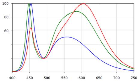
LED spectra with different color temperatures: 5000K (blue), 3700K (green), 2600K (red). Read more here .
LED spectra with different color temperatures: 5000K (blue), 3700K (green), 2600K (red). Read more here .
We have already figured out that in the circuit design sense, the LED differs from any other diode only by the values of the parameters. Here we must say that the device is fundamentally nonlinear; that is, to a friend from school, he does not obey Ohm’s law at all. The dependence of the current on the applied voltage on such devices describes the so-called. current-voltage characteristic (VAC), and for the diode it is exponential. It follows from this that the smallest change in the applied voltage leads to a huge change in current, but this is not all — with a change in temperature (as well as aging), the IVC shifts. In addition, the position of the IVC is slightly different for different diodes. I will state separately - not only for each type, but for each copy, even from one party. For this reason, the current distribution through the diodes connected in parallel, will necessarily be uneven, which can not well affect the durability of the structure. In the manufacture of matrices, they try either to use a series connection, which solves the problem at the root, or to choose diodes with approximately the same direct voltage drop. In order to facilitate the task, manufacturers usually indicate the so-called “bin” —a sampling code by parameters (including voltage) into which a specific instance falls.
WAH white LED.
Accordingly, in order for everything to work well, the LED must be connected to a device that, regardless of external factors, will automatically select a voltage with high accuracy at which a given current flows in the circuit (for example, 350 mA for single watt LEDs), and to monitor the process continuously. In general, such a device is called a current source, but in the case of LEDs, it is fashionable today to use the overseas word “driver”. In general, the driver is often referred to as solutions mainly designed to work in a specific application — for example, a “MOSFET driver” —a microchip designed to control specifically powerful field-effect transistors; a seven-segment indicator driver — a solution to control seven-segment specifically, etc. . That is, calling the current source LED driver, people hint that this current source is designed specifically for working with LEDs. For example, it may have specific functions — something in the spirit of having a DMX-512 light interface, detecting an open circuit and a short circuit at the output (and a conventional current source, in general, should work without problems and for a short circuit), etc. However, concepts are often confused, and, for example, the most common adapter (voltage source!) For LED strips is called a driver.
In addition, devices designed to specify the mode of the lighting device, often referred to as ballast.
So, current sources. The simplest source of current can be a resistance connected in series with the LED. So do at low power (somewhere up to half a watt), for example, in the same LED strips. With increasing power, the losses on the resistor become too large, and the requirements for current stability increase, and therefore there is a need for more advanced devices, the poetic image of which I drew above. All of them are built according to the same ideology - they have a regulating element controlled by current feedback.
Current stabilizers are divided into two types - linear and pulsed. Linear circuits are relatives of a resistor (the resistor itself and its analogs also belong to this class). They usually do not give much benefit in efficiency, but they improve the quality of current stabilization. Pulse circuits are the best solution, but they are more complicated and expensive.
Let us now briefly go over what can now be seen inside or near LED lamps.
1. Condenser ballast
Condenser ballast is a development of the idea of switching resistance in series with the LED. In principle, the LED can be plugged into the outlet directly like this:
The oncoming diode is necessary in order to prevent the LED from being broken at the moment when the mains voltage changes polarity - I already mentioned that there are no LEDs with a valid reverse voltage of hundreds of volts. In principle, instead of the reverse diode, you can put another LED.
The rating of the resistor in the circuit above is calculated for an LED current of about 10 to 15 mA. Since the mains voltage is much more than the drop on the diodes, the latter can be ignored and read directly according to Ohm's law: 220/20000 ~ 11 mA. You can substitute the peak value (311 V) and make sure that even in the limiting case, the diode current does not exceed 20 mA. Everything goes great, except that the resistor will dissipate about 2.5 W, and about 40 mW on the LED. Thus, the efficiency of the system is about 1.5% (in the case of one LED it will be even less).
The idea of this method is to replace the resistor with a capacitor, because it is known that in AC circuits the reactive elements have the ability to limit the current. By the way, it is also possible to use a choke, moreover, they do it in classical electromagnetic ballasts for fluorescent lamps.
Considering the formula from the textbook , it is easy to obtain that in our case a capacitor with a capacity of 0.2 μF or an inductance of about 60 G is required. Here it becomes clear why chokes are never found in such ballasts of LED lamps - such an inductance coil is a serious and expensive construction, but a 0.2 μF capacitor is much easier to get. Of course, it should be designed for peak mains voltage, and better with a margin. In practice, capacitors with an operating voltage of at least 400 V are used. By slightly adding a circuit, we get what we saw in the previous article.
Lyrical digression
"Mikrofarad" will be reduced exactly as the "microfarad". I dwell on this because quite often I see people writing in this context “mF”, while the latter is a contraction from “millifarad,” that is, 1000 uF. In English, "microfarad", again, is not written as "mkF", but, on the contrary, "uF". This is because the letter “u” resembles the letter “μ” with a severed tail.
So, 1 F / F = 1000 mF / mF = 1000000 uF / uF / μF , and nothing else!
In addition, "Farad" - a masculine , as it is named in honor of the great male physicist. So, “four microfarads”, but not “four microfarads”!
So, 1 F / F = 1000 mF / mF = 1000000 uF / uF / μF , and nothing else!
In addition, "Farad" - a masculine , as it is named in honor of the great male physicist. So, “four microfarads”, but not “four microfarads”!
As I have already said, the advantage of such a ballast is only one thing - simplicity and low cost. Like a ballast with a resistor, not very good current stabilization is provided here, and, even worse, there is a significant reactive component, which is not particularly good for the network (especially at noticeable powers). In addition, as the desired current increases, the required capacitor capacitance will increase. For example, if we want to turn on a one-watt LED operating at a current of 350 mA, we will need a capacitor with a capacity of about 5 microfarads, designed for a voltage of 400 V. This is already more expensive, larger in size and more complex in construction. With the suppression of pulsations here, too, is not easy In general, it can be said that capacitor ballast is forgivable only for small beacon lamps, nothing more.
2. Transformerless step-down topology
This circuit solution belongs to the family of transformerless converters, including lowering, enhancing and inverting topology. In addition, the transformerless converters also include SEPIC , Chuka's converter and other exotics, such as switchable capacitors. In principle, the LED driver can be built on the basis of any of them, but in practice they are much less common in this quality (although the increasing topology is used, for example, in many flashlights).
One of the driver variants based on the transformerless step-down topology is shown in the figure below.
In nature, such an inclusion can be observed by the example of ZXLD1474 or the inclusion option of the ZXSC310 (which, by the way, is the boost converter in the initial switching circuit).
Here the LED turns on in series with the coil. The control circuit monitors the current with the help of the measuring resistor R1 and controls the key T1. If the current through the LED falls below a predetermined minimum, the transistor opens, and the coil with the LED connected in series with it turns out to be connected to a power source. The current in the coil starts to grow linearly (the red part of the graph), the diode D1 is locked at this time. As soon as the control circuit registers the achievement of a predetermined maximum current, the key closes. In accordance with the first switching law, the coil tends to maintain the current in the circuit due to the energy stored in the magnetic field. At this moment the current flows through the diode D1. The energy of the coil field is consumed, the current decreases linearly (the green area on the graph). When the current falls below a predetermined minimum, the control circuit registers this and reopens the transistor, pumping energy into the system — the process repeats. Thus, the current is maintained within the specified limits.
A distinctive feature of the lowering topology is the ability to make the pulsations of the luminous flux as small as desired, since in such switching on the current through the LED is never interrupted. The path of approaching the ideal lies through increasing the inductance and increasing the switching frequency (today there are converters with operating frequencies up to several megahertz).
On the basis of this topology, the Gauss lamp driver was considered, which was discussed in the previous article.
The disadvantage of the method is the lack of galvanic isolation - when the transistor is open, the circuit is directly connected to the voltage source, in the case of network LED lamps - to the network, which may be unsafe.
3. The flyback converter
Despite the fact that the flyback converter contains something similar to a transformer, in this case it is more correct to call this part a two-winding choke, since the current never flows through both windings at the same time. In fact, in principle, the flyback converter is similar to transformer topologies. When T1 is open, the current in the primary winding increases, energy is stored in a magnetic field; at the same time, the polarity of switching on the secondary winding is deliberately chosen so that the diode D3 at this stage is closed and the current on the secondary side does not flow. The load current at this moment supports the capacitor C1. When T1 closes, the polarity of the voltage on the secondary winding becomes reversed (since the derivative of the current in the primary winding changes sign), D3 opens and the stored energy is transferred to the secondary side. In the sense of current stabilization, everything is the same - the control circuit analyzes the voltage drop across the resistor R1 and adjusts the time parameters so that the current through the LEDs remains constant. Most often, the flyback converter is used at a power not exceeding 50 W; then it ceases to be expedient due to the increasing losses and the required dimensions of the transformer-choke.
I must say that there are variants of flyback drivers without an optoisolator ( for example ). They rely on the fact that the currents of the primary and secondary windings are connected, and with certain reservations it can be limited to analyzing the current of the primary winding (or, more often, a separate auxiliary winding) - this saves on details and, consequently, reduce the cost of the solution.
The return converter is good in that, firstly, it provides isolation of the secondary section from the network (higher safety), and, secondly, it makes it relatively easy and cheap to produce lamps that are compatible with standard dimmers for incandescent lamps, as well as to arrange factor correction power.
Lyrical digression
The return converter is called so because initially a similar method was used to produce high voltage on televisions based on cathode ray tubes. The high voltage source was circuit-integrated with the horizontal scanning circuit, and a high voltage pulse was produced during the electron beam return .
A little bit of pulsation
As already mentioned, pulsed sources operate at sufficiently high frequencies (in practice, from 30 kHz, usually around 100 kHz). Therefore, it is clear that a healthy driver by itself cannot be a source of a large ripple coefficient - primarily because at frequencies above 300 Hz this parameter is simply not normalized, and, moreover, high-frequency pulsations are easy enough to filter anyway. The problem is the mains voltage.
The fact is that, of course, all of the above schemes (except for the circuit with the damping capacitor) operate from a constant voltage. Therefore, at the input of any electronic ballast, first of all, there is a rectifier and a storage capacitor. The purpose of the latter is to feed the ballast in those moments when the mains voltage goes below the threshold of the circuit. And here, alas, a compromise is needed - high-voltage electrolytic capacitors of large capacity, firstly, they cost money, and, secondly, they take up precious space in the lamp body. Here the root cause of problems with the power factor. The described circuit with a rectifier has an uneven current consumption. This leads to the emergence of higher harmonics thereof, which is the reason for the deterioration of the parameter of interest to us. Moreover, the better we try to filter the voltage at the input of the ballast, the lower the power factor we get, if not to make some effort. This explains the fact that almost all the low-ripple lamps that we have seen show a very mediocre power factor, and vice versa (of course, the introduction of an active power factor corrector will affect the price, because for now they prefer to save money).
Perhaps this is all that in the first approximation can be said on the subject of electronics LED lamps. I hope that with this article I have to some extent answered all the questions of a circuit design that were given to me in the comments and personal messages.
Source: https://habr.com/ru/post/363555/
All Articles