Designing software platform protected NAS

Suppose the NAS hardware is built and the OS is installed on it, for example, as shown here . And now you have a working server with Debian, which is loaded, connected to the network, and you have full physical access to it.
Now you need to design an environment that allows you to easily and safely add, delete application services, and manage their work.
Inspired by an article from a certain Cloud Architect , I decided to make a system in which most services work in containers.
In addition, similar methods (for example, partitioning I / O spaces by container virtualization) are used in fairly important systems of the nuclear industry .
It is very convenient and safe:
- No dependency conflicts. It is possible to keep in the system several different versions of Glibc, php, nginx and everything else, except the kernel.
- No wonder where the scattered configurations.
- Services are easy to stop, start, update, etc ..
- It is easy to add your own settings and changes to each container, no matter where they are, at least in / usr. In the "normal OS" package system will erase such changes and it is necessary to be perverted with hooks so that they are permanent.
- Containers provide a high degree of isolation: one compromised service does not mean full access to all the others and, especially, to the system.
But in his version there is something that I did not like:
- Proxmox is superfluous here. First, for the sake of ZFS support, there is no sense in installing it, since I install the OS with its full support, including root FS, manually. Secondly, it is a NAS, not a virtual machine server, so the Proxmox functionality is redundant. Thirdly, containers and virtual machines can manage OpenMediaVault, and it is inconvenient to have two entry points. Well and, fourthly, the core of Proxmox is supported by OMV , when you connect the OMV Extras repositories, and you do not need to rebuild packages.
- Dependency conflicts are one of the biggest drawbacks that Proxmox brings with OpenMediaVault. Because of this, packages have to be rebuilt, and updating is difficult.
- Installing OMV version 3, when there is a 4th version, in which much has been redone, does not make sense now.
- nginx-proxy-companion for lets-encrypt did not work for me, and I had to solve the certificate problem by another method.
This article offers an option that works on my NAS and so far suits me perfectly.
In order to improve readability, the topic is divided into two articles: design and implementation .
Disk Organization
System SSD
Two SSDs are reserved for the system, and the second SSD is a mirror of the first.
Data structure on SSD:
part_boot- partition with bootloader. Size = 1GB.part_system- the partition with the system. Size = 32 GB (Recommended size: 16 GB * 2).part_slog- a section with SLOG. Size = 5 GB.
SLOG can not be more than the size of RAM = 32 GB + 48 GB swap = 80 GB, 16 GB, taking into account the possible expansion of the swap).
96 GB - absolute limit.
The usual rule for setting the size of a SLOG is to allocate a volume of no more than that which the system can skip in 5 seconds.
In the case of a board with 2 1G interfaces, SLOGsz = 1000/8 2 5 = 1250 MB.
The size with the margin is 5 GB.
part_system and part_slog encrypted in XTS mode.
In general, their organization is:
SSD1: [part_boot] -> [zfs_mirror] <---> SSD2 SSD1: [part_system] -> [crypto_xts] -> [zfs_mirror] <---> SSD2 SSD1: [part_slog] -> [crypto_xts] -> [zfs_zil_mirror] <---> SSD2 Partitions are duplicated using ZFS.
SSD with L2ARC cache
The bottom layer is encrypted using XTS mode on a random key.
Contains two sections:
part_swap- swap partition. Size = 48 GB (max RAM * 1.5 = 32 GB * 1.5).part_l2arc- L2ARC. Size = 196 GB (ARC size * [3..10], ARC size = 0.6 * max RAM size, ie 58 - 196 GB, besides, with deduplication disabled, you need ~ 1 GB L2ARC per 1 TB of data).
swap and l2arc are encrypted with a random key.
A random key for the swap partition is acceptable because the system will not use hibernation.
Under L2ARC, all remaining space is allocated, its real necessity with a memory size of up to 32 GB is questionable.
The size of L2ARC is required to be more precisely adjusted in the process of system operation according to the statistics of cache hits.
Organization:
SSD3: | -> [part_swap] -> [crypto_xts] -> [system swap] | -> [part_l2arc] -> [crypto_xts] -> [l2arc] Disc basket
Since At the first stage it was planned to use 4 disks from 8 possible, all disks in the basket are included in 2 ZFS VDEV.
Each disk first has an XTS encryption layer. A physical ZFS device is organized on top of it.
4 physical devices are combined into one RAIDZ1. If you do not mind the disk space, or more devices (for example, you plan to immediately buy all the disks), it is recommended to make a RAIDZ2 and one array.
- Direct copy to disk in blocks of 4 MB: 185 MB / s (dsync: 136 MB / s)
- LUKS partition with AES-NI command support: 184 MB / s (dsync: 135 MB / s)
- ZFS volume = 170 MB / s (dsync: 50 MB / s).
- LUKS on ZFS volume = 274 MB / s (dsync: 38 MB / s).
- ZFS on LUKS = 187 MB / s (dsync: 50 MB / s)
Hence the conclusion: in spite of the "assurances of experts", it is better to place the ZFS pool over LUKS, and not vice versa. LUKS almost does not contribute overhead (with AES-NI). And it is always possible to enable disk write caching manually (as well as choosing the block size, which is variable in ZFS, too).
The complete scheme is as follows:
HDD1: [crypto_xts] -> [zfs_phdev] | HDD2: [crypto_xts] -> [zfs_phdev] | HDD3: [crypto_xts] -> [zfs_phdev] | -> [RAIDZ1] -> [tank0] HDD4: [crypto_xts] -> [zfs_phdev] | HDD5: [crypto_xts] -> [zfs_phdev] | HDD6: [crypto_xts] -> [zfs_phdev] | HDD7: [crypto_xts] -> [zfs_phdev] | -> [RAIDZ1] -> [tank1] HDD8: [crypto_xts] -> [zfs_phdev] | File System Organization
Pool structure
The NAS will contain various application systems, described below.
Each system adds its own directory to the fixed points of the directory structure of the pool, but the directory names for each system will be described during its design.
Below is the file structure of the pool, common to all systems:
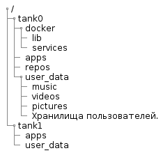
@startsalt { {T +/ ++ tank0 +++ docker ++++ lib ++++ services +++ apps +++ repos +++ user_data ++++ music ++++ videos ++++ pictures ++++ . ++ tank1 +++ apps +++ user_data } } @endsalt In the diagram:
tank0/docker- data of services running in Docker.lib- docker service files. This is a separate file system and is required so that the docker does not clutter/varsnapshots.services- description of containers (for example, dockercompose files) and their service files.
tank0/apps- the repository is the root in which repositories are created for user applications. Within the application subdirectory, the application is free to locate data as it sees fit.tank0/repos- repositories. Here user data will be stored under version control. As I plan to use only Git, the repositories will be contained there directly. But in general, in this directory may be subdirectories for different version control systems.tank0/user_data- the repository is the root in which repositories are created for user data:- books - the user library is stored here.
- music - music users.
- videos - video.
- pictures - various images and photos.
- User repositories (by their names).
tank1/apps- the repository is the root in which repositories are created for user applications. Repeat structure intank0.tank1/user_data- the repository is the root in which repositories are created for user data. Repeat structure intank0.
Storage tank1 allocated for the future: it will be implemented in the case of expanding disk space.
The composition of the system software and the interaction of components
This is what NAS looks like in the context of systems interacting with it:

@startuml ' ----------------------------------------------------- 'left to right direction scale 0.72 package Internet #efefff { cloud "Let's\nEncrypt" as le { } cloud "Cloud DNS" #ffffff { frame "A-" as af { artifact "system.NAS.cloudns.cc" as d1 artifact "omv.NAS.cloudns.cc" as d2 artifact "ldap.NAS.cloudns.cc" as d3 artifact "ssp.NAS.cloudns.cc" as d4 artifact "cloud.NAS.cloudns.cc" as d5 artifact "git.NAS.cloudns.cc" as d6 artifact "backup.NAS.cloudns.cc" as d7 } frame "TXT-" as tf { artifact "Domain:_acme-challenge.*.NAS.cloudns.cc\nTxt value:9ihDbjxxxxxxxxxxxxxxxxxxxxxxxxxxxxxxxxxxxxx" } } cloud " " as ms #ffffff } 'Internet end package LAN #efffef { node as router #ffffff { component "DNS " { artifact ".*\.nas" as ndns } component "NAT" { artifact " 80" as rop80 artifact " 443" as rop443 artifact " 5022" as rop5022 } } node NAS #ffefef { component "" { artifact " 22" as nasp22 artifact " 80" as nasp80 artifact " 443" as nasp443 } package Docker { component "letsencrypt-dns" as led { } component "nginx-reverse-proxy" as nrp { } component "nginx-local" as ngl { } component "LDAP WEB GUI" as ldaps { } component "LDAP SSP" as ssp { } collections " \n(Backup, Cloud, DLNA, etc.)" as services } artifact " " as cert_file component "WEB OMV" as omvwg { } component " OMV" as omv { } component "SSH " as sshd { } component "NUT" as nut { } } } 'LAN end node as ups #ffefef actor as user user <- af user <-> router user <- ms nut <-- ups : USB le <-- af le <-- tf led .-> tf : \n led <-. le : \n led .> cert_file nrp <. cert_file af -> router ndns -> NAS rop80 <--> nasp80 rop443 <--> nasp443 rop5022 <--> nasp22 nasp22 <--> sshd nasp80 <--> nrp nasp443 <--> nrp nrp <--> ngl : \ndocker0 nrp <--> ldaps : \ndocker0 nrp <--> ssp : \ndocker0 ldaps <--> ssp : \ndocker0 nrp <--> services ngl <--> omvwg : omv <--> omvwg : omv .> ms : \n omv ..> sshd : \n WEB GUI omv ..> nut : \n WEB GUI @enduml This cluttered diagram reflects the composition of its services and most of the interactions.
Further components, the appointment of services and operation algorithms will be described in more detail.
operating system
The system, as shown above, is installed on SSDs that are included in the mirror using ZFS. As the OS, OpenMediaVault is selected - the storage management system and WEB GUI (hereinafter - OMV).
It is rather simple to install it with a package, and everything else will be pulled up according to dependencies: the kernel, additional repositories, etc.
System software
The central components are:
- Nginx proxy is a dispatcher with automatic certificate management (using a separate mechanism).
- Docker - containerization system. It provides convenient work with containers: loading images, assembling, configuring, etc ... To manage containers, the OMV plugin is used.
On a physical machine, only OMV, SSH, and demons that the user does not access work. All other systems work inside the Docker containers.
user management
User authentication is done through LDAP. This is done to manage users centrally, and most services support this mechanism, unlike, for example, RADIUS servers and similar, albeit more convenient, new and lightweight solutions.
The LDAP server works in a container, but it can also be accessed from the host network.
Services (gitlab, OMV, cloud, etc.) are configured to use an LDAP server.
Users can change passwords using LDAP Self Service Password .
When adding a user to the system, it is first necessary to register the user using the console or the WEB-interface. I am using PHP LDAP Admin .
If you want to give users rights to operate with the OS, it is possible to use PAM LDAP .
Network
Physical organization
As seen in the deployment diagram, the NAS is located behind a router on the local network. Ideally, in order to increase network security, it would be nice to isolate it in the DMZ using a second router, but this is not necessary.
The user can access the NAS from both the Internet and the local network. Any appeal affects the router.
Since the system has several interfaces, more than one is connected to the router simultaneously (in my case two) and their bonding is organized.
First, the interfaces in this case are not idle.
Secondly, it increases reliability, and in some modes and throughput.
Logical organization
As it is possible to see from the diagram, the router participates in the system operation.
In the case of access from an external network, the router organizes port forwarding. Ports 80 and 443 are used to provide access to services via HTTP and HTTPS, respectively. Port 5022 is forwarded to NAS port 22 for SSH access. Ideally, it is better to have some discipline for assigning port numbers: for example, ports 10001-10999 are assigned to access host services in the NAS, ports 110001-11999 are assigned to access the second home server, etc.
When accessing from the Internet, you need to be able to bind several domain names to your IP. This is implemented in different ways, but I use the option with a cloudy DNS, providing a DNS zone. As such, ClouDNS has been applied.
In the case of access from the local network, the router provides a DNS server. If you move the DNS server from the router to the NAS, the system will be completely autonomous. But it does not make much sense, because Without a functioning router, which serves to organize a local network (including connecting the NAS to the network) and communicating with external networks, it is impossible to use the NAS anyway.
Its DNS server should be able to return a specific IP if the name falls under a regular expression.
For the NAS, there are two entries: " .*\.nas " and " .*\.NAS\.cloudns\.cc ", where the NAS is registered in the ClouDNS zone.
As a result, regardless of whether there is Internet, the router will redirect all calls from the local network to domains in the NAS.cloudns.cc zone on the NAS.
An HTTP request, hitting the port of NAS 80 or 443, is redirected to the port of the container with nginx-reverse-proxy.
It returns a signed certificate to the user for secure access over HTTPS. Then, depending on the domain name, forwards the request to the container with the required service. For example, a request for cloud.NAS.cloudns.cc will be redirected to the container in which the personal cloud is running.
There are two types of services:
- Services running in containers. Their fortend shares the same network as nginx-reverse-proxy. Here the redirection is organized directly.
- Services running on the host. For example, the OMV WEB-interface works directly on the host, not in the container and is not available directly from the external network on port 443 (simply because this port listens to nginx-reverse-proxy).
In the case of services of the second type, the redirection is organized through the nginx-local container containing the domain names of the "iron" host.
The process of passing the request within the NAS is shown in the diagram below. The certificate renewal process shown on the diagram is described below.
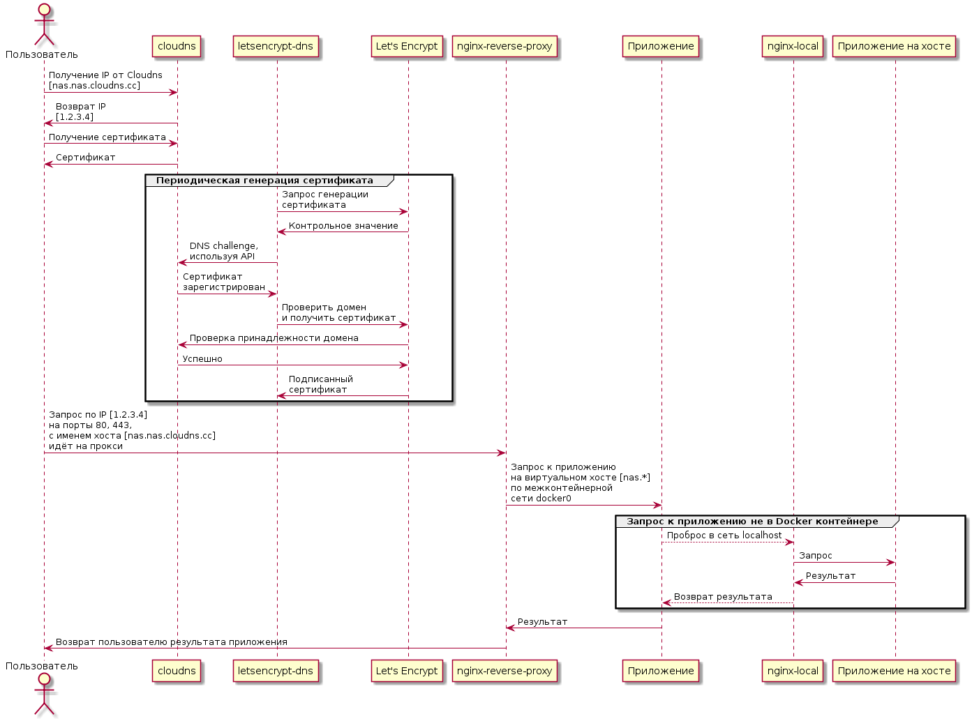
@startuml actor as user participant "cloudns" as cld participant "letsencrypt-dns" as led participant "Let's Encrypt" as le participant "nginx-reverse-proxy" as nrp participant "" as app participant "nginx-local" as ngl user -> cld : IP Cloudns\n[nas.nas.cloudns.cc] user <- cld : IP\n[1.2.3.4] user -> cld : user <- cld : group led -> le : \n led <- le : led -> cld : DNS challenge,\n API led <- cld : \n led -> le : \n cld <- le : cld -> le : led <- le : \nc end user -> nrp : IP [1.2.3.4]\n 80, 443,\n [nas.nas.cloudns.cc]\n nrp -> app : \n [nas.*]\n \n docker0 group Docker app --> ngl : localhost ngl -> " " : ngl <- " " : app <-- ngl : end nrp <- app : user <- nrp : @enduml Certificate
Periodically, a container with letsencrypt-dns receives a certificate for a group of domains. The certificate is obtained using certbot . Before obtaining a certificate, Let's Encrypt service checks whether the domain belongs to the one who requests a certificate for it.
With the case of ClouDNS, this is done using the so-called DNS challenge :
- A random sequence is generated.
- The sequence is inserted into the TXT record.
- Let's Encrypt checks that such a sequence is indeed present.
Insertion into TXT can be done manually or using an API. In order to unify access to different DNS providers, there is a library and a tool Lexicon .
Unfortunately, there is a minus for ClouDNS: its API is paid. Considering that, I did not attach the certificate immediately, and I did not want to redo everything, I just bought access, which costs $ 42 for 2 years (and it would be strange to pinch forty bucks, with a total NAS price of more than $ 3000).
If desired, it is possible to find normal services with a free API.
Network Services
Infrastructure services related to the network that are required for operation and maintenance:
- Nginx-reverse-proxy is a dispatcher that provides data to a service via its URL.
- Lets-encrypt to renew certificates.
- Nginx proxying requests to the host’s network from the container network.
- SSH management is organized using OpenSSH.
- DNS server, as already mentioned, will not be part of the NAS. In order to make the NAS completely autonomous, it certainly does not hurt. But given the fact that NAS is not needed without a network, it is possible to implement it on a router.
- The POP3 / SMTP server shown on the diagram is external and is needed to send alerts from the NAS.
It is possible to use nginx-proxy-companion for obtaining certificates, but it did not work for me.
Interaction with the power source
As the core of the power management system, the NUT daemon was chosen, which is supported by the OMV plugin and which does not have any serious universal alternatives.
Accordingly, the Eaton uninterruptible power supply was initially chosen so that problems in the Linux + NUT bundle did not arise with it.
Eatons, in this case, are generally very well supported . Its only serious drawback is the noise. But it is easily corrected by replacing the fan, which was described in the "iron" article.
In order for the NAS to interact properly and the UPS, you need to configure responses to the events described below.
When the battery reaches its maximum service life, the following is performed:
- Alarm in the WEB interface. The plugin is responsible for this and the requirement is optional.
- Sending a message to e-mail every 24 hours. Also implemented through OMV.
When the power supply is disconnected for more than 1 minute, it is performed:
- Alarm in the WEB interface.
- Sending a message by e-mail.
When the battery drops below the critical level, it is executed:
- Sending a message to e-mail.
- Shut down the system.
Security measures from unauthorized access
Here are just general security measures regarding the NAS:
- All users are logged in: no anonymous access. In the future, it is possible to retreat somewhat from such a scheme. Links to files in the cloud can be provided by third-party users.
- Implemented full disk encryption. Including, the root file system is encrypted.
- Password protection is set on the system settings via EFI.
- System trusted boot. It is an additional tool to control the authenticity of the bootloader.
- Two-factor authentication in the form of a token is possible, but this is not yet implemented.
- Firewall is being used.
- As an additional measure of protection against brute force, it is possible to use fail2ban .
- The introduction of a mandatory access control system will also increase the complexity of remote hacking and may partially offset its consequences.
Reliability Tools
In order to reduce the probability of system failure, are used:
- E-mail alerts (both remote and local) about everything: power off, autopsy, SMART problems.
- SMART monitoring.
- Isolation of applications.
- Additional reservations. For example, replication of data in cloud storage.
If the SMART parameters of any disk reach critical values, the following is performed:
- Alarm in the WEB interface.
- Sending a message to e-mail.
- If possible, drive the disc out of the pool.
System management
Software management is carried out through:
- WEB interface available via HTTPS.
- Ssh. I have a habit of working through the console, and SSH is highly desirable.
- IPMI: system management, with an unloaded OS.
WEB interface
The system provides basic services accessible via HTTPS (in the NAS.cloudns.cc zone from the Internet, or in the nas zone on the local network):
- https: //nas.nas , https: //omv.nas - storage management system interface.
- https: //ssp.nas - interface for changing user password.
- https: //ldap.nas - LDAP server admin interface.
Additional subsystems will add their own interfaces, which are described in the same way.
Organization of application systems
Preliminary composition of systems:
- The system works with the code.
- Backup.
- Cloud storage.
- Download content from the Internet.
- Media system.
Each of the systems will be described separately.
Utility Components
DBMS
Since The DBMS is required for most systems, at the initial stage there was a desire to select one DBMS, based on the capabilities and requirements of the subsystems, and run in a single copy. But in the end, it turned out that using several DBMS, depending on the implementation of the subsystem, is simpler and not particularly costly in terms of resources. On this option, I have stopped.
Additional reservation system
Tasks of this system:
- Duplication of OS configuration and systems. The configuration is backed up to the data pool.
- Saving intermediate states of both the root pool and the data pool.
Composition:
- Plugin OMV backup. .
- zfs-auto-snapshot. , ZFS .
- , , , "" . , , . .
- . , , . , , Microsoft SDL . , .
- , .
- ( 40 ), , . , IPMI, , , NAS , ( IME , IME ).
')
Source: https://habr.com/ru/post/359344/
All Articles